BANDPASS FIR FILTER DESIGN
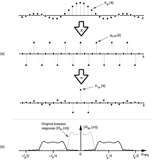
The window method of low-pass FIR filter design can be used as the first step in designing a bandpass FIR filter. Let's say we want a 31-tap FIR filter with the frequency response shown in Figure 5-22(a), but instead of being centered about zero Hz, we want the filter's passband to be centered about fs/4 Hz. If we define a low-pass FIR filter's coefficients as hlp(k), our problem is to find the hbp(k) coefficients of a bandpass FIR filter. As shown in Figure 5-28, we can shift Hlp(m)'s frequency response by multiplying the filter's hlp(k) low-pass coefficients by a sinusoid of fs/4 Hz. That sinusoid is represented by the sshift(k) sequence in Figure 5-28(a), whose values are a sinewave sampled at a rate of four samples per cycle. Our final 31-tap hbp(k) FIR bandpass filter coefficients are

Figure 5-28. Bandpass filter with frequency response centered at fs/4: (a) generating 31-tap filter coefficients hbp(k); (b) frequency magnitude response |Hbp(m)|.

whose frequency magnitude response |Hbp(m)| is shown as the solid curves in Figure 5-28(b). The actual magnitude of |Hbp(m)| is half that of the original |Hlp(m)| because half the values in hbp(k) are zero when sshift(k) corresponds exactly to fs/4. This effect has an important practical implication. It means that, when we design an N-tap bandpass FIR filter centered at a frequency of fs/4 Hz, we only need to perform approximately N/2 multiplications for each filter output sample. (There's no reason to multiply an input sample value, x(n–k), by zero before we sum all the products from Eq. (5-6) and Figure 5-13, right? We just don't bother to perform the unnecessary multiplications at all.) Of course, when the bandpass FIR filter's center frequency is other than fs/4, we're forced to perform the full number of N multiplications for each FIR filter output sample.
Notice, here, that the hlp(k) low-pass coefficients in Figure 5-28(a) have not been multiplied by any window function. In practice, we'd use an hlp(k) that has been windowed prior to implementing Eq. (5-20) to reduce the passband ripple. If we wanted to center the bandpass filter's response at some frequency other than fs/4, we merely need to modify sshift(k) to represent sampled values of a sinusoid whose frequency is equal to the desired bandpass center frequency. That new sshift(k) sequence would then be used in Eq. (5-20) to get the new hbp(k).
URL http://proquest.safaribooksonline.com/0131089897/ch05lev1sec4
 |
Amazon |  |
