IMPROVING IIR FILTERS WITH CASCADED STRUCTURES
Filter designers minimize IIR filter stability and quantization noise problems by building high-performance filters by implementing combinations of cascaded lower performance filters. Before we consider this design idea, let's review important issues regarding the behavior of combinations of multiple filters.
6.8.1 Cascade and Parallel Filter Properties
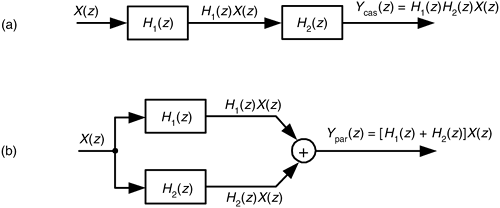
Here we summarize the combined behavior of linear filters (be they IIR or FIR) connected in cascade and in parallel. As indicated in Figure 6-37(a), the resultant transfer function of two cascaded filter transfer functions is the product of those functions, or

Figure 6-37. Combinations of two filters: (a) cascaded filters; (b) parallel filters.

with an overall frequency response of
Equation 6-117

It's also important to know that the resultant impulse response of cascaded filters is the convolution of their individual impulse responses.
As shown in Figure 6-37(b), the combined transfer function of two filters connected in parallel is the sum of their transfer functions, or
Equation 6-118

with an overall frequency response of
Equation 6-119

The resultant impulse response of parallel filters is the sum of their individual impulse responses.
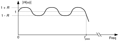
While we are on the subject of cascaded filters, let's develop a rule of thumb for estimating the combined passband ripple of the two cascaded filters in Figure 6-37(a). The cascaded passband ripple is a function of each individual filters' passband ripple. If we represent an arbitrary filter's peak passband ripple on a linear (not dB) vertical axis as shown in Figure 6-38, we can begin our cascaded ripple estimation.
Figure 6-38. Definition of filter passband ripple R.

From Eq. (6-117), the upper bound (the peak) of a cascaded filter's passband response, 1 + Rcas, is the product of the two H1(w) and H2(w) filters' peak passband responses, or
Equation 6-120

For small values of R1 and R2, the R1R2 term becomes negligible, and we state our rule of thumb as
Equation 6-121

Thus, in designs using cascaded filters it's prudent to specify their individual passband ripple values to be roughly half the desired Rcas ripple specification for the final combined filter, or
Equation 6-122

6.8.2 Cascading IIR Filters
Experienced filter designers routinely partition high-order IIR filters into a string of second-order IIR filters arranged in cascade because these lower-order filters are easier to design, are less susceptible to coefficient quantization errors and stability problems, and their implementations allow easier data word scaling to reduce the potential overflow effects of data word size growth.
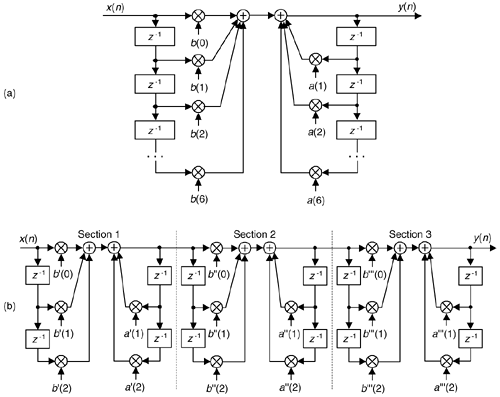
Optimizing the partitioning of a high-order filter into multiple second-order filter sections is a challenging task, however. For example, say we have the sixth-order Direct Form I filter in Figure 6-39(a) that we want to partition into three second-order sections. In factoring the sixth-order filter's H(z) transfer function we could get up to three separate sets of feed forward coefficients in the factored H(z) numerator: b'(k), b''(k), and b'''(k). Likewise we could have up to three separate sets of feedback coefficients in the factored denominator: a'(k), a''(k), and a'''(k). Because there are three second-order sections, there are 3 factorial, or six, ways of pairing the sets of coefficients. Notice in Figure 6-39(b) how the first section uses the a'(k) and b'(k) coefficients, and the second section uses the a''(k) and b''(k) coefficients. We could just as well have interchanged the sets of coefficients so the first second-order section uses the a'(k) and b''(k) coefficients, and the second section uses the a''(k) and b'(k) coefficients. So, there are six different mathematically equivalent ways of combining the sets of coefficients. Add to this the fact that for each different combination of low-order sections there are three factorial distinct ways those three separate 2nd-order sections can be arranged in cascade.
Figure 6-39. IIR filter partitioning: (a) initial sixth-order IIR filter; (b) three second- order sections.

This means if we want to partition a 2M-order IIR filter into M distinct second-order sections, there are M factorial squared, (M!)2, ways to do so. As such, there are then (3!)2 = 36 different cascaded filters we could obtain when going from Figure 6-39(a) to Figure 6-39(b). To further complicate this filter partitioning problem, the errors due to coefficient quantization will, in general, be different for each possible filter combination. Although full details of this subject are outside the scope of this introductory text, ambitious readers can find further material on optimizing cascaded filter sections in References 19, 27, and in Part 3 of Reference 31.
One simple (although perhaps not optimum) method for arranging cascaded second-order sections has been proposed[14]. First, factor a high-order IIR filter's H(z) transfer function into a ratio of the form
Equation 6-123

with the zk zeros in the numerator and pk poles in the denominator. (Hopefully you have a signal processing software package to perform the factorization.) Next, the second-order section assignments go like this:
1. Find the pole, or pole pair, in H(z) closest to the unit circle.
2. Find the zero, or zero pair, closest to the pole, or pole pair, found in step 1.
3. Combine those poles and zeros into a single second-order filter section. This means your first second-order section may be something like:
Equation 6-124

4. Repeat steps 1 to 3 until all poles and zeros have been combined into 2nd-order sections.
5. The final ordering (cascaded sequence) of the sections is based on how far the sections' poles are from the unit circle. Order the sections in either increasing or decreasing pole-distances from the unit circle.
6. Implement your filter as cascaded second-order sections in the order from step 5.
In digital filter vernacular, a second-order IIR filter is called a "biquad" for two reasons. First, the filter's z-domain transfer function includes two quadratic polynomials. Second, the word biquad sounds cool.
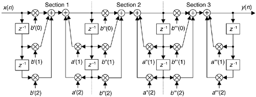
By the way, we started our second-order sectioning discussion with a high-order Direct Form I filter in Figure 6-39(a). We chose that filter form because it's the structure most resistant to coefficient quantization and overflow problems. As seen in Figure 6-39(a), we have redundant delay elements. These can be combined, as shown in Figure 6-40, to reduce our temporary storage requirements, as we did with the Direct Form II structure in Figure 6-22.
Figure 6-40. Cascaded Direct Form I filters with reduced temporary data storage.

There's much material in the literature concerning finite word effects as they relate to digital IIR filters. (References 14, 16, and 19 discuss quantization noise effects in some detail as well as providing extensive bibliographies on the subject.) As for IIR filter scaling to avoid overflow errors, readable design guidance is available[32,33].
URL http://proquest.safaribooksonline.com/0131089897/ch06lev1sec8
 |
Amazon |  |
