WHY CARE ABOUT THE HILBERT TRANSFORM?
The answer is: we need to understand the HT because it's useful in so many complex-signal (quadrature) processing applications. A brief search on the Internet reveals HT-related signal processing techniques being used in the following applications:
- Quadrature modulation and demodulation (communications)
- Automatic gain control (AGC)
- Analysis of two- and three-dimensional complex signals
- Medical imaging, seismic data and ocean wave analysis
- Instantaneous frequency estimation
- Radar/sonar signal processing, and time-domain signal analysis using wavelets
- Time difference of arrival (TDOA) measurements
- High definition television (HDTV) receivers
- Loudspeaker, room acoustics, and mechanical vibration analysis
- Audio and color image compression
- Nonlinear and nonstationary system analysis.
All of these applications employ the HT either to generate or measure complex time-domain signals, and that's where the HT's power lies. The HT delivers to us, literally, another dimension of signal processing capabilities as we move from two-dimensional real signals to three-dimensional complex signals. Here's how.
Let's consider a few mathematical definitions. If we start with a real time-domain signal xr(t), we can associate with it a complex signal xc(t), defined as:

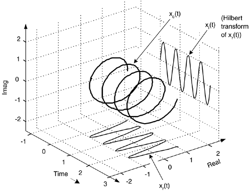
The complex xc(t) signal is known as an analytic signal (because it has no negative-frequency spectral components), and its real part is equal to the original real input signal xr(t). The key here is that xc(t)'s imaginary part, xi(t), is the HT of the original xr(t) as shown in Figure 9-4.
Figure 9-4. Functional relationship between the xc(t) and xr(t) signals.

As we'll see shortly, in many real-world signal processing situations xc(t) is easier, or more meaningful, to work with than the original xr(t). Before we see why that is true, we'll explore xc(t) further to attempt to give it some physical meaning. Consider a real xr(t) = cos(wot) signal that's simply four cycles of a cosine wave and its HT xi(t) sinewave as shown in Figure 9-5. The xc(t) analytic signal is the bold corkscrew function.
Figure 9-5. The Hilbert transform and the analytic signal of cos(wot).

We can describe xc(t) as a complex exponential using one of Euler's equations. That is:
Equation 9-3

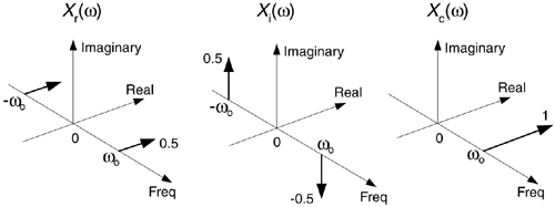
The spectra of those signals in Eq. (9-3) are shown in Figure 9-6. Notice three things in Figure 9-6. First, following the relationships in Eq. (9-3), if we rotate Xi(w) by +90o counterclockwise (+j) and add it to Xr(w), we get Xc(w) = Xr(w)+jXi(w). Second, note how the magnitude of the component in Xc(w) is double the magnitudes in Xr(w). Third, notice how Xc(w) is zero over the negative frequency range. This property of zero spectral content for negative frequencies is why Xc(w) is called an analytic signal. Some people call Xc(w) a one-sided spectrum.
Figure 9-6. HT spectra: (a) spectrum of cos(wot); (b) spectrum of the Hilbert transform of cos(wot), sin(wot); (c) spectrum of the analytic signal of cos(wot),  .
.

To appreciate the physical meaning of our discussion here, let's remember that the xc(t) signal is not just a mathematical abstraction. We can generate xc(t) in our laboratory and route it via cables to the laboratory down the hall. (This idea is described in Section 8.3.)
To illustrate the utility of this analytic signal xc(t) notion, let's see how analytic signals are very useful in measuring instantaneous characteristics of a time domain signal: measuring the magnitude, phase, or frequency of a signal at some given instant in time. This idea of instantaneous measurements doesn't seem so profound when we think of characterizing, say, a pure sinewave. But if we think of a more complicated signal, like a modulated sinewave, instantaneous measurements can be very meaningful. If a real sinewave xr(t) is amplitude modulated so its envelope contains information, from an analytic version of the signal we can measure the instantaneous envelope E(t) value using:
Equation 9-4

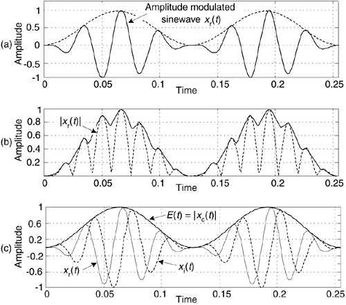
That is, the envelope of the signal is equal to the magnitude of xc(t). We show a simple example of this AM demodulation idea in Figure 9-7(a), where a sinusoidal signal is amplitude modulated by a low-frequency sinusoid (dashed curve). To recover the modulating waveform, traditional AM demodulation would rectify the amplitude modulated sinewave, xr(t), and pass the result through a lowpass filter. The filter's output is represented by the solid curve in Figure 9-7(b) representing the modulating waveform. If, instead, we compute the HT of xr(t) yielding xi(t) and use that to generate the xc(t) = xr(t) + jxi(t) analytic version of xr(t). Finally, we compute the magnitude of xc(t) using Eq. (9-4) to extract the modulating waveform shown as the bold solid curve in Figure 9-7(c). The |xc(t)| function is a much more accurate representation of the modulating waveform than the solid curve in Figure 9-7(b).
Figure 9-7. Envelope detection: (a) input xr(t) signal; (b) traditional lowpass filtering of |xr(t)|; (c) complex envelope detection result |xc(t)|.

Suppose, on the other hand, some real xr(t) sinewave is phase modulated. We can estimate xc(t)'s instantaneous phase ø(t), using:
Equation 9-5

Computing ø(t) is equivalent to phase demodulation of xr(t). Likewise (and more oftentimes implemented), should a real sinewave carrier be frequency modulated we can measure its instantaneous frequency F(t) by calculating the instantaneous time rate of change of xc(t)'s instantaneous phase using:
Equation 9-6

Calculating F(t) is equivalent to frequency demodulation of xr(t). By the way, if ø(t) is measured in radians, then F(t) in Eq. (9-6) is measured in radians/second. Dividing F(t) by 2p will give it dimensions of Hz. (Another frequency demodulation method is discussed in Section 13.22.)
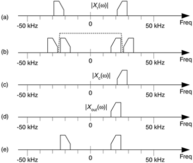
For another HT application, consider a real xr(t) signal whose |Xr(w)| spectral magnitude is centered at 25 kHz as shown in Figure 9-8(a). Suppose we wanted to translate that spectrum to be centered at 20 kHz. We could multiply xr(t) by the real sinusoid cos(2p5000t) to obtain a real signal whose spectrum is shown in Figure 9-8(b). The problem with this approach is we'd need an impractically high-performance filter (the dashed curve) to eliminate those unwanted high-frequency spectral images.
Figure 9-8. Spectra associated with frequency translation of a real signal xr(t).

One the other hand, if we compute the HT of xr(t) to obtain xi(t), combine the two signals to form the analytic signal xc(t) = xr(t)+jxi(t), we'll have the complex xc(t) whose one-sided spectrum is given in Figure 9-8(c). Next we multiply the complex xc(t) by the complex e–j2p5000t, yielding a frequency-translated xout(t) complex signal whose spectrum is shown in Figure 9-8(d). Our final step is to take the real part of xout(t) to obtain a real signal with the desired spectrum centered about 20 kHz, as shown in Figure 9-8(e).
Now that we're convinced of the utility of the HT, let's determine the HT's time-domain impulse response and use it to build Hilbert transformers.
URL http://proquest.safaribooksonline.com/0131089897/ch09lev1sec2
 |
Amazon |  |
