IMPULSE RESPONSE OF A HILBERT TRANSFORMER
Instead of following tradition and just writing down the impulse response equation for a device that performs the HT, we'll show how to arrive at that expression. To determine the HT's impulse response expression, we take the inverse Fourier transform of the HT's frequency response H(w). The garden-variety continuous inverse Fourier transform of an arbitrary frequency function X(f) is defined as:
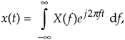
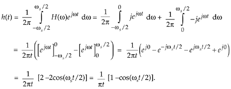
where f is frequency measured in cycles/second (hertz). We'll make three changes to Eq. (9-7). First, in terms of our original frequency variable w = 2pf radians/second, and because df = dw/2p, we substitute dw/2p in for the df term. Second, because we know our discrete frequency response will be periodic with a repetition interval of the sampling frequency ws, we'll evaluate Eq. (9-7) over the frequency limits of –ws/2 to +ws/2. Third, we partition the original integral into two separate integrals. This algebraic massaging gives us the following:
Equation 9-8
Whew! OK, we're going to plot this impulse response shortly, but first we have one hurdle to overcome. Heartache occurs when we plug t = 0 into Eq. (9-8) because we end up with the indeterminate ratio 0/0. Hardcore mathematics to the rescue here. We merely pull out the Marquis de L'Hopital's Rule, take the time derivatives of the numerator and denominator in Eq. (9-8), and then set t = 0 to determine h(0). Following through on this:
Equation 9-9
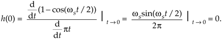
So now we know that h(0) = 0. Let's find the discrete version of Eq. (9-8) because that's the form we can model in software and actually use in our DSP work. We can go digital by substituting the discrete time variable nts in for the continuous time variable t in Eq. (9-8). Using the following definitions
|
n |
= |
discrete time-domain integer index (...,–3,–2,–1,0,1,2,3,...) |
|
fs |
= |
sample rate measured in samples/second |
|
ts |
= |
time between samples, measured in seconds (ts = 1/fs) |
|
ws |
= |
2pfs, |
we can rewrite Eq. (9-8) in discrete form as:
Equation 9-10

Substituting 2pfs for ws, and 1/fs for ts, we have:
Equation 9-11
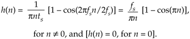
Finally, we plot HT's h(n) impulse response in Figure 9-9. The fs term in Eq. (9-11) is simply a scale factor; its value does not affect the shape of h(n). An informed reader might, at this time, say, "Wait a minute. Eq. (9-11) doesn't look at all like the equation for the HT's impulse response that's in my other DSP textbook. What gives?" The reader would be correct, because one popular expression in the literature for h(n) is:
Equation 9-12

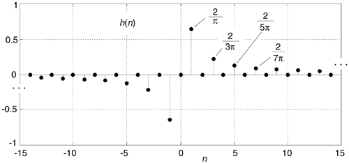
Figure 9-9. The Hilbert transform's discrete impulse response when fs = 1.
Here's the answer; first, the derivation of Eq. (9-12) is based on the assumption that the fs sampling rate is normalized to unity. Next, if you blow the dust off your old mathematical reference book, inside you'll find a trigonometric power relations identity stating: sin2(a) = [1 – cos(2a)]/2. If in Eq. (9-11) we substitute 1 for fs, and substitute 2sin2(pn/2) for [1 – cos(pn)], we see Eqs. (9-11) and (9-12) to be equivalent.
Looking again at Figure 9-9, we can reinforce the validity of our h(n) derivation. Notice that for n > 0 the values of h(n) are non-zero only when n is odd. In addition, the amplitudes of those non-zero values decrease by factors of 1/1, 1/3, 1/5, 1/7, etc. Of what does that remind you? That's right, the Fourier series of a periodic squarewave! This makes sense because our h(n) is the inverse Fourier transform of the squarewave-like H(w) in Figure 9-2. Furthermore, our h(n) is anti-symmetric, and this is consistent with a purely imaginary H(w). (If we were to make h(n) symmetrical by inverting its values for all n < 0, the new sequence would be proportional to the Fourier series of a periodic real squarewave.)
Now that we have the expression for the HT's impulse response h(n), let's use it to build a discrete Hilbert transformer.
URL http://proquest.safaribooksonline.com/0131089897/ch09lev1sec3
| Amazon | ||
