THE Z-TRANSFORM
The z-transform is the discrete-time cousin of the continuous Laplace transform.[ ] While the Laplace transform is used to simplify the analysis of continuous differential equations, the z-transform facilitates the analysis of discrete difference equations. Let's define the z-transform and explore its important characteristics to see how it's used in analyzing IIR digital filters.
[
] In the early 1960s, James Kaiser, after whom the Kaiser window function is named, consolidated the theory of digital filters using a mathematical description known as the z-transform[4,5]. Until that time, the use of the z-transform had generally been restricted to the field of discrete control systems[6–9].
The z-transform of a discrete sequence h(n), expressed as H(z), is defined as

where the variable z is complex. Where Eq. (6-3) allowed us to take the Laplace transform of a continuous signal, the z-transform is performed on a discrete h(n) sequence, converting that sequence into a continuous function H(z) of the continuous complex variable z. Similarly, as the function e–st is the general form for the solution of linear differential equations, z–n is the general form for the solution of linear difference equations. Moreover, as a Laplace function F(s) is a continuous surface above the s-plane, the z-transform function H(z) is a continuous surface above a z-plane. To whet your appetite, we'll now state that, if H(z) represents an IIR filter's z-domain transfer function, evaluating the H(z) surface will give us the filter's frequency magnitude response, and H(z)'s pole and zero locations will determine the stability of the filter.
We can determine the frequency response of an IIR digital filter by expressing z in polar form as z = rejw, where r is a magnitude and w is the angle. In this form, the z-transform equation becomes
Equation 6-17

Equation (6-17) can be interpreted as the Fourier transform of the product of the original sequence h(n) and the exponential sequence r–n. When r equals one, Eq. (6-17) simplifies to the Fourier transform. Thus on the z-plane, the contour of the H(z) surface for those values where |z| = 1 is the Fourier transform of h(n). If h(n) represents a filter impulse response sequence, evaluating the H(z) transfer function for |z| = 1 yields the frequency response of the filter. So where on the z-plane is |z| = 1? It's a circle with a radius of one, centered about the z = 0 point. This circle, so important that it's been given the name unit circle, is shown in Figure 6-13. Recall that the jw frequency axis on the continuous Laplace s-plane was linear and ranged from –  to +
to +  radians/s. The w frequency axis on the complex z-plane, however, spans only the range from –p to +p radians. With this relationship between the jw axis on the Laplace s-plane and the unit circle on the z-plane, we can see that the z-plane frequency axis is equivalent to coiling the s-plane's jw axis about the unit circle on the z-plane as shown in Figure 6-14.
Figure 6-13. Unit circle on the complex z–plane.
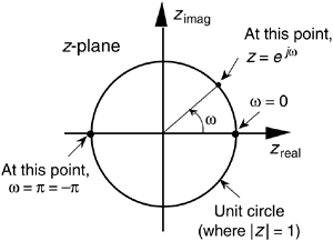
Figure 6-14. Mapping of the Laplace s–plane to the z–plane. All frequency values are in radians/s.
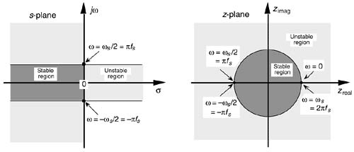
Then, frequency w on the z-plane is not a distance along a straight line, but rather an angle around a circle. With w in Figure 6-13 being a general normalized angle in radians ranging from –p to +p, we can relate w to an equivalent fs sampling rate by defining a new frequency variable ws = 2pfs in radians/s. The periodicity of discrete frequency representations, with a period of ws = 2pfs radians/s or fs Hz, is indicated for the z-plane in Figure 6-14. Where a walk along the jw frequency axis on the s-plane could take us to infinity in either direction, a trip on the w frequency path on the z-plane leads us in circles (on the unit circle). Figure 6-14 shows us that only the –pfs to +pfs radians/s frequency range for w can be accounted for on the z-plane, and this is another example of the universal periodicity of the discrete frequency domain. (Of course the –pfs to +pfs radians/s range corresponds to a cyclic frequency range of –fs/2 to +fs/2.) With the perimeter of the unit circle being z = ejw, later, we'll show exactly how to substitute ejw for z in a filter's H(z) transfer function, giving us the filter's frequency response.
6.3.1 Poles and Zeros on the z–Plane and Stability
One of the most important characteristics of the z-plane is that the region of filter stability is mapped to the inside of the unit circle on the z-plane. Given the H(z) transfer function of a digital filter, we can examine that function's pole locations to determine filter stability. If all poles are located inside the unit circle, the filter will be stable. On the other hand, if any pole is located outside the unit circle, the filter will be unstable. Figure 6-15 shows the z-plane pole locations of several example z-domain transfer functions and their corresponding discrete time-domain impulse responses. It's a good idea for the reader to compare the z-plane and discrete-time responses of Figure 6-15 with the s-plane and the continuous time responses of Figure 6-11. The y(n) outputs in Figures 6-15(d) and (e) show examples of how unstable filter outputs increase in amplitude, as time passes, whenever their x(n) inputs are nonzero. To avoid this situation, any IIR digital filter that we design should have an H(z) transfer function with all of its individual poles inside the unit circle. Like a chain that's only as strong as its weakest link, an IIR filter is only as stable as its least stable pole.
Figure 6-15. Various H(z) pole locations and their discrete time-domain impulse responses: (a) single pole inside the unit circle; (b) conjugate poles located inside the unit circle; (c) conjugate poles located on the unit circle; (d) single pole outside the unit circle; (e) conjugate poles located outside the unit circle.
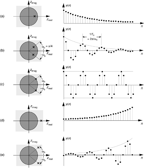
The wo oscillation frequency of the impulse responses in Figures 6-15(c) and (e) is, of course, proportional to the angle of the conjugate pole pairs from the zreal axis, or wo radians/s corresponding to fo = wo/2p Hz. Because the intersection of the –zreal axis and the unit circle, point z = –1, corresponds to p radians (or pfs radians/s = fs/2 Hz), the wo angle of p/4 in Figure 6-15 means that fo = fs/8 and our y(n) will have eight samples per cycle of fo.
6.3.2 Using the z-Transform to Analyze IIR Filters
We have one last concept to consider before we can add the z-transform to our collection of digital signal processing tools. We need to determine what the time delay operation in Figure 6-3 is relative to the z-transform. To do this, assume we have a sequence x(n) whose z-transform is X(z) and a sequence y(n) = x(n–1) whose z-transform is Y(z) as shown in Figure 6-16. The z-transform of y(n) is, by definition,
Equation 6-18

Figure 6-16. Output sequence y(n) equal to a unit delayed version of the input x(n) sequence.

Now if we let k = n–1, then, Y(z) becomes
Equation 6-19

which we can write as
Equation 6-20

Thus, the effect of a single unit of time delay is to multiply the z-transform by z–1.
Interpreting a unit time delay to be equivalent to the z–1 operator leads us to the relationship shown in Figure 6-17, where we can say X(z)z0 = X(z) is the z-transform of x(n), X(z)z–1 is the z-transform of x(n) delayed by one sample, X(z)z–2 is the z-transform of x(n) delayed by two samples, and X(z)z–k is the z-transform of x(n) delayed by k samples. So a transfer function of z–k is equivalent to a delay of kts seconds from the instant when t = 0, where ts is the period between data samples, or one over the sample rate. Specifically, ts = 1/fs. Because a delay of one sample is equivalent to the factor z–1, the unit time delay symbol used in Figures 6-2 and 6-3 is usually indicated by the z–1 operator.
Figure 6-17. Correspondence of the delay operation in the time domain and the z–k operation in the z-domain.

Let's pause for a moment and consider where we stand so far. Our acquaintance with the Laplace transform with its s-plane, the concept of stability based on H(s) pole locations, the introduction of the z-transform with its z-plane poles, and the concept of the z–1 operator signifying a single unit of time delay has led us to our goal: the ability to inspect an IIR filter difference equation or filter structure and immediately write the filter's z-domain transfer function H(z). Accordingly, by evaluating an IIR filter's H(z) transfer function appropriately, we can determine the filter's frequency response and its stability. With those ambitious thoughts in mind, let's develop the z-domain equations we need to analyze IIR filters.
Using the relationships of Figure 6-17, we redraw Figure 6-3 as a general Mth-order IIR filter using the z–1 operator as shown in Figure 6-18. (In hardware, those z–1 operations are shift registers holding successive filter input and output sample values. When implementing an IIR filter in a software routine, the z–1 operation merely indicates sequential memory locations where input and output sequences are stored.) The IIR filter structure in Figure 6-18 is often called the Direct Form I structure.
Figure 6-18. General (Direct Form I) structure of an Mth-order IIR filter, having N feed forward stages and M feedback stages, with the z–1 operator indicating a unit time delay.
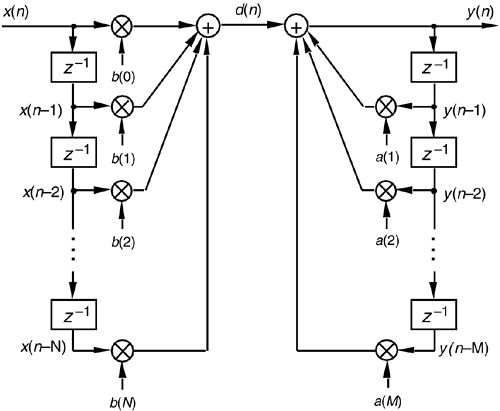
The time-domain difference equation describing the general Mth-order IIR filter, having N feed forward stages and M feedback stages, in Figure 6-18 is
Equation 6-21

In the z-domain, that IIR filter's output can be expressed by
Equation 6-22

where Y(z) and X(z) represent the z-transform of y(n) and x(n). Look Eqs. (6-21) and (6-22) over carefully and see how the unit time delays translate to negative powers of z in the z-domain expression. A more compact form for Y(z) is
Equation 6-23

OK, now we've arrived at the point where we can describe the transfer function of a general IIR filter. Rearranging Eq. (6-23) to collect like terms,
Equation 6-24

Finally, we define the filter's z-domain transfer function as H(z) = Y(z)/X(z), where H(z) is given by
Equation 6-25

(Just like Laplace transfer functions, the order of our z-domain transfer function is defined by the largest exponential order of z in the denominator, in this case M.) Equation (6-25) tells us all we need to know about an IIR filter. We can evaluate the denominator of Eq. (6-25) to determine the positions of the filter's poles on the z-plane indicating the filter's stability.
Remember, now, just as the Laplace transfer function H(s) in Eq. (6-9) was a complex-valued surface on the s-plane, H(z) is a complex-valued surface above, or below, the z-plane. The intersection of that H(z) surface and the perimeter of a cylinder representing the z = ejw unit circle is the filter's complex frequency response. This means that substituting ejw for z in Eq. (6-25)'s transfer function gives us the expression for the filter's HIIR(w) frequency response as
Equation 6-26

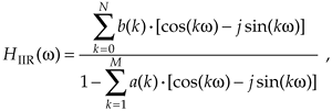
Let's alter the form of Eq. (6-26) to obtain more useful expressions for HIIR(w)'s frequency magnitude and phase responses. Because a typical IIR filter frequency response HIIR(w) is the ratio of two complex functions, we can express HIIR(w) in its equivalent rectangular form as
Equation 6-27
or
Equation 6-28

It's usually easier and, certainly, more useful, to consider the complex frequency response expression in terms of its magnitude and phase. Let's do this by representing the numerator and denominator in Eq. (6-28) as two complex functions of radian frequency w. Calling the numerator of Eq. (6-28) Num(w), then,
Equation 6-29

where

and
Equation 6-30

Likewise, the denominator in Eq. (6-28) can be expressed as
Equation 6-31

where

and
Equation 6-32

These Num(w) and Den(w) definitions allow us to represent HIIR(w) in the more simple forms of
Equation 6-33

Equation 6-33'

Given the form in Eq. (6-33) and the rules for dividing one complex number by another, provided by Eqs. (A-2) and (A-19') in Appendix A, the frequency magnitude response of a general IIR filter is
Equation 6-34

Furthermore, the filter's phase response øIIR(w) is the phase of the numerator minus the phase of the denominator, or
Equation 6-35

To reiterate our intent here, we've gone through the above algebraic gymnastics to develop expressions for an IIR filter's frequency magnitude response |HIIR(w)| and phase response øIIR(w) in terms of the filter coefficients in Eqs. (6-30) and (6-32). Shortly, we'll use these expressions to analyze an actual IIR filter.
Pausing a moment to gather our thoughts, we realize that we can use Eqs. (6-34) and (6-35) to compute the magnitude and phase response of IIR filters as a function of the frequency w. And again, just what is w? It's the normalized radian frequency represented by the angle around the unit circle in Figure 6-13, having a range of –p  w
w  + p. In terms of a discrete sampling frequency ws measured in radians/s, from Figure 6-14, we see that w covers the range –ws/2
  w
w  +ws/2. In terms of our old friend fs Hz, Eqs. (6-34) and (6-35) apply over the equivalent frequency range of –fs/2 to +fs/2 Hz. So, for example, if digital data is arriving at the filter's input at a rate of fs = 1000 samples/s, we could use Eq. (6-34) to plot the filter's frequency magnitude response over the frequency range of –500 Hz to +500 Hz.
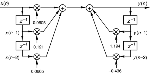
Although the equations describing the transfer function HIIR(w), its magnitude response |HIIR(w)|, and phase response øIIR(w) look somewhat complicated at first glance, let's illustrate their simplicity and utility by analyzing the simple second-order low-pass IIR filter in Figure 6-19 whose positive cutoff frequency is ws/10. By inspection, we can write the filter's time-domain difference equation as
Equation 6-36

Figure 6-19. Second-order low-pass IIR filter example.
or the z-domain expression as
Equation 6-37

Using Eq. (6-25), we write the z-domain transfer function H(z) as
Equation 6-38

Replacing z with ejw, we see that the frequency response of our example IIR filter is
Equation 6-39

We're almost there. Remembering Euler's equations and that cos(0) = 1 and sin(0) = 0, we can write the rectangular form of HIIR(w) as
Equation 6-40

Equation (6-40) is what we're after here, and if we calculate its magnitude over the frequency range of –p  w
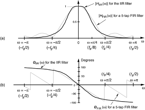
w  p, we get the |HIIR(w)| shown as the solid curve in Figure 6-20(a). For comparison purposes we also show a 5-tap low-pass FIR filter magnitude response in Figure 6-20(a). Although both filters require the same computational workload, five multiplications per filter output sample, the low-pass IIR filter has the superior frequency magnitude response. Notice the steeper roll-off and lower sidelobes of the IIR filter relative to the FIR filter.[
 ]
]
[
] To make this IIR and FIR filter comparison valid, the coefficients used for both filters were chosen so that each filter would approximate the ideal low-pass frequency response shown in Figure 5-17(a).
Figure 6-20. Frequency responses of the example IIR filter (solid line) in Figure 6-19 and a 5-tap FIR filter (dashed line): (a) magnitude responses; (b) phase responses.
A word of warning here. It's easy to reverse some of the signs for the terms in the denominator of Eq. (6-40), so be careful if you attempt these calculations at home. Some authors avoid this problem by showing the a(k) coefficients in Figure 6-18 as negative values, so that the summation in the denominator of Eq. (6-25) is always positive. Moreover, some commercial software IIR design routines provide a(k) coefficients whose signs must be reversed before they can be applied to the IIR structure in Figure 6-18. (If, while using software routines to design or analyze IIR filters, your results are very strange or unexpected, the first thing to do is reverse the signs of the a(k) coefficients and see if that doesn't solve the problem.)
The solid curve in Figure 6-20(b) is our IIR filter's øIIR(w) phase response. Notice its nonlinearity relative to the FIR filter's phase response. (Remember now, we're only interested in the filter phase responses over the low-pass filters' passband. So those phase discontinuities for the FIR filter are of no consequence.) Phase nonlinearity is inherent in IIR filters and, based on the ill effects of nonlinear phase introduced in the group delay discussion of Section 5.8, we must carefully consider its implications whenever we decide to use an IIR filter instead of an FIR filter in any given application. The question any filter designer must ask and answer, is "How much phase distortion can I tolerate to realize the benefits of the reduced computational load and high data rates afforded by IIR filters?"
To determine our IIR filter's stability, we must find the roots of the Eq. (6-38) H(z)'s denominator second-order polynomial. Those roots are the poles of H(z) if their magnitudes are less than one, the filter will be stable. To determine the two poles zp1 and zp2, first we multiply H(z) by z2/z2 to obtain polynomials with positive exponents. After doing so, H(z)'s denominator is
Equation 6-41

Factoring Eq. (6-41) using the quadratic equation from Eq. (6-15), we obtain the factors
Equation 6-42

So when z = –zp1 = 0.597 –j0.282 or z = –zp2 = 0.597 +j0.282, the filter's H(z) transfer function's denominator is zero and H(z) is infinite. We show the 0.597 +j0.282 and 0.597 –j0.282 pole locations, along with a crude depiction of the |H(z)| surface, in Figure 6-21(a). Because those pole locations are inside the unit circle (their magnitudes are less than one), our example IIR filter is stable.
Figure 6-21. IIR filter z-domain: (a) pole locations; (b) frequency magnitude response.
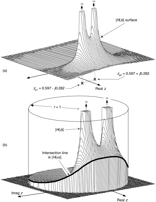
While we're considering at the |H(z)| surface, we can show its intersection with the unit circle as the bold curve in Figure 6-21(b). Because z = rejw, with r restricted to unity then z = ejw and the bold curve is |H(z)||z|=1 = |H(w)|, representing the lowpass filter's frequency magnitude response on the z-plane. The |H(w)| curve corresponds to the |HIIR(w)| in Figure 6-20(a).
6.3.3 Alternate IIR Filter Structures
The Direct Form I structure of the IIR filter in Figure 6-18 can be converted to alternate forms. It's easy to explore this idea by assuming that there is an equal number of feed forward and feedback stages, letting M = N = 2 as in Figure 6-22(a), and thinking of the feed forward and feedback stages as two separate filters. Because both halves of the filter are linear we can swap them, as shown in Figure 6-22(b), with no change in the final y(n) output.
Figure 6-22. Rearranged 2nd-order IIR filter structures: (a) Direct Form I; (b) modified Direct Form I; (c) Direct Form II; (d) transposed Direct Form II.
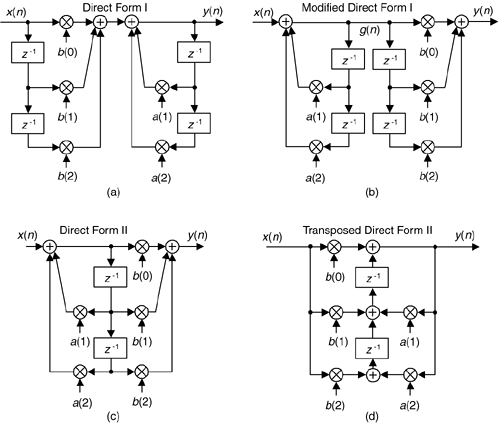
The two identical delay paths in Figure 6-22(b) provide the motivation for this reorientation. Because the sequence g(n) is being shifted down along both delay paths in Figure 6-22(b), we can eliminate one of the paths and arrive at the simplified Direct Form II filter structure shown in Figure 6-22(c), where only half the delay storage registers are required compared to the Direct Form I structure.
Another popular IIR structure is the transposed form of the Direct Form II filter. We obtain a transposed form by starting with the Direct Form II filter, convert its signal nodes to adders, convert its adders to signal nodes, reverse the direction of its arrows, and swap x(n) and y(n). (The transposition steps can also be applied to FIR filters.) Following these steps yields the transposed Direct Form II structure given in Figure 6-22(d).
The filters in Figure 6-22 all have the same performance just so long as infinite precision arithmetic is used. However; using quantized filter coefficients, and with truncation or rounding being used to combat binary overflow errors, the various filters exhibit different noise and stability characteristics. In fact, the transposed Direct Form II structure was developed because it has improved behavior over the Direct Form II structure when integer arithmetic is used. Common consensus among IIR filter designers is that the Direct Form I filter has the most resistance to coefficient quantization and stability problems. We'll revisit these finite-precision arithmetic issues in Section 6.7.
By the way, because of the feedback nature of IIR filters, they're often referred to as recursive filters. Similarly, FIR filters are often called nonrecursive filters. A common misconception is that all recursive filters are IIR. This not true, FIR filters can be designed with recursive structures. (See Section 7.1) So, recursive and nonrecursive should be applied to a filter's structure, and the IIR and FIR should be used to describe the duration of the filter's impulse response[10,11].
Now that we have a feeling for the performance and implementation structures of IIR filters, let's briefly introduce three filter design techniques. These IIR design methods go by the impressive names of impulse invariance, bilinear transform, and optimized methods. The first two methods use analytical (pencil and paper algebra) filter design techniques to approximate continuous analog filters.[ ] Because analog filter design methods are very well understood, designers can take advantage of an abundant variety of analog filter design techniques to design, say, a digital IIR Butterworth filter with its very flat passband response, or perhaps go with a Chebyshev filter with its fluctuating passband response and sharper passband-to-stopband cutoff characteristics. The optimized methods (by far the most popular way of designing IIR filters) comprise linear algebra algorithms available in commercial filter design software packages.
[
] Due to its popularity, throughout the rest of this chapter we'll use the phrase analog filter to designate those hardware filters made up of resistors, capacitors, and (maybe) operational amplifiers.
The impulse invariance, bilinear transform design methods are somewhat involved, so a true DSP beginner is justified in skipping those subjects upon first reading this book. However, those filter design topics may well be valuable sometime in your future as your DSP knowledge, experience, and challenges grow.
URL http://proquest.safaribooksonline.com/0131089897/ch06lev1sec3
 |
Amazon |  |
