Creating Scaled Office Spaces
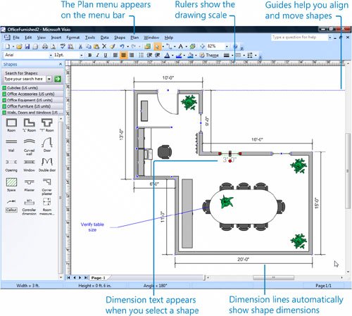
The Office Layout template makes it easy to create scaled office space diagrams with architectural details, such as pilasters (rectangular wall projections like columns) and door swing (the space needed to open or close a door). Because Visio creates diagrams with architectural and engineering precision, your scaled diagrams are as accurate as your measurements.
All Visio templates have a default drawing scale, but for most business diagrams, such as flowcharts or organization charts, that scale is 1:1that is, no scale. In the Office Layout template, the default drawing scale is ½ inch to 1 foot, which means that a shape that is ½ inch wide on the drawing page represents an object that is 1 foot wide in the real world. Visio sets up the drawing page using the template's scale and units of measure, which are typically inches (although Visio includes metric templates as well). If you prefer to measure shapes in yards or meters or some other measurement unit, you can click the Page Setup command on the File menu, which is also how you change the drawing scale for a diagram. In addition, the Office Layout template adds the custom Plan menu, which includes commands specifically for working with floor plans.
When you start a diagram with a scaled template, the units of measure for the drawing scale appear on the rulers. Part of what you have to do when working in any scaled diagram is grow accustomed to measuring distance in real-world units. For example, if your drawing scale is ½ inch to 1 foot on letter-sized paper (11 by 8½ inches), the rulers show that the page represents a space that is 22 feet long and 17 feet wide.
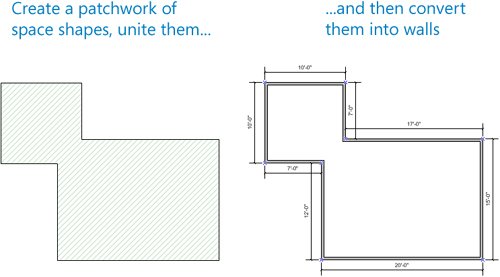
You start an office layout by adding shapes that represent the structure of the office space. One way to do this is to drag wall shapes onto the drawing page and rotate them into position. Where two walls meet, Visio joins their corners for a smooth look. All the other structural shapes, such as doors and windows, are designed to snap to the wall shapes in an office layout. Alternatively, you can use the Space shape, which represents a 10-foot by 10-foot area, to create the office structure. For this technique, you first create a patchwork of space shapes, and then you unite them into a single area by using the Union command, which merges the shapes to create a new shapethat is, one that represents the entire office space. Last, you convert the new shape (the office space) into walls. This sounds time consuming, but most people find it faster and easier than dragging a lot of individual wall shapesone at a timeonto the drawing page.
When you need to measure areas precisely, Visio offers several helpful shortcuts. Some shapes display their own dimensionsfor example, the Space shape displays 100 sq. ft. The status bar below the drawing page shows the real-world units of measure, so you can see at a glance how large shapes are in the real world. Guidesvisual reference lineshelp you align shapes to an exact point as well. Shapes connect to guides to ensure perfect alignment, and you can even drag a guide to move all the shapes connected to it. As you move or resize walls, the shape's dimensions and its dimension text and lines are updated automatically. To show the dimension text for a shape, select the shape. To add a dimension line to a shape, use the Controller dimension shape on the Walls, Doors and Windows stencil.
In this exercise, you start a new office layout with the Office Layout template and use the Page Setup command to change the drawing scale. You use Space shapes to build a scaled office space, unite the shapes to create a new space shape, and then convert the space shape to walls. Then you resize some of the shapes, add dimension lines to them, and connect them to guides that help you position them.
Tip
If you have Visio Professional 2007, you can insert AutoCAD drawings into your Visio architectural diagrams or start a diagram with a building shell already created in a CAD (computer-aided design) program. For more information about inserting and using AutoCAD drawings, type AutoCAD in the Type A Question For Help box.
|
1. |
Start Visio. In the Template Categories list, click Maps and Floor Plans. Under All Templates, double-click Office Layout. |
|
2. |
On the File menu, click Page Setup to open the Page Setup dialog box. |
|
3. |
Click the Drawing Scale tab. 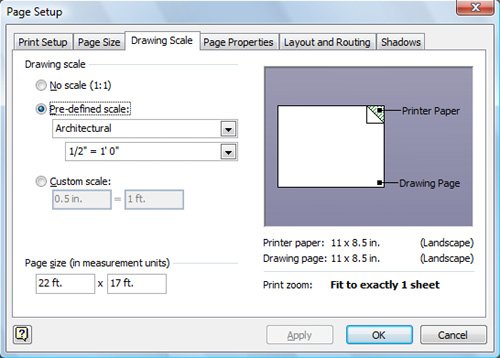
|
|
4. |
In the Pre-defined scale area, click the down arrow on the second box, scroll up, and then click ¼" = 1'0". 
|
|
5. |
Click OK. |
|
6. |
From the Walls, Doors and Windows stencil, drag a Space shape onto the drawing page and position it so that its top edge is at the 24-foot mark shown on the vertical ruler and its left edge is at the 10-foot mark shown on the horizontal ruler. 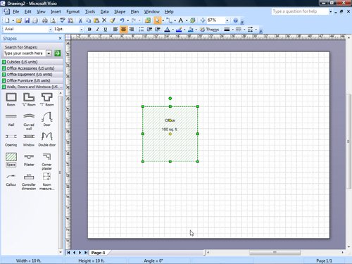
Tip As you drag a shape, Visio displays dotted lines on the rulers and measurements in the status bar that show you the shape's exact position on the drawing page. |
|
7. |
Drag a second Space shape onto the drawing page and position it so that its upper-left corner overlaps the lower-right corner of the first Space shape. 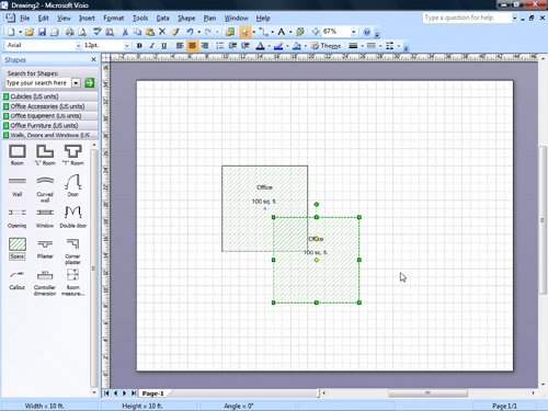
|
|
8. |
On the selected Space shape, drag the right-middle selection handle to the right to increase the width of the shape to 20 feet. Use the Width field in the status bar at the bottom of the drawing page window to determine the shape's width. |
|
9. |
On the same shape, drag the lower-middle selection handle down to increase the height of the shape to 15 feet. Use the Height field in the status bar at the bottom of the drawing page window to determine the shape's height. 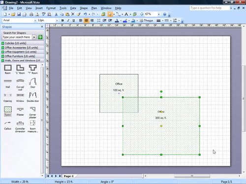
|
|
10. |
Hold down the |
|
11. |
On the Shape menu, point to Operations, and then click Union. 
|
|
12. |
With the shape selected, on the Plan menu, click Convert to Walls.
Tip Another way to create walls is to use the Line or Rectangle tool to draw a rough approximation of the walls, and then use the Convert To Walls command. |
|
13. |
In the Settings area, select the Add dimensions check box, and then click OK. 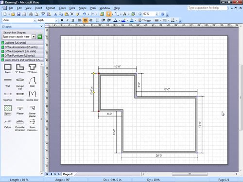
|
|
14. |
Select the top 10-foot wall. |
|
15. |
Right-click the same 10-foot wall, and then click Add a Guide on the shortcut menu. 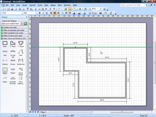
|
|
16. |
Pause the pointer over the guide, and when a two-headed arrow appears, drag the guide up 3 feet to the 27-foot mark on the vertical ruler. Two-headed arrow
|
|
17. |
Press the Tip To select a guide, click it just as you would any shape. To add a guide to the drawing page, position the pointer over the horizontal ruler for a horizontal guide or the vertical ruler for a vertical guide, and then drag. As you drag, the guide appears on the drawing page. To delete a guide from the drawing page, select it, and then press the |
|
18. |
On the Standard toolbar, click the Save button to open the Save As dialog box. Save
|
|
19. |
In the File name box, type NewOffice, and then click Save to save the diagram. |
 key while you select the other Space shape so that both shapes are selected.

 key to deselect the guide.
 key.
key.
CLOSE the NewOffice file.
Tip
Although office layouts are a common type of scaled diagram, you can define a scale for any drawing type in Visio. For example, you can create maps, parts diagrams, and physical network diagrams to scale by using the Page Setup command on the File menu to define a drawing scale.
Quick Reference
Getting Started with Visio 2007
- Getting Started with Visio 2007
- Starting Diagrams by Using Templates
- Working Within the Visio Environment
- Customizing the Visio Environment
- Getting Visio and Diagram Help
- Key Points
Adding Shapes to Diagrams
- Adding Shapes to Diagrams
- Working with 1-D and 2-D Shapes
- Adding Text to Shapes and the Drawing Page
- Moving, Sizing, Rotating, and Copying Shapes
- Working with Groups
- Finding Shapes for Diagrams
- Inserting Pictures into Diagrams
- Key Points
Formatting Shapes and Diagrams
- Formatting Shapes and Diagrams
- Formatting Individual Shapes
- Adding Decorative Elements to Diagrams
- Applying Themes to Entire Diagrams
- Key Points
Connecting Shapes
- Connecting Shapes
- Connecting Shapes in Flowcharts
- Modifying Shape Connections
- Changing the Layout of Connected Shapes
- Key Points
Creating Project Schedules
- Creating Project Schedules
- Creating Timelines to View Projects at a Glance
- Exporting Timelines to Create Gantt Charts
- Tracking Project Details with Gantt Charts
- Key Points
Creating Organization Charts
- Creating Organization Charts
- Importing Data to Create Organization Charts
- Storing and Displaying Employee Information in Organization Charts
- Customizing the Layout of Organization Charts
- Key Points
Laying Out Office Spaces
- Laying Out Office Spaces
- Creating Scaled Office Spaces
- Adding Door, Window, and Furniture Shapes to Office Layouts
- Organizing Shapes in Office Layouts by Using Layers
- Key Points
Creating Network Diagrams
- Creating Network Diagrams
- Connecting Shapes in Network Diagrams
- Storing Information with Network Shapes
- Creating Network Reports
- Key Points
Glossary
About the Authors
Choose the Right Book for You
EAN: 2147483647
Pages: 81
