Modifying Shape Connections
Not only does Visio make it easy to create connections in diagrams, it also makes it easy to modify those connections. Perhaps you need to add a missing step to a flowchart or adjust a series of steps to make a process more efficient. Maybe you need some of the connectors in a flowchart to be rerouted in a specific way. With Visio, you can insert shapes between shapes that are already connected and move shapes around while the connections stay intact, which makes modifying a flowchart painless.
In the previous exercise, you connected shapes with a shape-to-shape connection; that is, you connected shapes without specifying a point of connection. When you move shapes connected by a shape-to-shape connection, the connector reroutes and connects the shapes between the two closest points on the shapes. When you insert a shape between two shapes that are connected by a shape-to-shape connection, Visio connects all three shapes. For most types of flowcharts, shape-to-shape connections are sufficient because you don't usually need to control the exact point of connection on each shape. When you select the connector between two shapes with a shape-to-shape connection, the glued connector endpoints are large, light red, and have no begin point or end point symbols.

There might be times when you're working within design constraints that, for example, require all Yes connectors to flow from the right side of the shapes and all No connectors to flow downward in a flowchart. When you need total control over your shape connections, you can connect shapes with a point-to-point connection, which connects specific points on the shapes. When you move shapes connected by a point-to-point connection, the connector stays connected to those specific points, regardless of where you move the shapes. When you add a shape between two shapes already connected by a point-to-point connection, Visio connects all three shapes at specific connection points. When you select the connector between shapes connected by a point-to-point connection, the glued endpoints on the connector are small, dark red, and include begin and end point symbols.
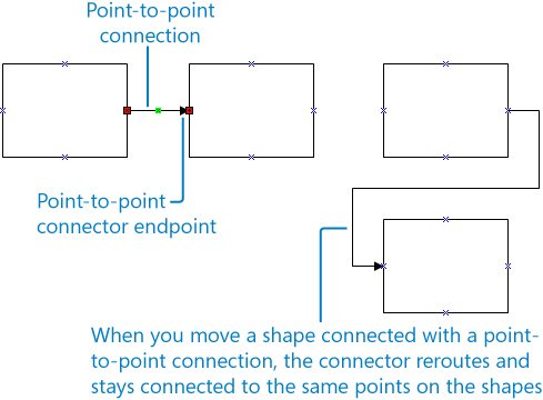
To create a point-to-point connection, instead of positioning the Connector tool over the shape, you position it over a connection pointa specific point, represented by a blue x symbol.
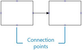
When you place the Connector tool over a connection point on a shape, a small red box appears. Then you drag the connector to the small red box around the connection point on the shape to which you are connecting.
Tip
You can use both shape-to-shape connections and point-to-point connections in a flowchart. You can also create your own connection points. For information about creating connection points and the different types of connection points, type connection points in the Type A Question For Help box.
In this exercise, you move a flowchart shape to a new position and see how the connector moves with the shape. You also insert a flowchart shape between two shapes that are already connected. Then you create a point-to-point connection between a couple of shapes using the Connector tool. Finally, you modify a connector segment and attach a connector endpoint to a different shape.
OPEN the ConnectModify file in DocumentsMicrosoft PressVisio 2007 SBS�4_Connect.
|
1. |
Drag the Send Denial shape down approximately one inch. 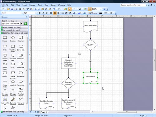
Tip You might need to zoom in to see the shapes better. Also, you can use the dynamic grid to precisely position the shape or hold down the |
|
2. |
From the Basic Flowchart Shapes stencil, drag a Process shape onto the drawing page and position it on the connector between the Qualify? shape and the Send Denial shape. Scissors icon
|
|
3. |
Release the mouse button. 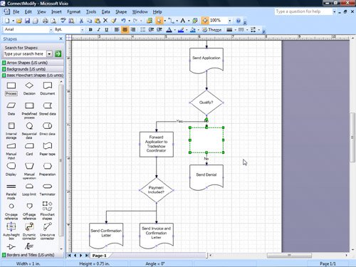
Important Not all templates and connectors support connector-splitting behavior. To determine whether a template and connector support this behavior, drag a shape onto a connector between two shapes. If the connector is rerouted around the shape rather than attaching to it, the template, connector, or both don't support this behavior. To determine whether a particular connector supports splitting behavior, right-click the connector, point to Format on the shortcut menu, and then click Behavior to see the Connector splitting settings. |
|
4. |
With the Process shape selected, type Forward to Tradeshow Assistant. |
|
5. |
Click the connector between the Forward to Tradeshow Assistant shape and the Send Denial shape. |
|
6. |
Press the Tip To delete a connector, select it, and then press the |
|
7. |
Click the pasteboard to deselect the shape. |
|
8. |
Select the connector between the Payment Included? shape and the Send Invoice and Confirmation Letter shape. 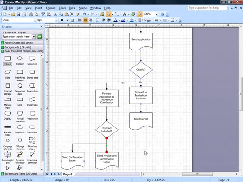
|
|
9. |
Drag the Send Confirmation Letter shape to the left a little, and use the dynamic grid to align the shape with the Send Invoice and Confirmation Letter shape. 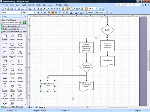
|
|
10. |
Select some of the other connectors in the flowchartone by oneand notice that all the shapes in the flowchart are connected with shape-to-shape connections. |
|
11. |
From the Basic Flowchart Shapes stencil, drag a Process shape onto the drawing page and position it below the Send Confirmation Letter shape. |
|
12. |
With the Process shape selected, type Phone Exhibitor about Payment. |
|
13. |
Click the pasteboard to deselect the shape. |
|
14. |
On the Standard toolbar, click the Connector Tool button. Connector Tool
|
|
15. |
Position the pointer over the bottom connection point on the Send Confirmation Letter shape. 
|
|
16. |
Drag the pointer to the top connection point on the Phone Exhibitor about Payment shape. 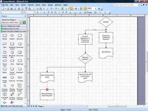
|
|
17. |
Release the mouse button. 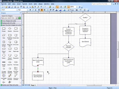
|
|
18. |
Click the Phone Exhibitor about Payment shape to select it. |
|
19. |
From the Basic Flowchart Shapes stencil, drag a Process shape onto the drawing page and position it below the Phone Exhibitor about Payment shape. |
|
20. |
With the Process shape selected, type Payment Received, and then press the |
|
21. |
Position the pointer over the right connection point on the Payment Received shape. |
|
22. |
Drag the pointer to the left connection point on the Send Invoice and Confirmation Letter shape. 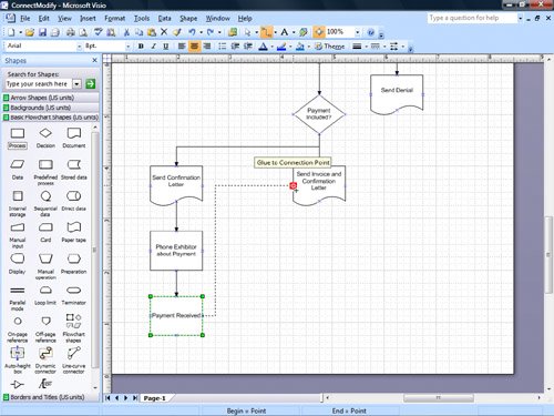
|
|
23. |
Release the mouse button. |
|
24. |
On the Standard toolbar, click the Pointer Tool button. Pointer Tool
|
|
25. |
Position the pointer over the midpoint on the left segment of the connector you just drew. 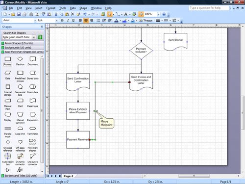
|
|
26. |
Drag the midpoint a little to the right to move that segment of the connector. 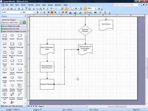
Tip Connectors have a shortcut menu just as other shapes do. You can use the commands on a connector's shortcut menu to access commands that are unique to connectors, such as the Right-Angle Connector, Straight Connector, and Curved Connector commands. Right-click a connector to display its shortcut menu. |
|
27. |
Move the Payment Received shape up and to the right to position it below the Send Invoice and Confirmation Letter shape. 
|
|
28. |
Select the connector between the Payment Received shape and the Send Invoice and Confirmation Letter shape. |
|
29. |
Place the pointer over the red connector endpoint on the Send Invoice and Confirmation Letter shape. 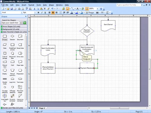
|
|
30. |
Drag the endpoint to the bottom connection point on the Send Invoice and Confirmation Letter shape. 
|
|
31. |
Place the pointer over the red connector endpoint on the Payment Received shape. |
|
32. |
Drag the endpoint to the top connection point on the Payment Received shape. 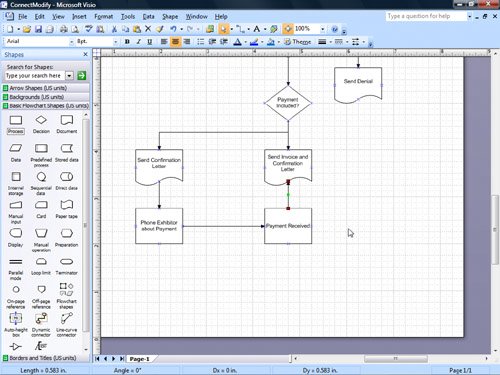
Save
|
|
33. |
On the Standard toolbar, click Save to save your changes to the diagram. |
 key to restrict its movement.
 key to enter the text mode, and then press the
  key to delete the text from the connector.
 key to exit the text mode.

CLOSE the ConnectModify file.
Quick Reference
Getting Started with Visio 2007
- Getting Started with Visio 2007
- Starting Diagrams by Using Templates
- Working Within the Visio Environment
- Customizing the Visio Environment
- Getting Visio and Diagram Help
- Key Points
Adding Shapes to Diagrams
- Adding Shapes to Diagrams
- Working with 1-D and 2-D Shapes
- Adding Text to Shapes and the Drawing Page
- Moving, Sizing, Rotating, and Copying Shapes
- Working with Groups
- Finding Shapes for Diagrams
- Inserting Pictures into Diagrams
- Key Points
Formatting Shapes and Diagrams
- Formatting Shapes and Diagrams
- Formatting Individual Shapes
- Adding Decorative Elements to Diagrams
- Applying Themes to Entire Diagrams
- Key Points
Connecting Shapes
- Connecting Shapes
- Connecting Shapes in Flowcharts
- Modifying Shape Connections
- Changing the Layout of Connected Shapes
- Key Points
Creating Project Schedules
- Creating Project Schedules
- Creating Timelines to View Projects at a Glance
- Exporting Timelines to Create Gantt Charts
- Tracking Project Details with Gantt Charts
- Key Points
Creating Organization Charts
- Creating Organization Charts
- Importing Data to Create Organization Charts
- Storing and Displaying Employee Information in Organization Charts
- Customizing the Layout of Organization Charts
- Key Points
Laying Out Office Spaces
- Laying Out Office Spaces
- Creating Scaled Office Spaces
- Adding Door, Window, and Furniture Shapes to Office Layouts
- Organizing Shapes in Office Layouts by Using Layers
- Key Points
Creating Network Diagrams
- Creating Network Diagrams
- Connecting Shapes in Network Diagrams
- Storing Information with Network Shapes
- Creating Network Reports
- Key Points
Glossary
About the Authors
Choose the Right Book for You
EAN: 2147483647
Pages: 81
