Cisco Multiservice IP-to-IP Gateway
The Cisco Multiservice IPIPGW facilitates simple and cost-effective connectivity between independent VoIP and video networks. Designed to meet enterprise and service provider SBC needs, the Cisco Multiservice IPIPGW is an integrated Cisco IOS application that runs on the following platforms:
- Cisco 2800 series integrated services routers
- Cisco 3800 series integrated services routers
- Cisco 2600XM series multiservice platforms
- Cisco 2691 routers
- Cisco 3700 series routers
- Cisco 7200VXR series routers
- Cisco 7301 routers
- Cisco AS5350XM and AS5400XM universal gateways
The IPIPGW images support not only IPIPGW functionality, but also a regular TDM gateway and gatekeeper functionality. The IPIPGW images are special images, which are integrated along with the routing, switching, and security features that are available in the regular Cisco IOS images.
Deploying IPIPGWs has three prerequisites:
- A supported Cisco router platform
- A Cisco Multiservice IPIPGW Cisco IOS imageINT VOICE/VIDEO, IPIP GW, or TDMIP GW
- Cisco integrated voice video license: gatekeeper IPIPGW feature license
Architecture
On a regular Cisco voice gateway, one call leg is a TDM connection on which the call is originated or terminated. The other call leg could be a VoIP call based on any VoIP protocol. With the IPIPGW, a single voice call has two VoIP call legs. The originating call leg is matched on the incoming VoIP dial peer and terminated at the IPIPGW. The second call leg is reoriginated based on the outgoing VoIP dial peer.
Figure 18-1 illustrates the IPIPGW architecture, which is based on the back-to-back user agent (B2BUA), which is SIP, or the back-to-back gateway (B2BGW), which is H.323.
Figure 18-1. IPIPGW Architecture
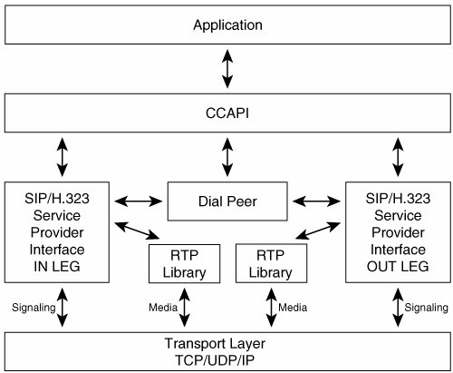
The IPIPGW implementation leverages Cisco voice gateway architecture. The main difference between the voice gateway and the IPIPGW is that no telephony service provider interface (SPI) or telephony signaling stack exists in case of IPIPGW. The IPIPGW has two IP legs for a given voice call, whereas the TDM-IP gateway has one telephony and one IP leg for a given TDM-IP call.
When a VoIP call arrives at the IPIPGW, it is matched at the configured inbound dial peer. The particular VoIP SPI (such as H.323 or SIP) processes the call and informs the application, which in turn routes the call using the configured outbound dial peer. The two SPIs talk using the application layer for the signaling messages. For capability, media address, and port exchanges, the SPI communicates directly or by using the Call Control API (CCAPI) layer.
Each IP leg has a corresponding Real-Time Transport Protocol (RTP) instance that is associated with it for media flow-through. The media stream that is originating from the IPIPGW carries the IP address and the port number of the IPIPGW.
Note
The only changes in the media stream are the IP address and port number. For media flow around calls, media flows directly between endpoints; therefore, you will not see RTP instances on the IPIPGW.
Media-Handling Modes
You can handle the passing of media in two ways:
- Media flow-through
- Media flow-around
Figure 18-2 illustrates the media-handling modes that are supported on the IPIPGW.
Figure 18-2. Media Handling Modes
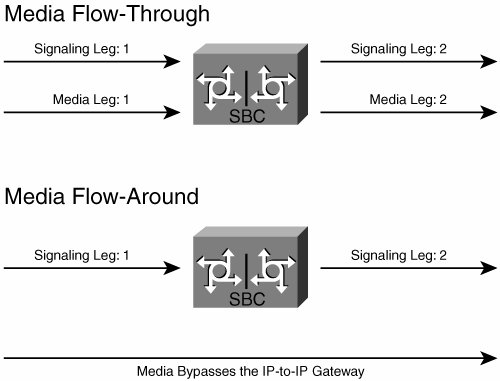
- Media flow-through In media flow-through, the media stream passes through the IPIPGW, as shown in the top example of Figure 18-2. The IP address in the RTP packet is rewritten, with the IPIPGW inserting its own IP address. This provides complete privacy of the endpoints that are generating and terminating the call. None of the parties involved in the conversation would know the IP address of the other party. Both endpoints see only the IP address of the IPIPGW that is sending and receiving the RTP packets. Media flow-through is the default mode for media handling.
- Media flow-around If media flow-around is configured, the media stream bypasses the IPIPGW and flows directly between the originating and terminating endpoints. This is shown in the bottom example of Figure 18-2. In this case, both the endpoints that are involved in the call would know the IP address of the other endpoint.
Protocol Support
The IPIPGW supports the following VoIP call combinations:
- SIP-to-SIP
- H.323-to-H.323
- H.323-to-SIP interworking
SIP Networks
For SIP networks, the Cisco IPIPGW functions as a B2BUA. It receives a SIP request, reformulates the request, and then sends it as a new request. The responses that the terminating endpoint sends to the request are also reformulated and sent back in the opposite direction. Therefore, the Cisco IPIPGW can sit between two SIP networks without either party knowing the uniform resource identifier (URI), IP address, or any other information of the other party.
To achieve this, the B2BUA reformulates a request with entirely new From, Via, Contact, Call ID, and Session Description Protocol (SDP) media information. The B2BUA also removes any other SIP header fields that might contain information about the calling party. When the B2BUA returns a response, it also changes the contact and SDP media information from the called party. The modified SDP points to the B2BUA, which then forwards RTP media packets from the called party to the calling party and vice versa. Thus, neither endpoint learns any identifying information about the other party during the session establishment.
H.323 Networks
In H.323 networks, the Cisco IPIPGW also functions as a B2BGW, or a terminator and reoriginator of voice, fax, or video calls. No DSPs are required for calls using the same codec, which provides better quality voice calls because hardly any delay is added for the RTP stream. DSPs are required only if you need to transcode between two codecs, such as G.711ulaw and G.729r8.
Protocol Interworking
Because the Cisco IPIPGW terminates and reoriginates VoIP calls, it can handle different VoIP protocols on each leg. This provides a valuable capability when protocol-disparate networks need to talk to one another. The Cisco Multiservice IPIPGW does protocol interworking between H.323 and SIP for voice and fax calls.
This provides flexibility to customers who are connecting their Cisco CallManager H.323 network to a VoIP service provider who offers SIP services. It also enables customers who want to migrate from H.323-based networks to SIP-based networks. With the media flowing through the gateway, complete network hiding for both signaling and media is achieved. Also, if the enterprise is using one codec, such as G.711ulaw, and the SIP VoIP service provider is using G.729r8, transcoding between these codecs is supported for the protocol interworking scenarios. Supplementary services between H.323 trunks of the Cisco CallManager and SIP service provider are supported. The H.323 trunk needs to configure a media termination point (MTP) so that services such as call hold/resume, call transfer, and so on can be used.
Part I: Voice Gateways and Gatekeepers
Gateways and Gatekeepers
- Gateways and Gatekeepers
- The Role of Voice Gateways
- The Role of Voice Gatekeepers
- The Role of IP-to-IP Gateways
- Introduction to Voice Protocols
- Call Control Agents
- Deployment Scenarios
- Case Study: Introduction
- Chapter Review Questions
Part II: Gateways
Media Gateway Control Protocol
- Media Gateway Control Protocol
- Introduction to MGCP
- MGCP Operation
- Call Flow with MGCP
- Dial Plan Considerations
- Implementing MGCP Gateways
- Securing MGCP Gateways
- Troubleshooting Tools
- Case Study: Configuring an MGCP Gateway
- Review Questions
H.323
- H.323
- H.323 Specifications
- H.323 Network Components
- Call Flow
- H.323 Protocol Pros and Cons
- When to Use H.323
- Dial Plan Considerations
- Implementing H.323 Gateways
- Securing H.323 Gateways
- Troubleshooting Tools
- Case Study: Configuring an H.323 Gateway
- Review Questions
Session Initiation Protocol
- Session Initiation Protocol
- Description of SIP
- SIP Call Flow
- SIP Pros and Cons
- When to Use SIP
- Dial Plan Considerations
- Implementing SIP Gateways
- Securing SIP Gateways
- Allowing H.323 to SIP Connections
- Troubleshooting Tools
- Case Study: Configuring SIP Between a Gateway and CallManager 5.x
- Review Questions
Circuit Options
Connecting to the PSTN
- Connecting to the PSTN
- PSTN Circuit Selection Overview
- Analog Trunks
- Digital Trunks
- Case Study: Add an E1 R2 Connection to the Leeds Gateway
- Review Questions
Connecting to PBXs
- Connecting to PBXs
- Analog Trunks
- Digital Trunks
- Configuring Transparent Common Channel Signaling
- Case Study: Implementing a Cisco Voice Gateway at the Shanghai Office
- Review Questions
Connecting to an IP WAN
- Connecting to an IP WAN
- Applications for Connecting to an IP WAN
- Design Considerations
- Quality of Service
- Providing Fax and Modem Services
- Security
- Case Study: Using a T1 Link as a Tie Line
- Review Questions
Dial Plans
- Dial Plans
- Numbering Plans
- Overlapping Numbering Plans
- Building a Scalable Dial Plan
- Dial Peers
- Dial Peer Matching
- Case Study: Configuring PSTN Access
- Review Questions
Digit Manipulation
- Digit Manipulation
- Basic Digit Manipulation
- Number Expansion
- Voice Translation Rules and Profiles
- Manipulating Caller ID
- Order of Operation in Digit Manipulation
- Troubleshooting Digit Manipulation
- Case Study
- Review Questions
Influencing Path Selection
- Influencing Path Selection
- Hunt Groups
- Using Trunk Groups
- Tail-End Hop-Off
- Call Admission Control
- POTS-to-POTS Call Routing Considerations
- Case Study: Implementing Gateway-Controlled RSVP
- Review Questions
Configuring Class of Restrictions
- Configuring Class of Restrictions
- COR Overview
- COR Operation
- Implementing COR
- Assigning COR Lists with SRST
- Assigning COR Lists with Cisco CallManager Express
- Restricting Inbound Calls
- Case Study: Implementing COR for Miami
- Review Questions
SRST and MGCP Gateway Fallback
- SRST and MGCP Gateway Fallback
- SRST Overview
- Configuring SRST
- Dial Plan Considerations
- SRST Features
- SIP SRST
- Call Preservation
- Secure SRST
- MGCP Gateway Fallback
- Configuring MGCP Gateway Fallback
- Verifying and Troubleshooting SRST
- Verifying and Troubleshooting MGCP Gateway Fallback
- Case Study: Integrating SRST with an Analog Voice-Mail System
- Review Questions
DSP Resources
- DSP Resources
- Need for DSP Resources
- Determining the DSP Resources Required
- Configuring DSP Resources
- Transcoding for CallManager Express
- Case Study: Add DSP Resources to the Miami Gateway
- Review Questions
Using Tcl Scripts and VoiceXML
- Using Tcl Scripts and VoiceXML
- Tcl IVR and VoiceXML Application Overview
- Sample Applications
- Downloading Tcl Scripts from Cisco.com
- Configuring the Gateway to Use a Tcl Script
- Implementing the AA Tcl Script
- Creating Audio Files
- Restrictions and Caveats
- Case Study: Implementing ACD Application
- Review Questions
Part III: Gatekeepers
Deploying Gatekeepers
- Deploying Gatekeepers
- Gatekeeper Functionality
- Gatekeeper Signaling
- E.164 Number Resolution
- Call Admission Control
- Gatekeeper Deployment Models
- Gatekeepers with CallManager
- Security with Gatekeepers
- Review Questions
Gatekeeper Configuration
- Gatekeeper Configuration
- Configuring Basic Gatekeeper Functionality
- Multiple Gatekeeper Configurations
- Configuring Directory Gatekeepers
- Troubleshooting Gatekeepers
- CallManager and Gatekeepers
- Gatekeeper Redundancy
- Configuring Resource Availability Indicator
- Configuring Gatekeeper Security
- Case Study: Deploying Gatekeepers to Assist in Migration to VoIP
- Review Questions
Part IV: IP-to-IP Gateways
Cisco Multiservice IP-to-IP Gateway
- Cisco Multiservice IP-to-IP Gateway
- IP-to-IP Gateway Overview
- Cisco Multiservice IP-to-IP Gateway
- Basic Configuration
- IP-to-IP Gateway Features
- Case Study: Providing Enterprise VoIP Trunking to VoIP Service of the Service Provider
- Review Questions
Appendix A. Answers to Chapter-Ending Review Questions
Index
EAN: 2147483647
Pages: 218
- Chapter II Information Search on the Internet: A Causal Model
- Chapter VIII Personalization Systems and Their Deployment as Web Site Interface Design Decisions
- Chapter XI User Satisfaction with Web Portals: An Empirical Study
- Chapter XII Web Design and E-Commerce
- Chapter XV Customer Trust in Online Commerce
