Implementing H.323 Gateways
Before you enable H.323, configure the router with a hostname, IP addressing, and routing information. Give careful thought and planning to the dial peer configurations and settings you will use. The following are some common settings to specify:
- Codec
- DTMF Relay method
- Dial peer preference
- VAD
- QoS DSCP values
- Call progress indicators
- Fax relay information
- Direct-inward-dial
Voice Class Configuration
You can create a voice class to apply configurations to specific dial peers or voice ports. Several types of configurations are possible. This section looks at two: codec and H.323 parameters.
A codec voice class allows you to control the codec negotiation by specifying which codecs will be offered, and a preference value for each codec. Use the voice class codec tag# command to create the voice class. Then list codecs and preferences with the codec preference priority codec-type command. The priority value range is 1 to 14, with 1 being the highest priority. Apply the voice class to a dial peer with the voice-class codec tag# command.
The voice class h323 tag# command creates a voice class that allows you to configure the items shown in Table 3-1. The exact commands available depend on your Cisco IOS version and feature set.
|
Command |
Use |
|---|---|
|
call |
Specifies H.323 fast or slow start for a particular dial peer |
|
ccm-compatible |
For CallManager connections, allows CallManager-specific behavior |
|
encoding |
Configures H.323 ASN.1 encoding options |
|
H225 |
Includes H225 timeout values. Timeout has three options:
|
|
H245 |
Configures H245 capabilities settings |
|
telephony-service |
Used for CallManager Express (CME) H.323 connections |
Example 3-1 shows a basic H.323 dial peer configuration. A voice class has been created to control the codecs that are negotiated and their preferred order.
NYCgateway(config)#voice class codec 1 NYCgateway(config-class)#codec preference 1 g729r8 NYCgateway(config-class)#codec preference 2 g729br8 NYCgateway(config-class)#codec preference 3 g711ulaw ! NYCgateway(config)#dial-peer voice 100 voip NYCgateway(config-dial-peer)#incoming called-number . NYCgateway(config-dial-peer)#no vad ! NYCgateway(config-dial-peer)#dial-peer voice 10 voip NYCgateway(config-dial-peer)#destination-pattern 1... NYCgateway(config-dial-peer)#session target ipv4:10.1.10.10 NYCgateway(config-dial-peer)#no vad NYCgateway(config-dial-peer)#voice-class codec 1 ! NYCgateway(config-dial-peer)#dial-peer voice 900 pots NYCgateway(config-dial-peer)#incoming called-number . NYCgateway(config-dial-peer)#direct-inward-dial ! NYCgateway(config)#dial-peer voice 9 pots NYCgateway(config-dial-peer)#destination-pattern 9T NYCgateway(config-dial-peer)#direct-inward-dial NYCgateway(config-dial-peer)#preference 1 NYCgateway(config-dial-peer)#port 3/0:23 ! NYCgateway(config-dial-peer)#dial-peer voice 99 pots NYCgateway(config-dial-peer)#destination-pattern 9T NYCgateway(config-dial-peer)#direct-inward-dial NYCgateway(config-dial-peer)#preference 2 NYCgateway(config-dial-peer)#port 1/0/0 |
In this example, a voice class and several dial peers are configured.
- A voice class was configured to list the preferred order for codecs to be negotiated.
- Dial peer 100 is a default dial peer for incoming VoIP traffic. The incoming called-number command tells the router to look for a match to the dialed number identification service (DNIS) number of the incoming call. In this example, the command uses the . (period) wildcard, which matches all called numbers. VAD is turned off for these calls.
- Dial peer 10 forwards calls for IP phones to the CallManager (IP address 10.1.10.10). The IP phone number range is 1000 through 1999, matched by the destination pattern 1... using wildcards for the last three digits. VAD is turned off for these calls, DTMF Relay is specified, and the codec voice class is associated with this dial peer.
- Dial peer 900 is a default dial peer for calls that come in from the PSTN. It matches all called numbers with the . (period) wildcard and enables direct inward dial. This tells the router not to send a secondary dial tone to the caller, but to collect all the incoming digits.
- Dial peer 9 is the preferred peer for all calls to the PSTN. The destination pattern is 9T. This assumes that users dial a 9 for outside calls. The "T" tells the router to expect a variable length dial string and to wait for the interdigit timeout to expire before matching this dial peer. 9T matches emergency calls in addition to regular ones, but you might want to explicitly configure matches for emergency numbers to avoid waiting for the interdigit timeout. This dial peer has a preference value of 1, and it is associated with the PRI port.
- Dial peer 99 is also a POTS dial peer, and it, too, has a destination pattern of 9T and direct inward dial configured. It has a preference value of 2, so it will be used only if dial peer 9 is unavailable (lower preference wins). This dial peer is associated with FXO port 1/0/0.
Note
Dial peers are discussed in more detail in Chapter 9, "Dial Plans," and in the CVoice course.
Voice Service VoIP Configuration
The voice service commands cover some of the same parameters as voice classes, but these commands apply to the gateway as a whole. An individual gateway could have both voice service configuration and voice class configuration. In that case, configuration that is applied to an individual dial peer takes precedence over global configuration.
Four configuration submodes exist: POTS, Voice over ATM (VoATM), Voice over Frame Relay (VoFR), and VoIP. This section covers some of the VoIP options. The command to enter voice service configuration mode is given at the global configuration prompt: voice service {pots | voatm | vofr | voip}.
One use of the voice service configuration is call redirection. Consider the network shown in Figure 3-3. GW1 has a PRI line and is in a CallManager route group. GW2 has a couple of POTS lines.
Figure 3-3. Allowing H.323 Call Redirection
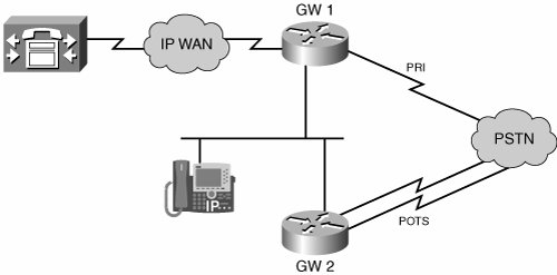
When the IP phone needs to send a call to the PSTN, the CallManager directs it to GW1. But suppose that the PRI line is full. The call could go out over one of the POTS lines on GW2, but the CallManager will not redirect it. You can configure the router to do so, however. On GW1, create a VoIP dial peer for PSTN numbers, with a higher preference value so that it is less preferred, and a session target of GW2. On Cisco IOS Software versions later than Release 12.3(7)T, you must enable this capability with the allow-connections h323 to h323 command:
GW1(config)#voice service voip
GW1(conf-voi-serv)#allow-connections h323 to h323
The allow-connections command allows a Cisco router or CME to route between VoIP dial peers. You might use it when hairpinning or redirecting calls, as shown. Other options include the allow-connections h323 to sip command and the allow-connections sip to h323 command.
Call survivability can be an issue with H.323. By default, an H.323 gateway exchanges H.225 keepalives with CallManager. When those keepalives fail, active calls are torn down. H.323 gateways can use SRST for backup when the CallManager is unreachable. The CallManager resets all active calls when it resumes the connection to the H.323 gateway. To prevent active calls from being terminated when the CallManager becomes unreachable, turn off H.225 keepalives between the gateway and CallManager. You do this in the h323 submode of the voice service voip command, as the following code shows:
GW1(config)#voice service voip
GW1(conf-voi-serv)#h323
GW1(conf-serv-h323)#no h225 timeout keepalive
You can stop the H.323 service in this submode by giving the following commands. You can then restart it in the same mode with the no call service stop command:
GW1(config)#voice service voip
GW1(conf-voi-serv)#h323
GW1(conf-serv-h323)#call service stop
Finally, you can control Fast Start globally. (Use a Voice Class to configure it for specific dial peers.)
GW1(config)#voice service voip
GW1(conf-voi-serv)#h323
GW1(conf-serv-h323)#call start slow
Toll Bypass
Companies that have their business in different areas might find that they spend a significant amount of money on long-distance calls between those locations. One way to minimize that cost is to use VoIP for intracompany calls. With toll bypass, calls between company locations are sent over the IP network as VoIP when bandwidth is available, and they are routed over the PSTN when no bandwidth is available. Calls can be sent over the WAN using Frame Relay or ATM, or over direct connections, such as T1 links. Voice typically shares bandwidth with data in this situation. Therefore, you must give careful consideration to QoS.
If you are using a multisite CallManager network, you are already doing something similar, with CallManager controlling the routing of intracompany calls over the WAN. However, even companies that have a PBX and analog phones can use toll bypass. They can connect the PBX to a router using standard analog or digital interfaces. The router then packetizes the voice traffic and routes it over the WAN to its peer gateway. The terminating gateway receives the IP voice traffic and, if it is also connected to a PBX, sends the call through the PBX to analog phones.
Note
Call Admission Control (CAC) and QoS become critical in this type of network. For more information, see Chapter 7, "Connecting to PBXs," Chapter 8, "Connecting to an IP WAN," and Chapter 11, "Influencing Path Selection."
Example 3-2 shows a voice gateway router that is configured to enable toll bypass. The Shanghai gateway router has one PRI to the PSTN (port 1/0) and another PRI to the PBX (port 2/0). It is configured to use toll bypass for its traffic to the New York office. New York also has a router that is connected to a PBXthe two routers do toll bypass between each other. Only the Shanghai configuration is shown in this example. Of course, the company needs to configure the router at the New York office similarly. This network is diagramed in Figure 3-3.
ShanghaiGW(config)#dial-peer voice 212 voip ShanghaiGW(config-dial-peer)#destination-pattern 121255521.. ShanghaiGW(config-dial-peer)#session target ipv4:10.1.25.1 ! ShanghaiGW(config)#dial-peer voice 213 pots ShanghaiGW(config-dial-peer)#destination-pattern 121255521.. ShanghaiGW(config-dial-peer)#preference 1 ShanghaiGW(config-dial-peer)#direct-inward-dial ShanghaiGW(config-dial-peer)#forward-digits all ShanghaiGW(config-dial-peer)#port 1/0:23 ! ShanghaiGW(config-dial-peer)#dial-peer voice 21 pots ShanghaiGW(config-dial-peer)#destination-pattern 2155541.. ShanghaiGW(config-dial-peer)#direct-inward-dial ShanghaiGW(config-dial-peer)#forward-digits 4 ShanghaiGW(config-dial-peer)#port 2/0:23 |
Dial peers 212 and 213 have the same destination pattern for a range of phone numbers at the New York office. Dial peer 212 will be preferred, because it has the default preference value of 0, and dial peer 213 has been given a preference of 1. Calls to the New York office will be routed over the WAN if possible, as a toll-free call. Those calls will go over the PSTN only if the WAN is down or if bandwidth is insufficient for the call.
The IP address in the dial peer 212 session target is the New York office router. The port that is specified in dial peer 213 is the PRI to the PSTN. Dial peer 21 forwards all traffic that is bound to the analog phones out the PRI to the PBX. The forward-digits 4 command instructs the router to send only the last four digits of the called number to the PBX.
Figure 3-4 shows the network between the New York and the Shanghai offices. Toll bypass is configured on the two routers that are connected to PBXs at each location, to enable them to send interoffice calls over the IP WAN.
Figure 3-4. Toll Bypass

Defining H.323 Gateways on CallManager
If the gateway will be part of a Cisco Unified Communications system, you need to configure it to peer with CallManager. You must still configure the dial peers and any dial peer options you need. Configure an additional VoIP dial peer for routing calls that are bound to other phones in the cluster. List the IP address of the CallManager as its session target. The destination pattern will depend on your dial plan, but you should specify intracluster calls. If your dial plan is complex, you might need several VoIP dial peers to cover it.
After you configure the gateway, configure CallManager to recognize and use it.
|
Step 1. |
The CallManager configuration for an H.323 gateway is fairly simple. In CallManager Administration, go to the Device menu and select Gateway from the drop-down list. When the Find and List Gateways page opens, select the Add a New Gateway link. |
|
Step 2. |
Figure 3-5 shows the next page. Select H.323 Gateway from the drop-down list next to Gateway Type. Notice that the server automatically fills in the Device Protocol box with H.225. Click the Next button. Figure 3-5. Adding an H.323 Gateway to CallManager 
|
|
Step 3. |
On the next screen, shown in Figure 3-6, you enter information about the gateway. Figure 3-6. Configuring the Gateway on CallManager 
For Device Name, enter the IP address of the router. Notice that only one IP address is allowed. If the router might use multiple interfaces to communicate with its CallManager, you need to tell the router which one to use as the source of its messages (possibly a loopback interface). Use the h323-gateway voip bind srcaddr ip-address command, under interface configuration mode. Add a description and select the CallManager device pool to which the gateway will belong. The Location field is used to control the number of calls allowed to a site, to ensure that each call has enough bandwidth. This is typically used with a remote gateway. This page has many other options. Check your CallManager documentation for further explanation. When you are finished, click the Insert button. After the screen refreshes, reset the gateway. |
|
Step 4. |
Verify that the gateway has been defined on the CallManager by doing a search on the Find and List Gateways page of CallManager Administration. You should see the gateway listed. The gateway will show "Not Registered," which is normal because the H.323 gateway treats the CallManager as its peer. |
Redundancy
In a cluster with multiple CallManagers, the gateway needs to be able to use alternates if the primary one is unavailable. You can set this up by creating VoIP dial peers pointing to each CallManager. Use a preference value under each dial peer to determine the order in which the CallManagers are used. The default preference is 0; the lowest preference wins.
NYCgateway(config)#dial-peer voice 11 voip
NYCgateway(config-dial-peer)#session target ipv4:10.1.10.11
NYCgateway(config-dial-peer)#preference 2
You might need to adjust the default timers when using multiple CallManagers, especially if the gateway has a PRI connection for inbound calls. When a call comes in that should be forwarded to a CallManager, the router attempts to set up an H.225 TCP session to its preferred VoIP dial peer. The TCP session must time out before it will try another dial peer. This takes 15 seconds by default. ISDN Q.931 has a Call Proceeding timeout of 10 seconds. A call that comes in over a PRI line will time out before the router can fail over to an alternate CallManager. Even without a PRI connection, 15 seconds might be longer than you want to wait.
To remedy this, change the H.225 TCP session establishment timer. The voice class h323 10 command creates a voice class in global configuration mode that reduces the timer to three seconds:
NYCgateway(config)#voice class h323 10
NYCgateway(configs-class)#h225 timeout tcp establish 3
Apply that voice class under the dial peers pointing to redundant CallManagers:
NYCgateway(config)#dial-peer voice 1 voip
NYCgateway(config-dial-peer)#session target ipv4:10.1.10.10
NYCgateway(config-dial-peer)#voice-class h323 10
DTMF Relay
DTMF tones are created when a digit is dialed on a telephone. By default, the gateway sends these tones within the voice RTP stream. When voice is sent uncompressed, these tones arrive in their original state. However, when voice is compressed, such as with the G.729 codec, the tones might be distorted, or part of the signal might be lost. DTMF Relay addresses this by separating these tones from the rest of the voice and then sending them in a different way.
H.323 gateways have four different ways of sending these tones: the Cisco proprietary method, RTP-NTE, H.245 Alphanumeric, and H.245 Signal.
- Cisco proprietary method Sends the tones in the same RTP stream as voice, but they are coded as payload type 121 to enable the receiver to identify them as DTMF signals. To use this method, both the originating and terminating gateways must be Cisco devices.
- RTP-NTE Uses a method specified in RFC 2833 to send DTMF tones within the RTP stream, in a special Named Telephony Event (NTE) packet. The use of this method and the payload type value is negotiated on a call-by-call basis.
- H.245 Alphanumeric Is specified by the ITU-T H.245 standard. Tones are sent over the H.245 signaling channel, rather than in-band with voice traffic. H.245 transmits DMTF tones to the receiving gateway as the ASCII character it represents (1, 2, 3, and so on). It does not send tone-length information. Each tone is assumed to last 500 milliseconds (ms). All H.323 gateways must support this type of DTMF Relay.
- H.245 Signal Addresses a potential problem with H.245 Alphanumeric. It does not pass along the length of a tone. Sometimes it is important to know how long a particular tone lastedthat is, how long a keypad button was held down. You might notice this when placing multiple calls using a calling card. With the company-provided calling card of the author, you can avoid having to re-enter the card number by holding down the # key for two seconds. H.245 Signal DTMF Relay sends information about the tone duration along with its alphanumeric representation. Support for H.245 Signal is optional in H.323 gateways.
The Cisco method and RTP-NTE send the tones in-band, and both H.245 methods send them out-of-band. Gateways negotiate the type of DTMF Relay to be used during call establishment.
You configure DTMF Relay under the dial peer on H.323 gateways. If no method is configured, the tones are sent in-band with the voice stream. To configure a specific type of DTMF Relay, use the dtmf-relay [cisco-rtp] [rtp-nte] [h245-alphanumeric] [h245-signal] command.
Example 3-3 shows an H.323 gateway that is configured for H.245 alphanumeric DTMF Relay. It also shows that you can list multiple types of DTMF Relay in the command, to support the capabilities of different terminating gateways.
|
[View full width] NYCgateway(config)#dial-peer voice 10 voip NYCgateway(config-dial-peer)#dtmf-relay h245-alphanumeric ? cisco-rtp Cisco Proprietary RTP h245-signal DTMF Relay via H245 Signal IE rtp-nte RTP Named Telephone Event RFC 2833 NYCgateway(config-dial-peer)#dtmf-relay h245-alphanumeric h245-signal rtp-nte cisco-rtp NYCgateway(config-dial-peer)#^Z NYCgateway#show run ![output omitted] dial-peer voice 10 voip session target ipv4:10.1.10.10 dtmf-relay cisco-rtp rtp-nte h245-signal h245-alphanumeric rtp-nte cisco-rtp NYCgateway(config-dial-peer)#^Z NYCgateway#show run ![output omitted] dial-peer voice 10 voip session target ipv4:10.1.10.10 dtmf-relay cisco-rtp rtp-nte h245-signal h245-alphanumeric
|
In Example 3-3, the DTMF Relay methods were entered in one order, but the output of the show run commands shows them in a different order. If you specify multiple methods, the Relay method is negotiated in the order of priority shown in the show run output:
- Cisco-RTP
- RTP-NTE
- H.245 Signal
- H.245 Alphanumeric
Part I: Voice Gateways and Gatekeepers
Gateways and Gatekeepers
- Gateways and Gatekeepers
- The Role of Voice Gateways
- The Role of Voice Gatekeepers
- The Role of IP-to-IP Gateways
- Introduction to Voice Protocols
- Call Control Agents
- Deployment Scenarios
- Case Study: Introduction
- Chapter Review Questions
Part II: Gateways
Media Gateway Control Protocol
- Media Gateway Control Protocol
- Introduction to MGCP
- MGCP Operation
- Call Flow with MGCP
- Dial Plan Considerations
- Implementing MGCP Gateways
- Securing MGCP Gateways
- Troubleshooting Tools
- Case Study: Configuring an MGCP Gateway
- Review Questions
H.323
- H.323
- H.323 Specifications
- H.323 Network Components
- Call Flow
- H.323 Protocol Pros and Cons
- When to Use H.323
- Dial Plan Considerations
- Implementing H.323 Gateways
- Securing H.323 Gateways
- Troubleshooting Tools
- Case Study: Configuring an H.323 Gateway
- Review Questions
Session Initiation Protocol
- Session Initiation Protocol
- Description of SIP
- SIP Call Flow
- SIP Pros and Cons
- When to Use SIP
- Dial Plan Considerations
- Implementing SIP Gateways
- Securing SIP Gateways
- Allowing H.323 to SIP Connections
- Troubleshooting Tools
- Case Study: Configuring SIP Between a Gateway and CallManager 5.x
- Review Questions
Circuit Options
Connecting to the PSTN
- Connecting to the PSTN
- PSTN Circuit Selection Overview
- Analog Trunks
- Digital Trunks
- Case Study: Add an E1 R2 Connection to the Leeds Gateway
- Review Questions
Connecting to PBXs
- Connecting to PBXs
- Analog Trunks
- Digital Trunks
- Configuring Transparent Common Channel Signaling
- Case Study: Implementing a Cisco Voice Gateway at the Shanghai Office
- Review Questions
Connecting to an IP WAN
- Connecting to an IP WAN
- Applications for Connecting to an IP WAN
- Design Considerations
- Quality of Service
- Providing Fax and Modem Services
- Security
- Case Study: Using a T1 Link as a Tie Line
- Review Questions
Dial Plans
- Dial Plans
- Numbering Plans
- Overlapping Numbering Plans
- Building a Scalable Dial Plan
- Dial Peers
- Dial Peer Matching
- Case Study: Configuring PSTN Access
- Review Questions
Digit Manipulation
- Digit Manipulation
- Basic Digit Manipulation
- Number Expansion
- Voice Translation Rules and Profiles
- Manipulating Caller ID
- Order of Operation in Digit Manipulation
- Troubleshooting Digit Manipulation
- Case Study
- Review Questions
Influencing Path Selection
- Influencing Path Selection
- Hunt Groups
- Using Trunk Groups
- Tail-End Hop-Off
- Call Admission Control
- POTS-to-POTS Call Routing Considerations
- Case Study: Implementing Gateway-Controlled RSVP
- Review Questions
Configuring Class of Restrictions
- Configuring Class of Restrictions
- COR Overview
- COR Operation
- Implementing COR
- Assigning COR Lists with SRST
- Assigning COR Lists with Cisco CallManager Express
- Restricting Inbound Calls
- Case Study: Implementing COR for Miami
- Review Questions
SRST and MGCP Gateway Fallback
- SRST and MGCP Gateway Fallback
- SRST Overview
- Configuring SRST
- Dial Plan Considerations
- SRST Features
- SIP SRST
- Call Preservation
- Secure SRST
- MGCP Gateway Fallback
- Configuring MGCP Gateway Fallback
- Verifying and Troubleshooting SRST
- Verifying and Troubleshooting MGCP Gateway Fallback
- Case Study: Integrating SRST with an Analog Voice-Mail System
- Review Questions
DSP Resources
- DSP Resources
- Need for DSP Resources
- Determining the DSP Resources Required
- Configuring DSP Resources
- Transcoding for CallManager Express
- Case Study: Add DSP Resources to the Miami Gateway
- Review Questions
Using Tcl Scripts and VoiceXML
- Using Tcl Scripts and VoiceXML
- Tcl IVR and VoiceXML Application Overview
- Sample Applications
- Downloading Tcl Scripts from Cisco.com
- Configuring the Gateway to Use a Tcl Script
- Implementing the AA Tcl Script
- Creating Audio Files
- Restrictions and Caveats
- Case Study: Implementing ACD Application
- Review Questions
Part III: Gatekeepers
Deploying Gatekeepers
- Deploying Gatekeepers
- Gatekeeper Functionality
- Gatekeeper Signaling
- E.164 Number Resolution
- Call Admission Control
- Gatekeeper Deployment Models
- Gatekeepers with CallManager
- Security with Gatekeepers
- Review Questions
Gatekeeper Configuration
- Gatekeeper Configuration
- Configuring Basic Gatekeeper Functionality
- Multiple Gatekeeper Configurations
- Configuring Directory Gatekeepers
- Troubleshooting Gatekeepers
- CallManager and Gatekeepers
- Gatekeeper Redundancy
- Configuring Resource Availability Indicator
- Configuring Gatekeeper Security
- Case Study: Deploying Gatekeepers to Assist in Migration to VoIP
- Review Questions
Part IV: IP-to-IP Gateways
Cisco Multiservice IP-to-IP Gateway
- Cisco Multiservice IP-to-IP Gateway
- IP-to-IP Gateway Overview
- Cisco Multiservice IP-to-IP Gateway
- Basic Configuration
- IP-to-IP Gateway Features
- Case Study: Providing Enterprise VoIP Trunking to VoIP Service of the Service Provider
- Review Questions
Appendix A. Answers to Chapter-Ending Review Questions
Index
EAN: 2147483647
Pages: 218
