Implementing SIP Gateways
Configuring a SIP gateway can be as simple as configuring SIP VoIP dial peers or as complex as tweaking SIP settings and timers. Gateway SIP configuration is done in three basic places: on dial peers, under SIP UA configuration mode, and under voice service VoIP configuration mode. The following sections discuss the types of configuration you can accomplish in each mode.
SIP Dial Peer Configuration
A basic SIP gateway configuration consists of simply adding one line under a VoIP dial peer configuration: session protocol sipv2. You can use additional dial peer settings; the exact options and commands vary by Cisco IOS version. For instance, to allow SIP calls to be hairpinned from one VoIP dial peer to the other, use the redirect ip2ip command. SIP supports both consultative and blind call transfers from Cisco gateways. It also supports call forwarding from IP phones that are registered with the gateway as e-phones. This capability is enabled per dial peer with the application session command in dial-peer configuration mode.
To change the transport protocol (UDP is the default), use the session transport [udp | tcp] command. SIP can switch from using UDP to TCP when a voice packet gets within 200 bytes of the maximum transmission unit (MTU) to avoid UDP fragmentation. To configure this for a specific dial peer, use the voice-class sip transport switch udp tcp command. You can also configure this globally under voice service configuration mode.
Example 4-7 shows the configuration of two SIP dial peers. On the first dial peer, the transport protocol is changed from the default UDP to TCP (an optional step). On the second dial peer, the configuration shows enabling switching from UDP to TCP for large packets.
SIP-GW(config)#dial-peer voice 3401 voip SIP-GW(config-dial-peer)#session target ipv4:10.6.2.1 SIP-GW(config-dial-peer)#session protocol sipv2 SIP-GW(config-dial-peer)#session transport tcp ! SIP-GW(config)#dial-peer voice 4404 voip SIP-GW(config-dial-peer)#session target ipv4:10.7.1.1 SIP-GW(config-dial-peer)#session protocol sipv2 SIP-GW(config-dial-peer)#voice-class sip transport switch udp tcp SIP-GW(config-dial-peer)#destination-pattern 4404... |
SIP UA Configuration
The SIP UA does not require configuration to function, but you might want to make some adjustments. Enter UA configuration mode by issuing the sip-ua command. As with dial peers, the options vary by Cisco IOS and device. Table 4-2 shows some common UA commands.
|
Command |
Description |
|---|---|
|
calling-info |
Controls the calling ID treatment for calls to and from the PSTN. |
|
max-forwards number |
Configures the maximum hops for SIP methods. Values are 170; default is 70. |
|
nat |
Configures NAT traversal settings. |
|
retry |
Controls the number of times that a SIP message will be sent. Options include the following:
|
|
registrar {dns:address | ipv4:destination-address}[expires seconds][tcp][secondary] |
Allows a gateway to register the E.164 numbers of non-SIP phones with a registrar or proxy server. |
|
sip-server {dns:[host-name] |ipv4:ip-addr[:port-num]} |
Specifies the name or IP address of a SIP server, usually a proxy server. When you use this, you can configure the dial-peer session target as session target sip-server. |
|
timers |
Changes SIP signaling timers. Options include the following:
|
|
[no] transport {udp | tcp} |
Configures the SIP UA to listen for messages on port 5060 of either UDP or TCP. Both are enabled by default. |
Example 4-8 shows a SIP UA configuration. The gateway is configured to register its analog phones with redundant servers, the IP address of the proxy server is specified, the maximum number of hops for SIP methods is reduced to 10, and the gateway is limited to listening for TCP SIP messages. The configuration is partially verified by using the show sip-ua status command. The configured E.164 phone number registration is verified with the show sip-ua register status command.
SIP-GW(config)#sip-ua SIP-GW(config-sip-ua)#registrar ipv4:10.30.25.250 tcp SIP-GW(config-sip-ua)#registrar ipv4:10.30.25.251 tcp secondary SIP-GW(config-sip-ua)#sip-server ipv4:10.30.25.252 SIP-GW(config-sip-ua)#max-forwards 10 SIP-GW(config-sip-ua)#no transport udp ! SIP-GW#show sip-ua status SIP User Agent Status SIP User Agent for UDP : DISABLED SIP User Agent for TCP : ENABLED SIP User Agent bind status(signaling): DISABLED SIP User Agent bind status(media): DISABLED SIP early-media for 180 responses with SDP: ENABLED SIP max-forwards : 10 SIP DNS SRV version: 2 (rfc 2782) NAT Settings for the SIP-UA Role in SDP: NONE Check media source packets: DISABLED Maximum duration for a telephone-event in NOTIFYs: 1000 ms SIP support for ISDN SUSPEND/RESUME: ENABLED Redirection (3xx) message handling: ENABLED Reason Header will override Response/Request Codes: DISABLED SDP application configuration: Version line (v=) required Owner line (o=) required Timespec line (t=) required Media supported: audio image Network types supported: IN Address types supported: IP4 Transport types supported: RTP/AVP udptl ! SIP-GW#show sip-ua register status Line peer expires(sec) registered ============ ============= ============ =========== 4101 20001 118 yes 4102 20003 118 yes 4103 20005 118 yes 4104 20007 118 yes |
SIP Voice Service Configuration
The voice service configuration mode is used for voice-related commands that affect the entire gateway. Enter this mode by issuing the voice service voip command. In this mode, you can allow hairpinned calls for all dial peers with the redirect ip2ip command. (You can also issue this command under dial-peer configuration mode. Then it affects only those dial peers.)
You can enter the SIP submode with the sip command from voice service mode. You can do several SIP-specific configurations from this mode. Table 4-3 lists some of these; specific options vary by Cisco IOS version and device.
|
Command |
Description |
|---|---|
|
bind {all | control | media} source-interface interface-id |
Sets the source IP address for control signaling or media, or both. |
|
call service stop [forced] |
Stops the SIP service. Active calls are not affected unless the forced option is used. |
|
min-se seconds |
Changes the SIP session expiration timer. Default (and recommended) value is 1800 sec. In the event of a timer mismatch, the higher value is used. |
|
redirect contact order [best-match | longest-match] |
Sends a SIP 300 Redirect message listing all the routes in the Contact header when the gateway knows of multiple routes to a destination. This command controls the order in which the routes are listed. Longest-match is default; it puts routes in order of number of digits matched in its destination patterns. Best-match uses the current system configuration. |
|
registrar server [expires [max seconds] [min seconds]] |
Configures the gateway to act as a registrar server; used when SRST is active. |
|
session transport {tcp | udp} |
Globally configures either TCP or UDP as the transport protocol. |
|
subscription maximum {accept | originate} number |
Controls the maximum number of subscriptions accepted or originated by the gateway. Default is twice the number of dial peers configured on the gateway. |
|
transport switch udp tcp |
Enables the router to use TCP instead of UDP when a SIP message exceeds the MTU size. |
Example 4-9 shows a gateway that has been configured to hair-pin calls for all dial peers. The source IP address for all SIP signaling traffic has been set to Loopback 0, and this gateway has been configured to act as a registrar server. You can verify the interface binding with the show sip-ua status command.
SIP-GW(config)#voice service voip SIP-GW(conf-voi-serv)#redirect ip2ip SIP-GW(conf-voi-serv)#sip SIP-GW(conf-serv-sip)#bind control source-interface lo0 SIP-GW(conf-serv-sip)#registrar server expires max 1500 min 500 |
Toll Bypass
You use toll bypass to send calls between different sites over a packet network rather than over the PSTN. Because this bypasses the PSTN, it also bypasses any long-distance toll charges. Cisco routers, functioning as edge gateways, can use SIP to pass voice traffic between them. This traffic is typically from analog phones, such as those connected to a PBX, but it can be from IP or SIP phones. Figure 4-1 shows this type of setup.
Configuring the routers for toll bypass involves two components. First, you must configure connection(s) to the internal voice network. This might be a PRI to a PBX, for instance. You must configure both the physical links and the appropriate dial peers. Second, you must configure the connection to the other router. This involves configuring the physical link and at least one SIP VoIP dial peer pointing to the remote SIP router. You configure the dial peers and gateways as detailed in the previous sections of this chapter.
Registering with CallManager
CallManager versions 4.x can register a SIP trunk connecting to a remote gateway, a proxy server, or CallManager Express. The trunk is referred to as a signaling interface. CallManager 5.x can register SIP phones, in addition to SIP trunks. Trunks can point to other Cisco CallManager clusters, also.
Configuring a SIP Trunk with CallManager 4.x
The following steps show how to create a SIP trunk on CallManager 4.x. The menus on other versions of CallManager might vary slightly, but the process is similar.
|
Step 1. |
To add a new trunk, select the Device menu, and then select the Trunk link. At the Find and List Trunks screen, shown in Figure 4-5, click the link for Add a New Trunk. Figure 4-5. CallManager Find and List Trunks Screen 
|
|
Step 2. |
On the next screen, shown in Figure 4-6, select SIP Trunk as the Trunk type. Notice that Device Protocol is automatically set to SIP. Click the Next button. Figure 4-6. CallManager SIP Trunk Creation 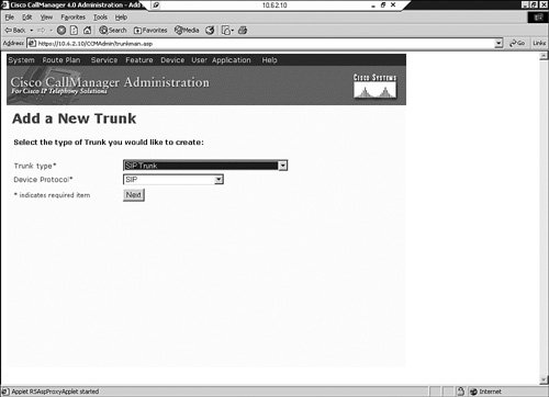
|
|
Step 3. |
The Trunk Configuration screen, shown in Figure 4-7, appears next. Enter the name of the device at the other end of the trunk, and optionally a description. You must select a Device Pool. Then designate whether calls to this trunk are OnNet or OffNet, or let the system decide. Note that a media termination point (MTP) is required. This is to translate DTMF signals between SIP and SCCP phones. For more information, see the later section, "DTMF Relay." Figure 4-7. SIP Trunk Configuration in CallManager 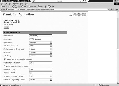
|
|
Step 4. |
On this same screen, enter the destination address of the trunk. |
|
Step 5. |
The next options in the Trunk Configuration screen are for the Destination Port number, the Incoming Port number, and the Outgoing Transport Type (Layer 4 protocol). The default destination port for SIP is 5060, and it is typically left at that. CallManager can have multiple SIP signaling interfaces. You must use a unique incoming port for each signaling interface in CCM 4.x. Not shown in Figure 4-7 are settings for incoming and outgoing calls, further down on the screen. |
|
Step 6. |
When you are finished with the configuration, click Insert. You are then prompted to reset the trunk. |
|
Step 7. |
You can verify your trunk configuration by going back to the Find and List Trunks page. Click the Find button, and verify that your new trunk is there, as shown in Figure 4-8. After you have created the trunk, you can assign route patterns, list, or groups to it as normal. Figure 4-8. Verifying a SIP Trunk in CallManager 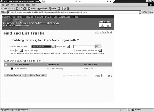
|
Configuring a SIP Trunk with CallManager 5.x
The process that you use to register a SIP trunk with CallManager 5.x is slightly different from the CallManager 4.x process. For instance, an MTP is not required with CallManager 5.x if the endpoints can negotiate using out-of-band DTMF relay. Multiple trunks can have the same incoming port number.
To begin adding a SIP trunk in CCM 5, follow Steps 1 and 2 in the CallManager 4.x process. The next screen, the Trunk Configuration screen, has some different fields, and some fields are in different positions in CallManager 5.x. Figures 4-9, 4-10, and 4-11 show this Trunk Configuration screen. Some items to note are that the MTP might not be required and is not checked automatically. Some SIP-specific fields have been added, such as Presence Group, SIP Trunk Security Profile, SIP Profile, and SUBSCRIBE Calling Search Space.
Figure 4-9. Configuring a SIP Trunk in CCM 5
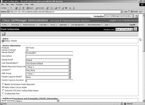
Figure 4-10. Configuring a SIP Trunk in CCM 5 (continued)
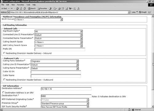
Figure 4-11. Configuring a SIP Trunk in CCM 5 (continued)
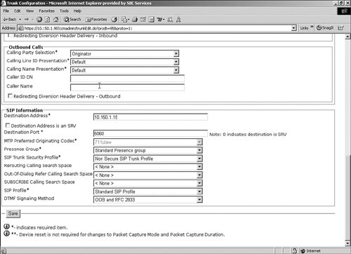
When you are finished configuring the trunk, you must save it by clicking the Save button on the bottom of the screen or the disk icon at the top of the screen. You can verify SIP trunk configuration for CallManager 5.x by using the same method that you used for CallManager 4.xby using the Find button at the Find and List Trunks page.
Configuring the Gateway for a CallManager Trunk
Regardless of the CallManager version you use, the gateway sees it as a SIP dial peer. For redundancy, you can configure a dial peer for each CCM in the cluster, using preference to determine their order of use. Example 4-7 (shown previously) demonstrates the configuration for a basic SIP dial peer.
DTMF Relay
DTMF tones are the tones that are generated when a telephone key is pressed on a touchtone phone. Sometimes the called endpoint needs to hear those tones, such as when you enter digits during the call in response to a menu. Low-bandwidth codecs can distort the sound, however. DTMF relay allows that tone information to be reliably passed from one endpoint to the other. By default, SIP uses in-band signaling, sending the DTMF information in the voice stream. However, you can configure it to use RTP-NTE, SIP INFO messages, SIP NOTIFY messages, or KPML for transmitting DTMF tone information.
RTP-NTE is an in-band DTMF relay method, which uses RTP Named Telephony Event (NTE) packets to carry DTMF information instead of voice. If RTP-NTE is configured, SDP is used to negotiate the payload type value for NTE packets and the events that will be sent using NTE.
RTP-NTE can cause problems communicating with SCCP phones, which use only out-of-band DTMF relay. In a CallManager 4.x network with SCCP phones, you must provision an MTP for calls that traverse the SIP trunk. This MTP translates between in-band and out-of-band DTMF signals. You must configure a separate MTP for each side of the SIP trunk. You can do this MTP in hardware, or in software on CallManager.
Cisco has two out-of-band procedures for DTMF relay. One uses SIP INFO methods, and the other uses SIP NOTIFY methods. The SIP INFO method sends DTMF digits in INFO messages. It is always enabled. When a gateway receives an INFO message containing DTMF relay information, it sends the corresponding tone.
NOTIFY-based out-of-band DTMF relay is negotiated by including a Call-Info field in the SIP INVITE and response messages. This field indicates an ability to use NOTIFY for DTMF tones and the duration of each tone in milliseconds. Using this method can help SIP gateways interoperate with Skinny phones. You can also use it for analog phones that are connected to Foreign Exchange Station (FXS) ports on the gateway.
When a DTMF tone is generated, the gateway sends a NOTIFY message to the terminating gateway. When that gateways receives the NOTIFY, it responds with SIP 200 OK and plays the DTMF tone. To configure the DTMF relay type, use the dtmf-relay command in dial-peer configuration mode. To optionally configure the interval between NOTIFY messages for a single DTMF event, use the notify telephone-event max-duration milliseconds command in SIP UA configuration mode. The default is 2000 msec; the lowest value between two SIP peers is the one chosen.
Example 4-10 shows these commands. Notice that two types of DTMF relay are configured. The router prefers SIP-NOTIFY but uses RTP-NTE if the other side does not support SIP-NOTIFY. If no DTMF relay method is configured, the tones are sent in-band.
!Setting the NOTIFY interval SIP-GW(config)#sip-ua SIP-GW(config-sip-ua)#notify telephone-event max-duration 1000 SIP-GW(config-sip-ua)#exit ! !Setting NOTIFY-based out-of-band DTMF relay SIP-GW(config)#dial-peer voice 3400 voip SIP-GW(config-dial-peer)#dtmf-relay ? cisco-rtp Cisco Proprietary RTP h245-alphanumeric DTMF Relay via H245 Alphanumeric IE h245-signal DTMF Relay via H245 Signal IE rtp-nte RTP Named Telephone Event RFC 2833 sip-notify DTMF Relay via SIP NOTIFY messages SIP-GW(config-dial-peer)#dtmf-relay sip-notify rtp-nte |
KPML is another way for SIP phones to send dialed-digit information, as described previously in the "Dial Plan Considerations" section. Like SIP-NOTIFY, KPML uses a NOTIFY message to transmit each digit.
Part I: Voice Gateways and Gatekeepers
Gateways and Gatekeepers
- Gateways and Gatekeepers
- The Role of Voice Gateways
- The Role of Voice Gatekeepers
- The Role of IP-to-IP Gateways
- Introduction to Voice Protocols
- Call Control Agents
- Deployment Scenarios
- Case Study: Introduction
- Chapter Review Questions
Part II: Gateways
Media Gateway Control Protocol
- Media Gateway Control Protocol
- Introduction to MGCP
- MGCP Operation
- Call Flow with MGCP
- Dial Plan Considerations
- Implementing MGCP Gateways
- Securing MGCP Gateways
- Troubleshooting Tools
- Case Study: Configuring an MGCP Gateway
- Review Questions
H.323
- H.323
- H.323 Specifications
- H.323 Network Components
- Call Flow
- H.323 Protocol Pros and Cons
- When to Use H.323
- Dial Plan Considerations
- Implementing H.323 Gateways
- Securing H.323 Gateways
- Troubleshooting Tools
- Case Study: Configuring an H.323 Gateway
- Review Questions
Session Initiation Protocol
- Session Initiation Protocol
- Description of SIP
- SIP Call Flow
- SIP Pros and Cons
- When to Use SIP
- Dial Plan Considerations
- Implementing SIP Gateways
- Securing SIP Gateways
- Allowing H.323 to SIP Connections
- Troubleshooting Tools
- Case Study: Configuring SIP Between a Gateway and CallManager 5.x
- Review Questions
Circuit Options
Connecting to the PSTN
- Connecting to the PSTN
- PSTN Circuit Selection Overview
- Analog Trunks
- Digital Trunks
- Case Study: Add an E1 R2 Connection to the Leeds Gateway
- Review Questions
Connecting to PBXs
- Connecting to PBXs
- Analog Trunks
- Digital Trunks
- Configuring Transparent Common Channel Signaling
- Case Study: Implementing a Cisco Voice Gateway at the Shanghai Office
- Review Questions
Connecting to an IP WAN
- Connecting to an IP WAN
- Applications for Connecting to an IP WAN
- Design Considerations
- Quality of Service
- Providing Fax and Modem Services
- Security
- Case Study: Using a T1 Link as a Tie Line
- Review Questions
Dial Plans
- Dial Plans
- Numbering Plans
- Overlapping Numbering Plans
- Building a Scalable Dial Plan
- Dial Peers
- Dial Peer Matching
- Case Study: Configuring PSTN Access
- Review Questions
Digit Manipulation
- Digit Manipulation
- Basic Digit Manipulation
- Number Expansion
- Voice Translation Rules and Profiles
- Manipulating Caller ID
- Order of Operation in Digit Manipulation
- Troubleshooting Digit Manipulation
- Case Study
- Review Questions
Influencing Path Selection
- Influencing Path Selection
- Hunt Groups
- Using Trunk Groups
- Tail-End Hop-Off
- Call Admission Control
- POTS-to-POTS Call Routing Considerations
- Case Study: Implementing Gateway-Controlled RSVP
- Review Questions
Configuring Class of Restrictions
- Configuring Class of Restrictions
- COR Overview
- COR Operation
- Implementing COR
- Assigning COR Lists with SRST
- Assigning COR Lists with Cisco CallManager Express
- Restricting Inbound Calls
- Case Study: Implementing COR for Miami
- Review Questions
SRST and MGCP Gateway Fallback
- SRST and MGCP Gateway Fallback
- SRST Overview
- Configuring SRST
- Dial Plan Considerations
- SRST Features
- SIP SRST
- Call Preservation
- Secure SRST
- MGCP Gateway Fallback
- Configuring MGCP Gateway Fallback
- Verifying and Troubleshooting SRST
- Verifying and Troubleshooting MGCP Gateway Fallback
- Case Study: Integrating SRST with an Analog Voice-Mail System
- Review Questions
DSP Resources
- DSP Resources
- Need for DSP Resources
- Determining the DSP Resources Required
- Configuring DSP Resources
- Transcoding for CallManager Express
- Case Study: Add DSP Resources to the Miami Gateway
- Review Questions
Using Tcl Scripts and VoiceXML
- Using Tcl Scripts and VoiceXML
- Tcl IVR and VoiceXML Application Overview
- Sample Applications
- Downloading Tcl Scripts from Cisco.com
- Configuring the Gateway to Use a Tcl Script
- Implementing the AA Tcl Script
- Creating Audio Files
- Restrictions and Caveats
- Case Study: Implementing ACD Application
- Review Questions
Part III: Gatekeepers
Deploying Gatekeepers
- Deploying Gatekeepers
- Gatekeeper Functionality
- Gatekeeper Signaling
- E.164 Number Resolution
- Call Admission Control
- Gatekeeper Deployment Models
- Gatekeepers with CallManager
- Security with Gatekeepers
- Review Questions
Gatekeeper Configuration
- Gatekeeper Configuration
- Configuring Basic Gatekeeper Functionality
- Multiple Gatekeeper Configurations
- Configuring Directory Gatekeepers
- Troubleshooting Gatekeepers
- CallManager and Gatekeepers
- Gatekeeper Redundancy
- Configuring Resource Availability Indicator
- Configuring Gatekeeper Security
- Case Study: Deploying Gatekeepers to Assist in Migration to VoIP
- Review Questions
Part IV: IP-to-IP Gateways
Cisco Multiservice IP-to-IP Gateway
- Cisco Multiservice IP-to-IP Gateway
- IP-to-IP Gateway Overview
- Cisco Multiservice IP-to-IP Gateway
- Basic Configuration
- IP-to-IP Gateway Features
- Case Study: Providing Enterprise VoIP Trunking to VoIP Service of the Service Provider
- Review Questions
Appendix A. Answers to Chapter-Ending Review Questions
Index
EAN: 2147483647
Pages: 218
