A QUADRATURE OSCILLATOR
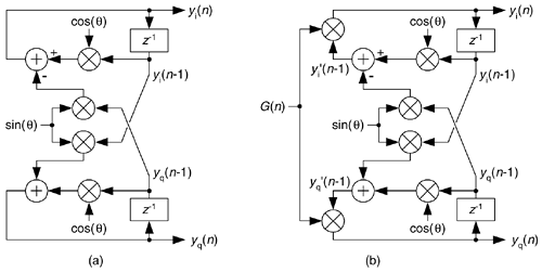
Here we present a well-behaved digital quadrature oscillator, whose output is yi(n) + jyq(n), having the structure shown in Figure 13-79(a). If you're new to digital oscillators, that structure looks a little complicated but it's really not so bad. If you look carefully, you see the computations are

Figure 13-79. Quadrature oscillators: (a) standard structure; (b) structure with AGC.

and
Equation 13-134'

Those computations are merely the rectangular form of multiplying the previous complex output by a complex exponential ejq as
Equation 13-135

So the theory of operation is simple. Each new complex output sample is the previous output sample rotated by q radians, where q is 2pft/fs with ft and fs being the oscillator tuning frequency and the sample rate, respectively, in Hz.
To start the oscillator, we set the initial conditions of yi(n–1) = 1 and yq(n–1) = 0 and repeatedly compute new outputs, as time index n advances, using Eq. (13-134). This oscillator is called a coupled quadrature oscillator because the both of its previous outputs are used to compute each new in-phase and each new quadrature output. It's a useful oscillator because the full range of tuning frequencies are available (from nearly zero Hz up to roughly fs/2), and its outputs are equal in amplitude unlike some other quadrature oscillator structures[77]. The tough part, however, is making this oscillator stable in fixed-point arithmetic implementations.
Depending on the binary word widths, and the value q, the output amplitudes can either grow or decay as time increases because it's not possible to represent ejq having a magnitude of exactly one, over the full range of q, using fixed-point number formats. The solution to amplitude variations is to compute  and
and  and multiply those samples by an instantaneous gain factor G(n) as shown in Figure 13-79(b). The trick here is how to compute the gain samples G(n).
We can use a linear automatic gain control (AGC) method, described in Section 13-30, as shown in Figure 13-80(a) where a is a small value, say, a = 0.01. The value R is the desired rms value of the oscillator outputs. This AGC method greatly enhances the stability of our oscillator. However, there's a computationally simpler AGC scheme for our oscillator that can be developed using the Taylor series approximation we learned in school. Here's how.
Figure 13-80. AGC schemes: (a) linear AGC; (b) simplified AGC.

Using an approach similar to Reference [78], we can define the desired gain as
Equation 13-136

This is the desired output signal magnitude Mdes over the actual output magnitude Mact. We can also represent the gain using power as
Equation 13-137

where the constant Pdes is the desired output signal power and Pact is the actual output power. The right side of Eq. (13-137) shows Pact replaced by the desired power Pdes plus an error component E, and that's the ratio we'll compute. To avoid square root computations and, because the error E will be small, we'll approximate that ratio with a two-term Taylor series expansion about E = 0 using
Equation 13-138

Computing the Taylor series' coefficients to be a0 = 1 and a1 = –1/2Pdes, and recalling that E = Pact–Pdes, we estimate the instantaneous gain as
Equation 13-139

If we let the quadrature output peak amplitudes equal 1/  , Pdes equals 1/2 and we eliminate the division in Eq. (13-139) obtaining
Equation 13-140

The simplified structure of the G(n) computation is shown in Figure 13-80(b).
As for practical issues, to avoid gain values greater than one (for those fixed-point fractional number systems that don't allow numbers  1), we use the clever recommendation from Reference [77] of multiplying by G(n)/2 and doubling the products in Figure 13-79(b). Reference [78] recommends using rounding, instead of truncation, for all intermediate computations to improve output spectral purity. Rounding also provides a slight improvement in tuning frequency control. Because this oscillator is guaranteed stable, and can be dynamically tuned, it's definitely worth considering for real-valued as well as quadrature oscillator applications[77].
URL http://proquest.safaribooksonline.com/0131089897/ch13lev1sec32
 |
Amazon |  |
