A/D CONVERTER TESTING TECHNIQUES
A D CONVERTER TESTING TECHNIQUES
We can take advantage of digital signal processing techniques to facilitate the testing of A/D converters. In this section we present two schemes for measuring converter performance; first, a technique using the FFT to estimate overall converter noise, and second, a histogram analysis scheme to detect missing converter output codes.
13.9.1 Estimating A/D Quantization Noise with the FFT
The combination A/D converter quantization noise, missing bits, harmonic distortion, and other nonlinearities can be characterized by analyzing the spectral content of the converter's output. Converter performance degradation caused by these nonlinearities is not difficult to recognize because they show up as spurious spectral components and increased background noise levels in the A/D converter's output samples. The traditional test method involves applying a sinusoidal analog voltage to an A/D converter's input and examining the spectrum of the converter's digitized time-domain output samples. We can use the FFT to compute the spectrum of an A/D converter's output samples, but we have to minimize FFT spectral leakage to improve the sensitivity of our spectral measurements. Traditional time-domain windowing, however, provides insufficient FFT leakage reduction for high-performance A/D converter testing.
The trick to circumventing this FFT leakage problem is to use an sinusoidal analog input voltage whose frequency is an integer fraction of the A/D converter's clock frequency as shown in Figure 13-22(a). That frequency is mfs/N, where m is an integer, fs is the clock frequency (sample rate), and N is the FFT size. Figure 13-22(a) shows the x(n) time domain output of an ideal A/D converter when its analog input is a sinewave having exactly eight cycles over N = 128 converter output samples. In this case, the input frequency normalized to the sample rate fs is 8fs/128 Hz. Recall from Chapter 3 that the expression mfs/N defined the analysis frequencies, or bin centers, of the DFT, and a DFT input sinusoid whose frequency is at a bin center causes no spectral leakage.
Figure 13-22. Ideal A/D converter output when the input is an analog 8fs/128 Hz sinusoid: (a) output time samples; (b) spectral magnitude in dB.
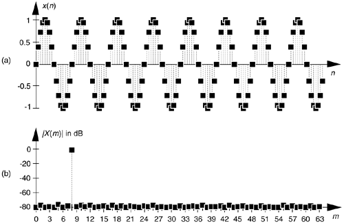
The first half of a 128-point FFT of x(n) is shown in the logarithmic plot in Figure 13-22(b) where the input tone lies exactly at the m = 8 bin center and FFT leakage has been sufficiently reduced. Specifically, if the sample rate were 1 MHz, then the A/D's input analog tone would have to be exactly 8(106/128) = 62.5 kHz. In order to implement this scheme we need to ensure that the analog test generator be synchronized, exactly, with the A/D converter's clock frequency of fs Hz. Achieving this synchronization is why this A/D converter testing procedure is referred to as coherent sampling[24–26]. That is, the analog signal generator and the A/D clock generator providing fs must not drift in frequency relative to each other—they must remain coherent. (We must take care here from a semantic viewpoint because the quadrature sampling schemes described in Chapter 8 are also sometimes called coherent sampling, and they are unrelated to this A/D converter testing procedure.)
As it turns out, some values of m are more advantageous than others. Notice in Figure 13-22(a), that when m = 8, only nine different amplitude values are output by the A/D converter. Those values are repeated over and over. As shown in Figure 13-23, when m = 7 we exercise many more than nine different A/D output values.
Figure 13-23. Seven-cycle sinusoidal A/D converter output.
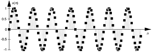
Because it's best to test as many A/D output binary words as possible, while keeping the quantization noise sufficiently random, users of this A/D testing scheme have discovered another trick. They found that making m an odd prime number (3, 5, 7, 11, etc.) minimizes the number of redundant A/D output word values.
Figure 13-24(a) illustrates an extreme example of nonlinear A/D converter operation, with several discrete output samples having dropped bits in the time domain x(n) with m = 8. The FFT of this distorted x(n) is provided in Figure 13-24(b) where we can see the increased background noise level due to the A/D converter's nonlinearities compared to Figure 13-22(b).
Figure 13-24. Non-ideal A/D converter output showing several dropped bits: (a) time samples; (b) spectral magnitude in dB.
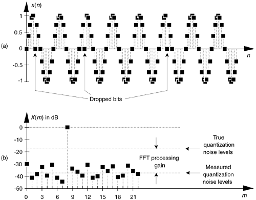
The true A/D converter quantization noise levels will be higher than those measured in Figure 13-24(b). That's because the inherent processing gain of the FFT (discussed in Section 3.12.1) will pull the high-level m = 8 spectral component up out of the background quantization noise. Consequently, if we use this A/D converter test technique, we must account for the FFT's processing gain of 10log10(N/2) as indicated in Figure 13-24(b).
To fully characterize the dynamic performance of an A/D converter we'd need to perform this testing technique at many different input frequencies and amplitudes.[ ] The key issue here is that when any input frequency is mfs/N, where m is less than N/2 to satisfy the Nyquist sampling criterion, we can take full advantage of the FFT's processing capability while minimizing spectral leakage.
[
] The analog sinewave applied to an A/D converter must, of course, be as pure as possible. Any distortion inherent in the analog signal will show up in the final FFT output and could be mistaken for A/D nonlinearity.
In closing, applying the sum of two analog tones to an A/D converter's input is often done to quantify the intermodulation distortion performance of a converter, which in turn characterizes the converter's dynamic range. In doing so, both input tones must comply with the mfs/N restriction. Figure 13-25 shows the test configuration. It's prudent to use bandpass filters (BPF) to improve the spectral purity of the sinewave generators' outputs, and small-valued fixed attenuators (pads) are used to keep the generators from adversely interacting with each other. (I recommend 3-dB attenuators for this.) The power combiner is typically an analog power splitter driven backward, and the A/D clock generator output is a squarewave. The dashed lines in Figure 13-25 indicate that all three generators are locked to the same frequency reference source.
Figure 13-25. A/D converter hardware test configuration.

13.9.2 Detecting Missing Codes
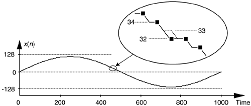
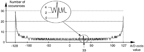
One problem that can plague A/D converters is missing codes. This defect occurs when a converter is incapable of outputting a specific binary word (a code). Think about driving an 8-bit converter with an analog sinusoid and the effect when its output should be the binary word 00100001 (decimal 33); its output is actually the word 00100000 (decimal 32) as shown in Figure 13-26. The binary word representing decimal 33 is a missing code. This subtle nonlinearity is very difficult to detect by examining time-domain samples or performing spectrum analysis. Fortunately there is a simple, reliable way to detect the missing 33 using histogram analysis.
Figure 13-26. Time-domain plot of an 8-bit converter exhibiting a missing code of binary value 0010001, decimal 33.
The histogram testing technique merely involves collecting many A/D converter output samples and plotting the number of occurrences of each sample value versus that sample value as shown in Figure 13-27. Any missing code (like our missing 33) would show up in the histogram as a zero value. That is, there were zero occurrences of the binary code representing a decimal 33.
Figure 13-27. An 8-bit converter's histogram plot of the number of occurrences of binary words (codes) versus each word's decimal value.
 |
Amazon |  |
