IMPROVING TRADITIONAL CIC FILTERS
A major design goal for cascaded integrator-comb (CIC) filters, as introduced in Section 10.5 in conjunction with sample rate conversion, is to minimize their hardware power consumption by reducing data word width and reducing data clock rates wherever possible. Here we introduce a clever trick that reduces CIC filter power consumption using nonrecursive structures, by means of polynomial factoring, easing the word width growth problem. These nonrecursive structures require that the sample rate change R be an integer power of two enhancing computational simplicity through polyphase decomposition, transposed structures, simplified multiplication, and substructure sharing[61–63]. (These processes are not complicated; they merely have fancy names.) Next, we'll review a nonrecursive scheme that enables sample rate changes other than powers of two. The following discussion assumes that the reader is familiar with the CIC filter material in Section 10.5.
13.24.1 Nonrecursive CIC Filters
Recall that the structures of first-order (M = 1) and third-order (M = 3) CIC decimation filters, having a comb delay equal to the sample rate change factor R, are those shown in Figure 13-66. As presented in Section 10.5, the transfer function of an Mth-order decimating CIC filter can be expressed either in a recursive form or a nonrecursive form, as indicated in Eq. (13-119). (You could, if you wish, use the geometric series discussion in Appendix B to show the equality of the two forms of the filter's transfer function.)

Equation 13-119'

Figure 13-66. Recursive decimation CIC filters: (a) first-order filter; (b) third-order filter.

Now if the sample rate change factor R is an integer power of two, R = 2K where K is some positive integer, the Eq. (13-119') Mth-order nonrecursive polynomial form of Hcic(z) can be factored as
Equation 13-120

The reward for this factorization is that the CIC filter can then be implemented with K nonrecursive stages as shown in Figure 13-67. This implementation eliminates filter feedback loops with their unpleasant binary word width growth. The data word width does increase in this nonrecursive structure by M bits for each stage, but the sampling rate is reduced by a factor of two for each stage. This nonrecursive structure has been shown to consume less power than the Figure 13-66(b) recursive implementation for filter orders greater than three and decimation/interpolation factors larger than eight[63]. Thus the power savings from sample rate reduction is greater than the power consumption increase due to data word width growth.
Figure 13-67. Multistage Mth-order nonrecursive CIC structure.

Happily, further improvements are possible with each stage of this nonrecursive structure[62]. For example, assume we desire an M = fifth-order decimating CIC for Stage 1 in Figure 13-67. In that case, the stage's transfer function is
Equation 13-121

The second step in Eq. (13-121), known as polyphase decomposition[64–68], enables a polyphase implementation having two parallel paths as shown in Figure 13-68. The decimation by two is implemented by routing the odd-index input samples to FA'(z), and the even-index samples to FB'(z). Because we implement decimation by 2 before the filtering, the new polyphase components are FA'(z) = 1 + 10z–1 + 5z–2, and FB'(z) = 5 + 10z–1 + z–2 implemented at half the data rate into the stage. (Reducing data rates as early as possible is a key design goal in the implementation of CIC decimation filters.)
Figure 13-68. Polyphase structure of a single nonrecursive fifth-order CIC stage.

The FA'(z) and FB'(z) polyphase components are implemented in a tapped-delay line fashion and, fortunately, further simplifications are possible. Let's consider the FA'(z) polyphase filter component, in a tapped-delay line configuration, shown in Figure 13-69(a). The transposed version of this filter is presented in Figure 13-69(b) with its flipped coefficient sequence. The adder in the Figure 13-69(a) must perform two additions per input data sample, while in the transposed structure no adder need perform more than one add per data sample. Thus the transposed structure can operate at a higher speed.
Figure 13-69. Filter component FA'(z): (a) delay line structure; (b) transposed structure; (c) simplified multiplication; (d) substructure sharing.

The next improvement uses simplified multiplication, as shown in Figure 13-69(c), by means of arithmetic shifts and adds. Thus a factor of 5 is implemented as 22 + 1, eliminating all multiplications. Finally, because of the transposed structure, we can use the technique of substructure sharing in Figure 13-69(d) to reduce the hardware component count. Pretty slick! By the way, these nonrecursive filters are still called cascaded integrator-comb filters, even though they have no integrators. Go figure.
Table 13-7 is provided to help the reader avoid computing the polynomial equivalent of several Mth-order nonrecursive stages, as was performed in Eq. (13-121).
13.24.2 Nonrecursive Prime Factor-R CIC Filters
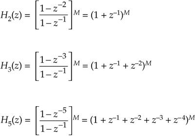
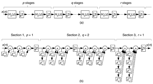
The nonrecursive CIC decimation filters described above have the restriction that the R decimation factor must be an integer power of two. That constraint is loosened due to a clever scheme of factoring R into a product of prime numbers[69]. This multiple prime-factor-R technique is based on the process of factoring integer R into the form R = 2p3q5r7s11t ..., where 2, 3, 5, 7, 11 are the prime numbers. (This process is called prime factorization, or prime decomposition, and has been of interest since the days of Euclid.). Then the appropriate number of CIC subfilters are cascaded as shown in Figure 13-70(a). The fortunate condition is that those Mth-order CIC filters are described by
Equation 13-122

Figure 13-70. Multiple prime-factor nonrecursive CIC example: (a) cascaded-stage structure; (b) third-order, R = 90, nonrecursive CIC example.

Table 13-7. Expansions of (1 + z–1)M.
|
M |
(1 + z–1)M |
|---|---|
|
2 |
(1 + z–1)2 = 1 + 2z–1 + z–2 |
|
3 |
(1 + z–1)3 = 1 + 3z–1 + 3z–2 + z–3 |
|
4 |
(1 + z–1)4 = 1 + 4z–1 + 6z–2 + 4z–3 + z–4 |
|
5 |
(1 + z–1)5 = 1 + 5z–1 + 10z–2 + 10z–3 + 5z–4 + z–5 |
|
6 |
(1 + z–1)6 = 1 + 6z–1 + 15z–2 + 20z–3 + 15z–4 + 6z–5 + z–6 |
|
7 |
(1 + z–1)7 = 1 + 7z–1 + 21z–2 + 35z–3 + 35z–4 + 21z–5 + 7z–6 + z–7 |
|
8 |
(1 + z–1)8 = 1 + 8z–1 + 28z–2 + 56z–3 + 70z–4 + 56z–5 + 28z–6 + 8z–7 + z–8 |
|
9 |
(1 + z–1)9 = 1 + 9z–1 + 36z–2 + 84z–3 + 126z–4 + 126z–5 + 84z–6 + 36z–7 + 9z–8 + z–9 |
and so on, enabling nonrecursive implementations.
Due to space constraints, the elegant and arduous derivation of this technique is not given here; but this process can illustrated with an example. Assume we desire a third-order CIC filter with a decimation factor of R = 90. That decimation rate is factored as 90 = (2)(3)(3)(5). So p = 1, q = 2, and r = 1. Our composite CIC filter is implemented as H2(z)H3(z)H3(z)H5(z) shown in Figure 13-70(b).
At first glance the many additions of the Figure 13-70(b) CIC filter appear to aggravate the power consumption of such a filter, but the reduced sample rates significantly reduce power requirements[69]. If one addition in Section 1 of Figure 13-70(b) consumes P units of power, then Section 1 consumes 3P units of power, and each addition in the first portion of Section 2 consumes P/2 units of power. Each addition in the second portion of Section 2 consumes P/6 of units power, while each addition in Section 3 consumes P/18 units of power.
We have flexibility here because the subfilters in each section of Figure 13-70(b) can be implemented recursively or nonrecursively, as indicated in Eq. (13-122). In nonrecursive implementations the polyphase decomposition, transposed structures, simplified multiplication, and substructure sharing schemes can be applied. CIC filter design certainly has come a long way since its introduction in the early 1980s.
URL http://proquest.safaribooksonline.com/0131089897/ch13lev1sec24
 |
Amazon |  |
