Setting Up RSVP-Signaled LSPs
Problem
You want to use RSVP as the signaling protocol so you can implement some of the traffic engineering features available only with RSVP, including protecting traffic links.
Solution
For each MPLS LSP, configure the ingress, transit, and egress routers on the path. On the ingress router, first configure the interface to support MPLS addressing:
	[edit interfaces]
	aviva@R1# set so-0/0/2 unit 0 family mpls
Then enable the MPLS protocol on the interface:
	[edit protocols]
	aviva@R1# set mpls interface so-0/0/2
	aviva@R1# set mpls interface fxp0.0 disable
Finally, turn on RSVP as the signaling protocol:
	[edit protocols]
	aviva@R1# set rsvp interface so-0/0/2
On the transit and egress routers, turn on MPLS and RSVP in a similar fashion. R6 is the egress router:
	[edit interfaces]
	aviva@R6# set so-0/0/3 unit 0 family mpls

	[edit protocols]
	aviva@R6# set mpls interface so-0/0/3
	aviva@R6# set mpls interface fxp0.0 disable
	aviva@R6# set rsvp interface so-0/0/3
	aviva@R6# set rsvp interface fxp0.0 disable
R3 is the transit router:
	[edit interfaces]
	aviva@R3# set so-0/0/2 unit 0 family mpls
	aviva@R3# set so-0/0/3 unit 0 family mpls

	[edit protocols]
	aviva@R3# set mpls interface so-0/0/2
	aviva@R3# set mpls interface so-0/0/3
	aviva@R3# set mpls interface fxp0.0 disable
	aviva@R3# set rsvp interface so-0/0/2
	aviva@R3# set rsvp interface so-0/0/3
	aviva@R3# set
rsvp interface fxp0.0 disable
Then, on the ingress router, set up the LSP:
	[edit protocols
mpls]
	aviva@R1# set mpls
label-switched-path R1-to-R6 to 10.0.0.6
Also set up a return LSP from R6 to R1 so that the LSP is bidirectional and traffic can travel from the egress router back to the ingress router:
	[edit protocols]
	aviva@R6# set mpls label-switched-path R6-to-R1 to 10.0.0.1
Discussion
This recipe shows how to use RSVP as the signaling protocol for MPLS, based on the topology shown in Figure 14-6. Interfaces running MPLS must also be running BGP and an IGP (either IS-IS or OSPF). In this topology, all interfaces are running IS-IS and OSPF.
Figure 14-6. MPLS with RSVP topology
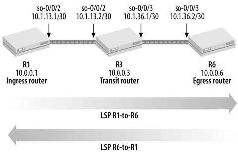
As with the LDP configuration, first configure the MPLS address family on the logical interfaces so the interface can process labeled packets. On the ingress router, R1, set the MPLS family on the so-0/0/2 interface. On the transit router, R3, add it to the so-0/0/2 and so-0/0/3 interfaces. On the egress router, R6, configure it on the so-0/0/3 interface. The configuration for each physical interface now has three families, IPv4 (inet), iso (for IS-IS), and MPLS:
	aviva@R1> show configuration interfaces
	so-0/0/2 {
	 unit 0 {
	 family inet {
	 address 10.1.13.1/30;
	 }
	 family iso;
	 family mpls;
	 }
	}
	fxp0 {
	 unit 0 {
	 family inet {
	 address 192.168.70.143/21;
	 }
	 }
	}
	lo0 {
	 unit 0 {
	 family inet {
	 address 10.0.0.1/32;
	 }
	 family iso {
	 address 49.0004.1000.0000.0001.00;
	 }
	 }
	}
You see that on physical interface so-0/0/2 on the ingress router, the MPLS family is configured in addition to the inet and iso families. You don configure the MPLS family on either the loopback (lo0) or fxp0 interfaces because they are not transit interfaces and never carry labeled packets.
Use the show interfaces terse command to verify that the MPLS family is configured on all expected interfaces. Heres the output for the ingress router:
	aviva@R1> show interfaces terse
	Interface Admin Link Proto Local Remote
	so-0/0/2 up up
	so-0/0/2.0 up up inet 10.1.13.1/30
	 iso
	 mpls
	fxp0 up up
	fxp0.0 up up inet 192.168.70.143/21
	lo0 up up
	lo0.0 up up inet 10.0.0.1 --> 0/0
	 iso 49.0004.1000.0000.0001.00
	lo0.16385 up up inet
	 inet6 fe80::2a0:a5ff:fe56:189
Heres the output for the transit router:
	aviva@R3> show interfaces terse
	Interface Admin Link Proto Local Remote
	so-0/0/2 up up
	so-0/0/2.0 up up inet 10.1.13.2/30
	 iso
	 mpls
	so-0/0/3 up up
	so-0/0/3.0 up up inet 10.1.36.1/30
	 iso
	 mpls
	fxp0 up up
	fxp0.0 up up
inet 192.168.70.145/21
	lo0 up up
	lo0.0 up up inet 10.0.0.3 --> 0/0
	 iso 49.0002.1000.0000.0003.00
	lo0.16385 up up inet
	 inet6 fe80::2a0:a5ff:fe56:416
On both routers, you see that the MPLS family is enabled on the appropriate logical interfaces (so-0/0/2 on the ingress router, and so-0/0/2 and so-0/0/3 on the transit router). You also see that the inet and iso families are configured on these interfaces and on the routers lo0 interfaces.
Next, configure the three routers that will form the LSP to run MPLS. The basic configuration is very simple. In the [edit protocols mpls] section of the configuration hierarchy, list the router interfaces on which MPLS will run. For the ingress router, configure MPLS on the interface that leads toward the transit router in the LSP and disable MPLS on the routers fxp0 interface:
	aviva@R1> show configuration protocols mpls
	interface so-0/0/2.0;
	interface fxp0.0 {
	 disable;
	}
The SONET interface so-0/0/2 connects from the ingress router to the transit router. This lab setup uses M7i routers, so we disable MPLS on the fxp0 interface, which, while not required, is considered to be good practice.
After configuring the MPLS interfaces, check that MPLS is running on the interfaces. Heres the status on the ingress router:
	aviva@R1>
show mpls interface
	Interface State Administrative groups
	so-0/0/2.0 Up
The output shows that MPLS is up and running on interface so-0/0/2. Also, confirm MPLS status on the transit and egress routers:
aviva@R3> show mpls interface Interface State Administrative groups so-0/0/2.0 Upso-0/0/3.0 Up aviva@R6> show mpls interface Interface State Administrative groups so-0/0/3.0 Up
You see that all required MPLS interfaces are up and running.
The next step in the configuration is to set up RSVP as the signaling protocol. The basic configuration is similar to that for MPLS: you list all router interfaces that will be running RSVP. These are the same interfaces that you configured for MPLS. Use the set rsvp interface command to configure these interfaces in the [edit protocols] hierarchy. As with MPLS, do not include the lo0 and fxp0 interfaces in the list of RSVP interfaces because they do not carry labeled traffic. Also, as with MPLS, it is considered good practice to disable RSVP on the fxp0 interface. Use the following command to verify the configuration:
	aviva@R1> show configuration protocols rsvp
	interface so-0/0/2.0;
	interface fxp0.0 {
	 disable;
	}
The show rsvp version command shows you whether RSVP is running on the router:
	aviva@R1> show rsvp version
	Resource ReSerVation Protocol, version 1. rfc2205
	 RSVP protocol = Enabled
	 R(refresh timer) = 30 seconds
	 K(keep multiplier) = 3

Preemption = Normal

Soft-preemption cleanup = 30 seconds
	 Graceful deletion timeout = 30 seconds
	 Graceful restart = Disabled
	 Restart helper mode = Enabled
	 Maximum helper restart time = 20000 msec
	 Maximum helper recovery time = 180000 msec
	 Restart time = 0 msec
The first line of the output shows that the JUNOS software is running RSVP Version 1 (defined in RFC 2205). The second line shows that RSVP is enabled on the router. The remaining lines show the settings for various RSVP parameters, which are the default values because we haven configured anything other than basic RSVP functionality at this point. The refresh timer of 30 seconds determines how often RSVP sends periodic messages to its neighbors. The JUNOS software multiplies this value by 1.5 and sends RSVP messages every 45 seconds by default. The keep multiplier indicates the number of RSVP messages that can be lost on a connection before the software considers an RSVP state to be stale.
The fifth line, Preemption, shows the default session preemption type of Normal. RSVP uses preemption to accommodate additional sessions when a link does not have sufficient bandwidth to carry all sessions. Normal preemption means that only new better-priority RSVP sessions can preempt existing ones. (Recipe 14.14 explains how to modify the default preemption behavior.) Normally, sessions are torn down immediately when they are preempted. However, if soft preemption is configured, RSVP attempts for 30 seconds to establish a new session before tearing down the existing one. This is called soft-preemption cleanup. As part of tearing down an LSP, by default, RSVP waits 30 seconds to gracefully time out the session. The last five lines apply to graceful restart, which is disabled on the router.
Next, check that RSVP is up and running on the routers interfaces. Heres the output for the ingress router:
	aviva@R1> show
rsvp interface
	RSVP interface: 1 active
	 Active Subscr- Static Available Reserved Highwater
	Interface State resv iption BW BW BW mark
	so-0/0/2.0 Up 0 100%	 155.52Mbps 155.52Mbps 0bps 0bps
The second column, State, shows that RSVP is running on the so-0/0/2 interface.
Finally, you are ready to configure the LSP between R1 and R6 with the following command. On the ingress router, R1, verify the configuration:
	[edit protocols mpls]
	aviva@R1# set
label-switched-path R1-to-R6 to 10.0.0.6
Then check that the LSP is up:
	aviva@R1> show mpls lsp
	Ingress LSP: 1 sessions
	To From State Rt ActivePath P LSPname
	10.0.0.6 10.0.0.1 Up 1 * R1-to-R6
	Total 1 displayed, Up 1, Down 0

	Egress LSP: 0 sessions
	Total 0 displayed, Up 0, Down 0

	Transit LSP: 0 sessions
	Total 0 displayed, Up 0, Down 0
The output shows one LSP, R1-to-R6, configured on R1 and that this is an ingress LSP. To verify that the LSP is up on all the routers, use the same command to check LSP status. Heres the command output on the transit router:
	aviva@R3> show mpls lsp
	Ingress LSP: 0 sessions
	Total 0 displayed, Up 0, Down 0

	Egress LSP: 0 sessions
	Total 0 displayed, Up 0, Down 0

	Transit LSP: 1 sessions
	To From State Rt Style Labelin Labelout LSPname
	10.0.0.6 10.0.0.1 Up 1 1 FF 103488 3 R1-to-R6
	Total 1 displayed, Up 1, Down 0
You see that it has one transit LSP from the ingress, 10.0.0.1, to the expected egress at 10.0.0.6. This is LSP R1-to-R6, which is the one we expect. Heres the output on the egress router:
	aviva@R6> show mpls lsp
	Ingress LSP: 0 sessions
	Total 0 displayed, Up 0, Down 0

	Egress LSP: 1 sessions
	To From State Rt Style Labelin Labelout LSPname
	10.0.0.6 10.0.0.1 Up 0 1 FF 3 - R1-to-R6
	Total 1 displayed, Up 1, Down 0
	Transit LSP: 0 sessions
	Total 0 displayed, Up 0, Down 0
This output correctly shows the one LSP we have configured.
For the three routers in the LSP, the show mpls lsp output differs slightly. The P column for R1, the ingress router, contains an asterisk to indicate that LSP R1-to-R6 is the primary LSP between the two routers. The output on the transit and egress routers shows information about the RSVP reservation style and label values.
The command output for the transit router shows that received packets have a label value of 103488 and it uses a label value of 3 on the record for outgoing packets. A label value of 3 is one of the reserved values, used to request that the downstream router pop the label. The transit router is the penultimate-hop router, and the egress router has advertised a label value of 3 to R3 so that it performs penultimate-hop popping to remove the top label on the stack before forwarding packets to R6.
The Rt column in the output on all three routers shows the number of active prefixes installed in the routing table as a result of the RSVP session. Recipe 14.7 explains how to view these routes.
The extensive version of the show mpls lsp command provides additional information about the LSP, including a log of the LSPs history:
	aviva@R1> show mpls lsp extensive
	Ingress LSP: 1 sessions
	10.0.0.6
	 From: 10.0.0.1, State: Up, ActiveRoute: 1, LSPname: R1-to-R6
	 ActivePath: (primary)
	 LoadBalance: Random
	 Encoding type: Packet, Switching type: Packet, GPID: IPv4
	 *Primary State: Up
	 Computed ERO (S [L] denotes strict [loose] hops): (CSPF metric: 20)
	 10.1.13.2 S 10.1.36.2 S
	 Received RRO (ProtectionFlag 1=Available 2=InUse 4=B/W 8=Node 10=SoftPreempt):
	 10.1.13.2 10.1.36.2
	 5 Oct 4 13:31:06 Selected as active path
	 4 Oct 4 13:31:06 Record Route: 10.1.13.2 10.1.36.2
	 3 Oct 4 13:31:06 Up
	 2 Oct 4 13:31:06 Originate Call
	 1 Oct 4 13:31:06 CSPF: computation result accepted
	 Created: Tue Oct 4 13:31:05 2005
	Total 1 displayed, Up 1, Down 0
This command works only on the ingress router because this router is responsible for establishing and maintaining the LSP. The transit and egress routers have no details about the LSPs state. The first line of the output confirms what we already know about the LSP: that it is named R1-to-R6, runs from 10.0.0.1 to 10.0.0.6, and is up. The highlighted lines show the history of the LSP, from most current to oldest events. The last line in the log tells you that the LSP was created at 13:31:05. RSVP used CSPF to determine a path for the LSP (this is the default JUNOS RSVP behavior), and by 13:31:06 the LSP was up and running and was selected as the active path. Consult the LSPs log to help determine the causes of MPLS errors in the network.
You may be wondering why RSVP is using CSPF when setting up the LSP when we haven included anything about turning on CSPF in the configuration. By default, JUNOS RSVP uses CSPF to calculate paths. The data that RSVP uses for the CSPF calculation comes from an IGP, either IS-IS or OSPF. Extensions to both protocols allow them to collect information about the network topology and available bandwidth on network links. The JUNOS implementations of both IGPs support the extensions. This network data for CSPF is stored in a TED on each router. In the JUNOS IS-IS software, these extensions are on by default. Because IS-IS is running as one of the IGPs in our network, it automatically carries the traffic-engineering information. Heres how you can disable the IS-IS support for TE:
	[edit protocols isis]
	aviva@R1# set traffic-engineering disable
In the JUNOS OSPF, the extensions are off by default. You must explicitly configure OSPF support of the CSPF computation:
	[edit protocols ospf]
	aviva@R1# set traffic-engineering
Use the following command to see what information IS-IS and OSPF have added to the TED database:
	aviva@R1> show ted database
	TED database: 3 ISIS nodes 3 INET nodes
	ID Type Age(s) LnkIn LnkOut Protocol
	R1.00(10.0.0.1) Rtr 239 1 1 IS-IS(2)
	 To: R3.00(10.0.0.3), Local: 10.1.13.1, Remote: 10.1.13.2
	ID Type Age(s) LnkIn LnkOut Protocol
	 OSPF(0.0.0.0)
	 To: R3.00(10.0.0.3), Local: 10.1.13.1, Remote: 10.1.13.2
	ID Type Age(s) LnkIn LnkOut Protocol
	R3.00(10.0.0.3) Rtr 468 2 2 IS-IS(2)
	 To: R1.00(10.0.0.1), Local: 10.1.13.2, Remote: 10.1.13.1
	 To: R6.00(10.0.0.6), Local: 10.1.36.1, Remote: 10.1.36.2
	ID Type Age(s) LnkIn LnkOut Protocol
	R6.00(10.0.0.6) Rtr 431 1 1 IS-IS(2)
	 To: R3.00(10.0.0.3), Local: 10.1.36.2, Remote: 10.1.36.1
This output shows three entries and that both IS-IS and OSPF are contributing to the TED database (listed in the Protocol column). All three entries were learned from routers (shown in the Type column). You see that R1 (the ingress router) has one link in and one link out, R2 (the transit router) has two links in either direction, and R3 (the egress router) has one link in and one out, which matches the LSP. The To: lines show the router IDs that correspond to the three routers in the LSP.
The extensive version of this command shows additional information about reservable and available bandwidth on networks links that IS-IS and OSPF have collected for use by CSPF:
aviva@R1> show ted database 10.0.0.1 extensive TED database: 3 ISIS nodes 3 INET nodes NodeID: R1.00(10.0.0.1) Type: Rtr, Age: 621 secs, LinkIn: 1, LinkOut: 1 Protocol: IS-IS(2) To: R3.00(10.0.0.3), Local: 10.1.13.1, Remote: 10.1.13.2 Color: 0Metric: 10 Static BW: 155.52Mbps Reservable BW: 155.52Mbps Available BW [priority] bps: [0] 155.52Mbps [1] 155.52Mbps [2] 155.52Mbps [3] 155.52Mbps [4] 155.52Mbps [5] 155.52Mbps [6] 155.52Mbps [7] 155.52Mbps Interface Switching Capability Descriptor(1): Switching type: Packet Encoding type: Packet Maximum LSP BW [priority] bps: [0] 155.52Mbps [1] 155.52Mbps [2] 155.52Mbps [3] 155.52Mbps [4] 155.52Mbps [5] 155.52Mbps [6] 155.52Mbps [7] 155.52Mbps Protocol: OSPF(0.0.0.0) To: R3.00(10.0.0.3), Local: 10.1.13.1, Remote: 10.1.13.2 Color: 0 Metric: 1 Static BW: 155.52Mbps Reservable BW: 155.52Mbps Available BW [priority] bps: [0] 155.52Mbps [1] 155.52Mbps [2] 155.52Mbps [3] 155.52Mbps [4] 155.52Mbps [5] 155.52Mbps [6] 155.52Mbps [7] 155.52Mbps Interface Switching Capability Descriptor(1): Switching type: Packet Encoding type: Packet Maximum LSP BW [priority] bps: [0] 155.52Mbps [1] 155.52Mbps [2] 155.52Mbps [3] 155.52Mbps [4] 155.52Mbps [5] 155.52Mbps [6] 155.52Mbps [7] 155.52Mbps
The last step in setting up the RSVP-signaled LSP is to create a return LSP from R6 to R1 on router R6:
	[edit protocols mpls]
	aviva@R6# set
label-switched-path R6-to-R1 to 10.0.0.1
To confirm the configuration, use the show mpls lsp command on R6:
	aviva@R6> show mpls lsp
	Ingress LSP: 1 sessions
	To From State Rt ActivePath P LSPname
	10.0.0.1 10.0.0.6 Up	 1 * R6-to-R1
	Total 1 displayed, Up 1, Down 0

	Egress LSP: 1 sessions
	To From State Rt Style Labelin Labelout LSPname
	10.0.0.6 10.0.0.1 Up 0 1 FF 3 - R1-to-R6
	Total 1 displayed, Up 1, Down 0
You see that R6 now has both an ingress and egress LSP session. R1, the router at the far end of the LSP, also has two similar LSP sessions, and R3, the router in the middle, has two transit sessions:
	aviva@R3> show mpls lsp
	Transit LSP: 2 sessions
	To From State Rt Style Labelin Labelout LSPname
	10.0.0.1 10.0.0.6 Up 1 1 FF 103504 3 R6-to-R1
	10.0.0.6 10.0.0.1 Up 1 1 FF 103488 3 R1-to-R6
	Total 2 displayed, Up 2, Down 0
This output shows that R3 is using two different labels for the two LSPs, which is what you expect because the two traffic flows are separate.
Another way to verify that the RSVP-signaled LSP is up is to examine the RSVP session. Lets look at R1, the ingress router for the R1-to-R6 LSP:
aviva@R1> show rsvp session detail Ingress RSVP: 1 sessions 10.0.0.6 From: 10.0.0.1, LSPstate: Up, ActiveRoute: 1 LSPname: R1-to-R6, LSPpath: Primary Suggested label received: -, Suggested label sent: - Recovery label received: -, Recovery label sent: 103536 Resv style: 1 FF, Label in: -, Label out: 103536 Time left: -, Since: Tue Oct 4 14:36:13 2005 Tspec: rate 0bps size 0bps peak Infbps m 20 M 1500 Port number: sender 2 receiver 12077 protocol 0 PATH rcvfrom: localclient Adspec: sent MTU 1500 Path MTU: received 1500 PATH sentto: 10.1.13.2 (so-0/0/2.0) 1886 pkts RESV rcvfrom: 10.1.13.2 (so-0/0/2.0) 1894 pkts Explct route: 10.1.13.2 10.1.36.2 Record route:10.1.13.2 10.1.36.2 Total 1 displayed, Up 1, Down 0 Egress RSVP: 1 sessions 10.0.0.1 From: 10.0.0.6, LSPstate: Up, ActiveRoute: 0 LSPname: R6-to-R1, LSPpath: Primary Suggested label received: -, Suggested label sent: - Recovery label received: -, Recovery label sent: - Resv style: 1 FF, Label in: 3, Label out: - Time left: 119, Since: Tue Oct 4 14:35:46 2005 Tspec: rate 0bps size 0bps peak Infbps m 20 M 1500 Port number: sender 1 receiver 49792 protocol 0 PATH rcvfrom: 10.1.13.2 (so-0/0/2.0) 1886 pkts Adspec: received MTU 1500 PATH sentto: localclient RESV rcvfrom: localclient Record route: 10.1.36.2 10.1.13.2Total 1 displayed, Up 1, Down 0
The ingress router now has two RSVP sessions. The first two lines of the output for each session confirm the head and tail ends of the RSVP sessions, the LSP pathname, and that the LSP is operational. For the first session, from 10.0.0.1 to 10.0.0.6, R1 is the ingress router and the output shows that RSVP is using label 103536 on outgoing packets. Check the transit router to confirm that it is receiving this label:
aviva@R3> show rsvp session detail name R1-to-R6 Transit LSP: 2 sessions 10.0.0.6 From: 10.0.0.1, LSPstate: Up, ActiveRoute: 1 LSPname: R1-to-R6, LSPpath: Primary Suggested label received: -, Suggested label sent: - Recovery label received: -, Recovery label sent: 3 Resv style: 1 FF, Label in: 103536, Label out: 3 Time left: 157, Since: Tue Oct 4 14:15:42 2005 Tspec: rate 0bps size 0bps peak Infbps m 20 M 1500 Port number: sender 2 receiver 12077 protocol 0 PATH rcvfrom: 10.1.13.1 (so-0/0/2.0) 1904 pkts Adspec: received MTU 1500 sent MTU 1500 PATH sentto: 10.1.36.2 (so-0/0/3.0) 1908 pkts RESV rcvfrom: 10.1.36.2 (so-0/0/3.0) 1904 pkts Explct route: 10.1.36.2 Record route: 10.1.13.110.1.36.2 Total 1 displayed, Up 1, Down 0
Back to the output for R1, the Record route field shows the route being used for this session as reported in the RSVP RRO:
Record route:10.1.13.2 10.1.36.2
The RSVP session starts at
Record route: 10.1.13.110.1.36.2
Here, the transit router,
See Also
Recipes 14.7 and 14.14
Router Configuration and File Management
- Introduction
- Configuring the Router for the First Time
- Configuring the Router from the CLI
- Getting Exclusive Access to Configure the Router
- Displaying the Commands to Recreate a Configuration
- Including Comments in the Configuration
- Checking the Syntax of the Configuration
- Activating the Router Configuration
- Debugging a Failed Commit
- Exiting Configuration Mode
- Keeping a Record of Configuration Changes
- Determining What Changes You Have Made to the Configuration
- Configuring the Router by Copying a File from a Server
- Configuring the Router by Copying Text from a Terminal Window
- Backing Up the Routers Configuration
- Scheduling the Activation of a Configuration
- Provisionally Activating a Configuration
- Loading a Previous Router Configuration
- Creating an Emergency Rescue Configuration
- Backing Up Filesystems on M-Series and T-Series Routers
- Backing Up Filesystems on J-Series Routers
- Restoring a Backed-Up Filesystem
- Installing a Different Software Release on M-Series and T-Series Routers
- Installing a Different Software Release on J-Series Routers
- Creating an Emergency Boot Disk
- Gathering Software Version Information
- Gathering Hardware Inventory Information
- Finding Out How Long the Router Has Been Up
- Gathering Information Before Contacting Support
- Managing Routers with Similar Configurations
- Managing Redundant Routing Engines
- Using the Second Routing Engine to Upgrade to a New Software Version
Basic Router Security and Access Control
- Basic Router Security and Access Control
- Introduction
- Allowing Access to the Router
- Controlling Root Authentication
- Logging In to the Routers Console
- Setting the Login Authentication Methods
- Setting Up Login Accounts on the Router
- Changing the Format of Plain-Text Passwords
- Changing the Plain-Text Password Encryption Method
- Creating a Login Account for Remote Authentication
- Creating a Group Login Account
- Customizing Account Privileges
- Creating a Privilege Class that Hides Encrypted Passwords
- Setting Up RADIUS User Authentication
- Setting Up TACACS+ User Authentication
- Restricting Inbound SSH and Telnet Access
- Setting the Source Address for Telnet Connections
- Creating a Login Banner
- Finding Out Who Is Logged In to the Router
- Logging Out of the Router
- Forcibly Logging a User Out
IPSec
- IPSec
- Introduction
- Configuring IPSec
- Configuring IPSec Dynamic SAs
- Creating IPSec Dynamic SAs on J-Series Routers or Routers with AS PICs
- Using Digital Certificates to Create Dynamic IPSec SAs
SNMP
- SNMP
- Introduction
- Configuring SNMP
- Setting Router Information for the MIB-II System Group
- Setting Up SNMP Traps
- Controlling SNMP Access to the Router
- Using a Firewall Filter to Protect SNMP Access
- Controlling Access to Router MIBs
- Extracting Software Inventory Information with SNMP
- Extracting Hardware Inventory Information with SNMP
- Collecting Router Operational Information with SNMP
- Logging SNMP Access to the Router
- Logging Enterprise-Specific Traps
- Using RMON Traps to Monitor the Routers Temperature
- Configuring SNMPv3
- Tracking Router Configuration Changes
- Setting Up SNMPv3 Traps
Logging
- Logging
- Introduction
- Turning On Logging
- Limiting the Messages Collected
- Including the Facility and Severity in Messages
- Changing the Size of a Logging File
- Clearing the Routers Logfiles
- Sending Log Messages to Your Screen
- Sending Logging Messages to a Log Server
- Saving Logging Messages to the Other Routing Engine
- Turning Off Logging
- Turning On Basic Tracing
- Monitoring Interface Traffic
NTP
- NTP
- Introduction
- Setting the Date and Time on the Router Manually
- Setting the Time Zone
- Synchronizing Time When the Router Boots
- Synchronizing Time Periodically
- Authenticating NTP
- Checking NTP Status
Router Interfaces
- Router Interfaces
- Introduction
- Viewing Interface Status
- Viewing Traffic Statistics on an Interface
- Setting an IP Address for the Router
- Setting the Routers Source Address
- Configuring an IPv4 Address on an Interface
- Configuring an IPv6 Address on an Interface
- Configuring an ISO Address on an Interface
- Creating an MPLS Protocol Family on a Logical Interface
- Configuring an Interface Description
- Choosing Primary and Preferred Interface Addresses
- Using the Management Interface
- Finding Out What IP Addresses Are Used on the Router
- Configuring Ethernet Interfaces
- Using VRRP on Ethernet Interfaces
- Connecting to an Ethernet Switch
- Configuring T1 Interfaces
- Performing a Loopback Test on a T1 Interface
- Setting Up a BERT Test on a T1 Interface
- Configuring Frame Relay on a T1 Interface
- Configuring a SONET Interface
- Using APS to Protect Against SONET Circuit Failures
- Configuring an ATM Interface
- Dealing with Nonconfigurable Interfaces
- Configuring Interfaces Before the PICs Are Installed
IP Routing
- IP Routing
- Introduction
- Viewing the Routes in the Routing Table
- Viewing Routes to a Particular Prefix
- Viewing Routes Learned from a Specific Protocol
- Displaying the Routes in the Forwarding Table
- Creating Static Routes
- Blackholing Routes
- Filtering Traffic Using Unicast Reverse-Path Forwarding
- Aggregating Routes
- Load-Balancing Traffic Flows
- Adding Martian Addresses
- Changing Route Preferences to Migrate to Another IGP
- Configuring Routing Protocols to Restart Without Losing Adjacencies
Routing Policy and Firewall Filters
- Routing Policy and Firewall Filters
- Introduction
- Creating a Simple Routing Policy
- Changing a Routes Routing Information
- Filtering Routes by IP Address
- Filtering Long Prefixes
- Filtering Unallocated Prefix Blocks
- Creating a Chain of Routing Policies
- Making Sure a Routing Policy Is Functioning Properly
- Creating a Simple Firewall Filter that Matches Packet Contents
- Creating a Firewall Filter that Negates a Match
- Reordering Firewall Terms
- Filtering Traffic Transiting the Router
- Using a Firewall Filter to Count Traffic on an Interface
- Logging the Traffic on an Interface
- Limiting Traffic on an Interface
- Protecting the Local Routing Engine
- Rate-Limiting Traffic Flow to the Routing Engine
- Using Counters to Determine Whether a Router Is Under Attack
RIP
- RIP
- Introduction
- Configuring RIP
- Having RIP Advertise Its Routes
- Configuring RIP for IPv6
- Enabling RIP Authentication
- Routing RIP Traffic over Faster Interfaces
- Sending Version 1 Update Messages
- Tracing RIP Protocol Traffic
IS-IS
- IS-IS
- Introduction
- Configuring IS-IS
- Viewing the IS-IS Link-State Database
- Viewing Routes Learned by IS-IS
- Configuring IS-IS for IPv6
- Configuring a Level 1Only Router
- Controlling DIS Election
- Enabling IS-IS Authentication
- Redistributing Static Routes into IS-IS
- Leaking IS-IS Level 2 Routes into Level 1
- Adjusting IS-IS Link Costs
- Improving IS-IS Convergence Times
- Moving IS-IS Traffic off a Router
- Disabling IS-IS on an Interface
- Tracing IS-IS Protocol Traffic
OSPF
- Introduction
- Configuring OSPF
- Viewing Routes Learned by OSPF
- Viewing the OSPF Link-State Database
- Configuring OSPF for IPv6
- Configuring a Multiarea OSPF Network
- Setting Up Stub Areas
- Creating a Not-So-Stubby Area
- Summarizing Routes in OSPF
- Enabling OSPF Authentication
- Redistributing Static Routes into OSPF
- Adjusting OSPF Link Costs
- Improving OSPF Convergence Times
- Moving OSPF Traffic off a Router
- Disabling OSPF on an Interface
- Tracing OSPF Protocol Traffic
BGP
- Introduction
- Configuring a BGP Session Between Routers in Two ASs
- Configuring BGP on Routers Within an AS
- Diagnosing TCP Session Problems
- Adjusting the Next-Hop Attribute
- Adjusting Local Preference Values
- Removing Private AS Numbers from the AS Path
- Prepending AS Numbers to the AS Path
- Filtering BGP Routes Based on AS Paths
- Restricting the Number of Routes Advertised to a BGP Peer
- Authenticating BGP Peers
- Setting Up Route Reflectors
- Mitigating Route Instabilities with Route Flap Damping
- Adding a BGP Community to Routes
- Load-Balancing BGP Traffic
- Tracing BGP Protocol Traffic
MPLS
- Introduction
- Configuring LSPs Using LDP as the Signaling Protocol
- Viewing Information and LDP-Signaled LSPs in the Routing Tables
- Verifying that an LDP-Signaled LSP Is Carrying Traffic
- Enabling LDP Authentication
- Tracing LDP Operations
- Setting Up RSVP-Signaled LSPs
- Viewing Information About RSVP-Signaled LSPs in the Routing Tables
- Verifying Packet Labels
- Verifying that the RSVP-Signaled LSP Is Carrying Traffic
- Configuring RSVP Authentication
- Protecting an LSPs Path
- Using Fast Reroute to Reduce Packet Loss Following a Link Failure
- Automatically Allocating Bandwidth
- Prioritizing LSPs
- Allowing IGP Traffic to Use an LSP
- Installing LSPs into the Unicast Routing Table
- Tracing RSVP Operations
VPNs
- Introduction
- Setting Up a Simple Layer 3 VPN
- Viewing the VPN Routing Tables
- Adding a VPN for a Second Customer
IP Multicast
- Introduction
- Configuring PIM-SM
- Manually Establishing a PIM-SM RP
- Using Auto-RP to Dynamically Map RPs
- Setting Up a PIM-SM Bootstrap Router
- Filtering PIM-SM Bootstrap Messages
- Configuring Multiple RPs in a PIM-SM Domain with Anycast RP
- Configuring Multiple RPs in a PIM-SM Domain Anycast PIM
- Limiting the Group Ranges an RP Services
- Viewing Multicast Routes
- Checking the Groups for Which a PIM-SM Router Maintains Join State
- Manually Configuring IGMP
- Using SSM
- Connecting PIM-SM Domains Using MSDP and MBGP
- Configuring PIM-DM
- Tracing PIM Packets
EAN: 2147483647
Pages: 290
