Exaggeration Equals Characterization
Have you ever noticed how classic cartoon characters are so exaggerated in their actions? Everything seems like it's made out of rubber! Cars bend around corners and spring forward when they stop. Characters don't just drop off a cliff but hang suspended in air and stretch out in length before finally disappearing out of sight. But how do you make a simple object that has no facial features come to life? It's all a matter of exaggerating the timing of motion, scale, and distortion of the object or character you're animating.
The Classic Sudden Stop
What's the visual difference between a normal stop and a classic stop of an object? In the natural world, something with mass that's moving rapidly either rolls to a stop or needs a great deal of friction to bring it to a complete stop. If it's a solid object, a car for instance, it will most likely roll or skid to a stop. The only effect that inertia will have on it will be transferred through the tires, wheels, and suspension and to the body, which may move up and forward slightly and then come to rest back in its normal position.
However, in the cartoon world, the car's tires will just stop suddenly and the whole vehicle will bend or lurch forward, as if it were made of Jello. Then it will spring back slightly beyond its normal position before resting. This effect isn't confined to just classic cartoons; you will notice it in TV commercials and movies.
Let's do a simple experiment with this effect, using an image of a motorcycle. Create a new project in After Effects and a new composition, 640480 NTSC. Import the file HD_V-Rod.psd from the Chapter 5 folder on the DVD as footage, and drag the PSD file into the Comp window (Figure 5.1).
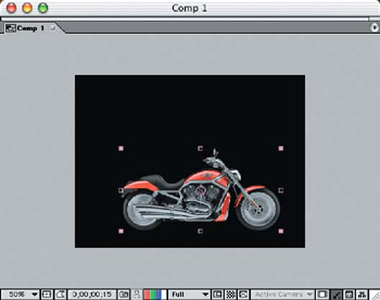
Figure 5.1: Place the single-layer image onto the Comp window in the lower third of the frame.
| Note |
As always, you can see the final effect we're after here by viewing the finished Inertia-Stop movie on the DVD. |
- We need to first move the motorcycle across the screen, setting the start and stop points on the Timeline. Move the Indicator on the Timeline down to the Frame 17 mark, press the P key, and click the Stopwatch to set the stop point keyframe.
- Move the Indicator back to the Frame 6 mark, and drag the motorcycle layer out of the frame off to the left so it's out of view (Figure 5.2).
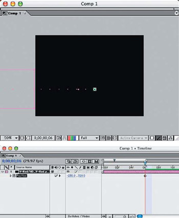
Figure 5.2: Create the start and stop points for the motion path of the motorcycle layer. - Move the Indicator down to approx a half second so the motorcycle is visible in the comp window. Apply the Transform effect to the motorcycle layer (Effect > Distort > Transform) and set the Skew to 20 at a +90 angle. Move the indicator to Frame 21 and click the Skew stopwatch to set the keyframe with the current amount of skew. Move the Indicator back to Frame 14 and set the amount of skew to 0.0, so the motorcycle isn't leaning all the way into the frame.
- The entire motorcycle skews from the center of the image, so we need to reposition the Anchor Point to the base of the motorcycle to make it lean forward at the tires. Click the Anchor Point crosshair button in the Effects palette, and set the position manually in the Comp window (Figure 5.3). Since the effect is applied to the layer, it will make the motorcycle jump up to the layer's Anchor Point to match.
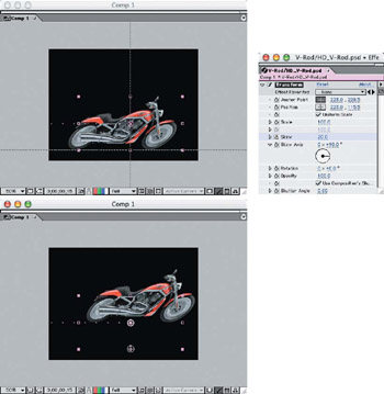
Figure 5.3: Apply a Skew effect to the layer, and reposition the Anchor Point to make the motorcycle lean forward.
To make the motorcycle appear to lean forward under the force of inertia, the timing of the skew placement is important. The longer it takes for the effect to move forward before the recoil, the more energy appears to be applied to the motorcycle. If it's a short "snap back," then either the vehicle wasn't traveling very fast or the mass is not that great.
- After the skew forward is applied, move the Indicator down a few frames and reverse the skew at a lesser degree, and then move back to the upright unskewed position at rest (Figure 5.4). Apply the settings for the position and the applied Skew effect from Table 5.1; then use RAM Preview to see the timing of the affect.
- To enhance the effect of the motorcycle's speed, let's add some motion blur. Select Effect > Blur & Sharpen > Directional Blur. Set the Direction to +90.0 and the Blur Length to 20.
- Move the Indicator to Frame 17 in the Timeline, and click the Blur Length Stopwatch to set the keyframe (Figure 5.5). Move the Indicator to Frame 20, and set the Blur Length to 0.0.
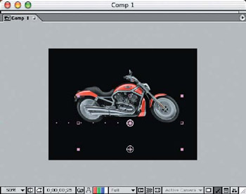
Figure 5.4: A reverse skew of a smaller degree provides the "snap back"of the effect.
|
Effects:Transform |
00;00 |
00;14 |
00;17 |
00;20 |
00;24 |
00;28 |
01;02 |
|---|---|---|---|---|---|---|---|
|
Anchor Point |
223, 228.5 |
||||||
|
Skew |
0.0 |
20.0 |
20.0 |
−5.0 |
0.0 |
||
|
Skew Axis |
+90.0∞ |
||||||
|
Transform |
|||||||
|
Position |
−230, 320 |
350, 320 |
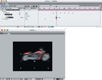
Figure 5.5: Adding motion blur to the motorcycle will enhance the illusion of speed.
Bouncing and Falling Defying the Rules of Gravity
You can give life to simple, inanimate objects by animating their movements. Merely falling off a ledge is easy, and the expected result is to just disappear quickly (like the orange slice in Chapter 4, "Applying Animation Concepts"). But give the object an expression of "Oh nooooooooo!" before the final fall, and it takes on a whole new meaning!
We're going to animate a single image of a pineapple that bounces across the frame and right off the edge. The slight delay before the stretch and then the fall will add to the characterization of this simple object.
Create a new project in After Effects and a new composition, 640480 NTSC, 3 seconds in length. Make the Rulers visible and drag down a guide horizontally approximately halfway. Import the image Pineapple.psd from the DVD and drag it to the Comp 1 window. Scale it to 50% and move it on top of the guide (Figure 5.6).
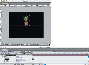
Figure 5.6: Import and scale the pineapple layer to fit on top of the guide.
| Note |
When you need to stretch, zoom, or scale up an image layer, make sure the original is at least as big as the largest scaled size or length of the stretch, so there won't be any loss of image quality. If you bring an image layer in at 100% and need to stretch it or scale it larger, you will experience image degradation and pixilation. |
To make the pineapple appear to "bounce" across the frame, we will move not only its position but also the vertical scale at the bottom of each bounce. We also need to adjust the angle of the pineapple on the approach and take-off of each bounce to move it forward.
Let's first create the position and scale path. Start with the Indicator on the Timeline at zero and drag the pineapple off the left side of the frame. Click both the Position and Scale Stopwatches and apply the settings in Table 5.2. This will set the keyframes for the basic motion path of the animation (Figure 5.7).
| Note |
When inserting variable settings on only one axis, make sure you deselect the link icon on the Timeline, or you will change all of the linked axis settings as well. |
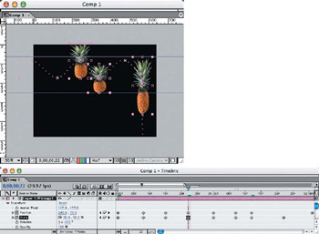
Figure 5.7: Set the keyframes for scale and position in the bounce and fall of the pineapple.
|
Transform |
00;00 |
00;08 |
00;15 |
00;23 |
01;00 |
01;07 |
01;15 |
01;22 |
02;00 |
|---|---|---|---|---|---|---|---|---|---|
|
Position |
−75.0, 172.0 |
−9.0, 82.0 |
123.0, 172.0 |
243.0, 79.0 |
341.0, 172.0 |
475.0, 82.0 |
558.0, 150.0 |
567.0, 205.0 |
574.0, 652.0 |
|
Scale (%) |
50.0, 40.0 |
50.0, 50.0 |
50.0, 40.0 |
50.0, 50.0 |
50.0, 40.0 |
50.0, 50.0 |
50.0, 50.0 |
45.0, 80.0 |
To give the effect of hang time, as we discussed in Chapter 3, "3-D Layers from Photoshop Layers," let's slow down the upper keyframes of the bounces by applying the Easy Ease Keyframe Assistant to both the Position and Scale keyframes (Figure 5.8). The default setting of 33.33% will be sufficient ease in and out of these points, occurring on each bounce.
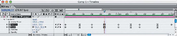
Figure 5.8: Create a little hang time at the top of the bounce.
Next we need to create the slight delay before falling off the ledge on the right side of the frame and apply the Easy Ease Keyframe Assistant to both the Position and Scale keyframes. Select the Keyframe Velocity for the Position keyframe only, and set it to 100% for both Incoming and Outgoing settings. Leave the Scale Keyframe Velocity settings at the default 33.33% (Figure 5.9).
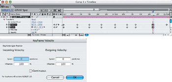
Figure 5.9: Set the Position Keyframe Velocity higher than Scale Velocity to produce the delay just before falling.
Now let's create the angles to the pineapple's motion that will give the illusion of it being propelled forward under its own power, similar to the animated vegetables in Veggie Tales. Move the indicator to zero in the Timeline, and apply the Transform effect to the pineapple layer. Click the Skew Stopwatch in the Timeline, and apply the settings in Table 5.3 (Figure 5.10).
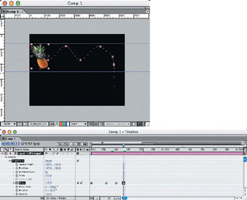
Figure 5.10: Apply the Skew effect to create the illusion of forward motion on the bounces.
|
Skew |
Keyframes |
|---|---|
|
15.0 |
00;00,00;06,00;17,00;20,01;02,and 01;05 |
|
−15.0 |
00;10,00;13,00;24,00;28,01;09,and 01;13 |
Run a RAM Preview to make sure the animation settings are correct and make corrections if necessary. You can compare the timing of your animation to the Quick-Time movie PineappleJump-320.mov, in the Chapter 5 folder on the DVD.
To give a more realistic look to the animation, we will apply some motion blur to the faster sections of the motion path. Apply the Directional Blur filter (Effect > Blur & Sharpen > Directional Blur), move the Indicator to the zero position on the Timeline, and click the Blur Length Stopwatch. Leave the Direction set at 0.0.
In the sections where the pineapple is moving up or down in the bounce, apply a Blur Length of 7.0, but apply a setting of 0.0 in the compressed bounce and "hang time" sections (as shown in Table 5.4).
|
Blur Length |
Keyframes |
|---|---|
|
7.0 |
00;00–00;06,00;10–00;13,00;17–00;20,00;24–00;28,01;02–01;05,and 01;09–01;13 |
|
0.0 |
00;08,00;15,00;22,01;00,01;07,and 01;18–01;22 |
|
25.0 |
01:27 |
The final fall of the animation gets a much larger amount of blur applied to it (25.0) since it's an exaggerated free-fall (Figure 5.11).
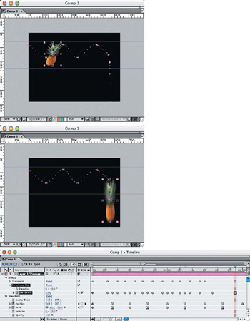
Figure 5.11: Applying a motion blur to the faster sections of the motion path will enhance the realism of the animation.
Rubber Planets 3 D Animation Effects
If you've ever watched Third Rock from the Sun on television, then you're familiar with the bouncing, dashing, crazy 3-D planet animations they ran during segment breaks. We can create very similar effects with two-dimensional animations of actual planet photos against a starry background. For this project, we'll use several animation tricks, such as exaggerated bounces, stops, falls, swings, and pop-ups. It's all about adjusting the motion paths, timing, speed, scale, and skew.
Since this will be a complex project with several animations all happening simultaneously, I'll concentrate on only one at a time. If you wish, you can open the After Effects project file, PlanetProject.aep, from the DVD and turn individual layers off and on to see the motion and effects paths.
Planet 1 Earth Stop
Create a new project in After Effects and a new composition, 640480 NTSC, 6 seconds in length. Import the Photoshop image files (Earth.psd, Moon.psd, Mars.psd, Saturn.psd, and Stars.psd) from the Chapter 5 folder on the DVD and drag them to the Comp 1 window. Hide all of the planet layers except Earth. Press A to reveal the Anchor Point, and set the X-axis to 0.0 so the Anchor Point will center on the left side of the planet layer (Figure 5.12). This will make the Earth jump over toward the right side of the frame.
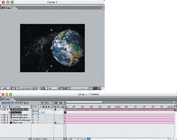
Figure 5.12: Hide all of the planet layers except Earth and reposition the Anchor Point.
With the Earth layer still in this position, move the Indicator to Frame 11 on the Timeline, and click the Position Stopwatch to set the current keyframe location. Move the Indicator to Frame 5 and set the X-axis position to –384.0 to move the Earth layer off the left side of the frame. This will be the extent of the motion path for this planet layer. The abrupt stop effect will be the focus of this animation.
Similar to the motorcycle project earlier in this chapter, we will be skewing this layer, but we will also be adjusting the horizontal scale—like a sideways bounce. This will give the stop animation a flapping, rubberized effect.
Starting at Frame 11, click the Scale Stopwatch on the Timeline to set the first keyframe. Move the Indicator down to Frame 13, set the X-axis scale per Table 5.5, and continue for every other keyframe until the animation ends at 100% at Frame 01;07 (Figure 5.13). The motion will regress as the Timeline continues.
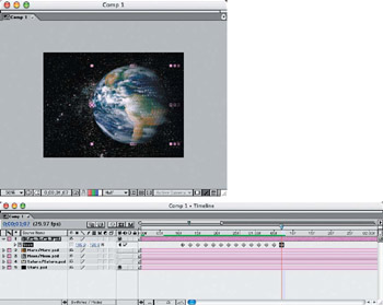
Figure 5.13: Set horizontal keyframes for the stop bounce animation.
Apply the Transform effect to the layer (Effect > Distort > Transform), and set the Skew Axis angle to +90.0. Click the Anchor Point crosshair button, and set the crosshairs on the bottom-left corner of the layer in the Comp window (Figure 5.14). The Anchor Point circle will appear in the middle of the Earth layer, so drag it down to the bottom-left corner to set it.
|
Keyframe |
Scale (X-Axis) |
Keyframe |
Scale (X-Axis) |
Keyframe |
Scale (X-Axis) |
|---|---|---|---|---|---|
|
00;11 |
100 |
00;21 |
105 |
01;01 |
98 |
|
00;13 |
110 |
00;23 |
95 |
01;03 |
100 |
|
00;15 |
90 |
00;25 |
103 |
01;05 |
99 |
|
00;17 |
107 |
00;27 |
97 |
01;07 |
100 |
|
00;19 |
93 |
00;29 |
101 |
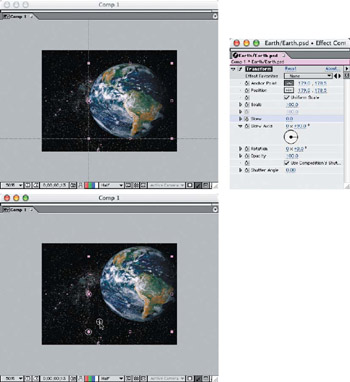
Figure 5.14: Set the Skew Anchor Point on the Earth layer to the bottom-left corner.
The Skew settings will match the Scale settings, so they will work together to create the rubberized effect. Apply the Skew settings in the regressive order shown in Table 5.6 until they return to the at-rest position at Frame 01;07 (Figure 5.15).
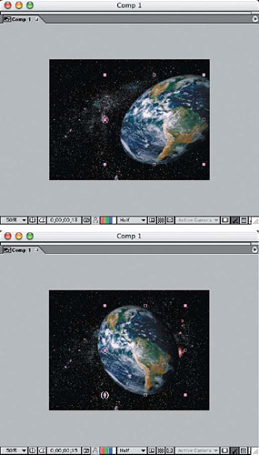
Figure 5.15: Apply the Skew effect to "rubberize" the Earth's movement.
|
Keyframe |
Skew |
Keyframe |
Skew |
Keyframe |
Skew |
|---|---|---|---|---|---|
|
00;10 |
0.0 |
00;21 |
10.0 |
01;01 |
−4.0 |
|
00;13 |
20.0 |
00;23 |
−6.0 |
01;03 |
3.0 |
|
00;15 |
−10.0 |
00;25 |
8.0 |
01;05 |
−5.0 |
|
00;17 |
12.0 |
00;27 |
−3.0 |
01;07 |
0.0 |
|
00;19 |
−8.0 |
00;29 |
5.0 |
We'll now add some motion blur to the animation to smooth out the fastest sections. Move the Indicator to Frame 10 on the Timeline and apply the Directional Blur filter. Set the Direction to +90.0, and click the Blur Length Stopwatch to set the keyframe, with a Blur Length of 15.0 (Figure 5.16). Move the Indicator to Frame 11 and set the Blur Length to 5.0; then move on to Frame 01;07 and set it to zero. Run a RAM Preview to check that all of the keyframes are placed correctly in the Earth animation.
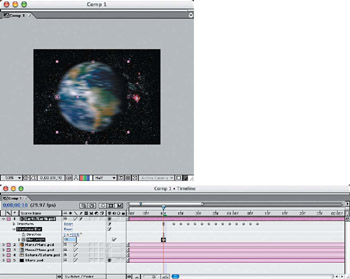
Figure 5.16: Applying motion blur to the faster sections of the motion path will enhance the realism of the animation.
| Note |
Since we will be moving the planets around in 3-D space, convert all of the planet layers to 3-D layers:Right-click/Ctrl+click each planet layer and select 3D Layer. However, don't convert the stars background layer, because we won't be moving it or casting shadows on it. |
Planet 2 Mars Bounce
We will animate Mars to fly in from the lower-left side of the frame and move back behind the Earth, bouncing off the right side, top, and then bottom of the frame before finally bouncing out into space and resting. This will require position and scale moves and manual adjustments of the Bezier curve handles on the keyframe points to control the motion path of the Mars layer.
Hide the Earth layer, and make the Mars layer visible. Start with the Indicator set at Frame 25, and assign the Position and Scale keyframes first, from Table 5.7. This will create our initial path where we can then adjust the Bezier curve handles (Figure 5.17).
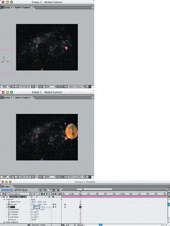
Figure 5.17: Set the Position and Scale keyframes for the Mars layer.
|
Transform |
00;25 |
01;05 |
01;11 |
01;19 |
01;26 |
02;03 |
02;10 |
02;15 |
|---|---|---|---|---|---|---|---|---|
|
Position |
−128.0, |
597.4, |
410.0, |
232.0, |
174.4, |
98.8, |
56.9, |
21.1, |
|
Scale (%) |
85.0, |
50.0, |
55.0, |
50.0, |
48.0, |
43.0, |
38.0, |
35.0, |
Once the keyframes are set, eliminate or contract the Bezier curve handles on the long bounce passes. Click the handles and drag them up to the keyframe Anchor Point, or use the Convert Vertex tool from the Tools palette to create straight motion paths, up to Frame 01;19 (Figure 5.18).
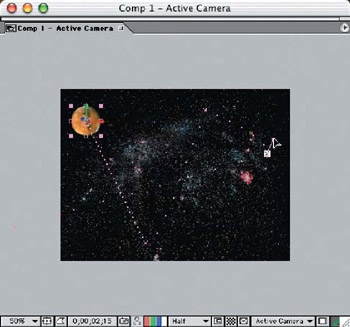
Figure 5.18: Minimize or eliminate the Bezier curves on the straight bounce paths.
Now that the general keyframes are set, we need to accentuate the bounce effects by forcing the scale from symmetrical to asymmetrical at the point of impact. We do this by checking the Scale dimensions at each keyframe and adding a new keyframe on either side, making the Scale dimensions symmetrical. For instance, at Frame 01;05, the Scale is 50.0, 60.0, 100.0. By adding a keyframe on either side and scaling the Mars layer to 60.0, 60.0, 100.0, the planet looks as if it is being compressed against the wall briefly (Figure 5.19).
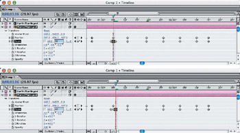
Figure 5.19: Adding symmetrically scaled keyframes on either side of the compressed keyframes will give the effect greater impact.
We want the ball to now bounce from keyframe 01;19 out into space. Right now, it merely slides out there. Selecting the keyframes out to the end of the motion path, one at a time, grab the right-side Bezier curve handle and pull it up to about the 1 o'clock position (Figure 5.20). Pull it out far enough to create a large arc with a rapid drop toward the top of the keyframe mark below. Repeat this process with the remaining few keyframes, progressively decreasing the amount of arc on each keyframe. For these detailed steps, I hid the background stars layer so I could see the path dots and handles more clearly.
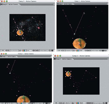
Figure 5.20: Pull out the Bezier curve handles to create the final Mars bounce sequence.
| Note |
Since the process of adjusting the Bezier curve handles is subjective—not absolute—you may want to run several RAM Previews of your animation and make slight adjustments until it looks "just right." |
To smooth out the animation and give it pleasing realism, let's add some motion blur to the faster moving segments. This animation is going to require a more complicated Directional Blur for all the directions the planet layer is traveling in the frame. For instance, the first path segment requires a longer blur length and angle than the rest of the segments, since it's traveling at the fastest rate of speed and the farthest distance (Figure 5.21). We'll set the Directional Blur to zero on the bounce keyframes to accentuate the effect and ensure that the viewer will see the compressed sphere (Figure 5.22). Follow the Directional Blur settings in Table 5.8 to complete the Mars layer animation.
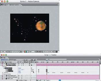
Figure 5.21: Apply motion blur in the direction the object is traveling and change it for each direction.
|
Effects: |
00;26–01;04 |
01;05 |
01;06–01;10 |
01;11 |
01;12–01;18 |
01;19 |
01;20 |
01;25 |
|---|---|---|---|---|---|---|---|---|
|
Direction |
0 x –110.0∞ |
0 x +135.0∞ |
0 x +35.0∞ |
0 x +155.0∞ |
||||
|
Blur Length |
35.0 |
0.0 |
33.0 |
0.0 |
30.0 |
0.0 |
18.0 |
0.0 |
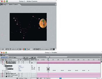
Figure 5.22: Make sure the motion blur is turned off on the compressed bounce frames to enhance the effect.
Planet 3 Moon Pop Up
The moon will take a wide sweep around and behind the Earth layer and pop up in front of it. To keep the motion fluid, we will use only a couple of keyframes with large Bezier curve arcs. We will end with a series of short position and scale movements— similar to the rubberized effect we gave the Earth layer.
We'll start with the moon off the left side of the frame at the 2-second mark and scaled down to 50%. We will then give it two more keyframes in order to create the curve and position we need for it to move behind and in front of the Earth. Using Table 5.9, apply the first three Position and Scale keyframes, stopping at Frame 02;19. Then drag the Bezier curve handles on the first two keyframes to create a smooth arc (Figure 5.23).
|
Transform |
02;00 |
02;15 |
02;19 |
02;22 |
02;25 |
02;27 |
02;29 |
03;01 |
03;03 |
|---|---|---|---|---|---|---|---|---|---|
|
Position |
−170.0, |
801.0, |
635.3, |
455.0, |
480.0, |
460.0, |
477.0, |
465.0, |
475.0, |
|
Scale (X and Y,%) |
35.0 |
50.0 |
70.0 |
85.0 |
70.0 |
83.0 |
73.0 |
80.0 |
76.0 |
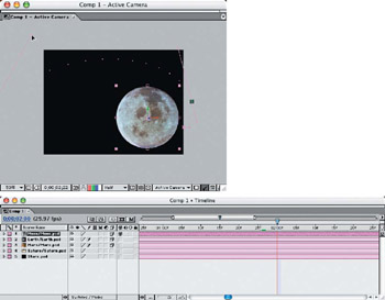
Figure 5.23: Drag the Bezier curve handles to create an arc in the motion path.
Continue adding the keyframes for the rest of the animation per Table 5.9, and run a RAM Preview to make sure your numbers are entered correctly. Keep in mind that the exact numbers aren't as important as how good the animation looks to you. It's a subjective process and your eyes will be your best judge. These numbers are only a guideline.
We'll add motion blur to the moon layer animation, changing the angle at keyframes to follow the direction of travel (Figure 5.24). The Directional Blur effect decreases toward the end of the motion path but overlaps for the first big pop-up. Follow Table 5.10 for the Directional Blur keyframe settings.
|
Effects:Transform |
02;00 |
02;10 |
02;13 |
02;22 |
02;25 |
02;29 |
|---|---|---|---|---|---|---|
|
Direction |
0 x +76.0∞ |
0 x +105.0∞ |
0 x +184.0∞ |
0 x +220.0∞ |
||
|
Blur Length |
35.0 |
35.0 |
10.0 |
0.0 |
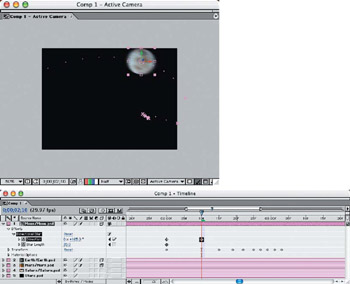
Figure 5.24: Add a Directional Blur to the moon layer animation.
Planet 4 Saturn Drop
We will have Saturn drop straight down as if it's on an imaginary string and suddenly reaches the end of the line with a jerk. The layer moves in only one direction, so we only need to apply position and scale keyframes and add a single-direction motion blur.
Since we want to give the illusion that the Saturn layer is suspended from an imaginary string by the center of its sphere, we will move the Anchor Point up the center to 50.0 in the Y-axis. This will allow the scale to "tilt" the planet slightly when it bounces at the end of the string. Starting at the 3-second mark, add Position and Scale keyframes per Table 5.11 (Figure 5.25).
|
Transform |
03;00 |
03;08 |
03;10 |
03;14 |
03;17 |
03;20 |
03;23 |
03;26 |
03;28 |
04;00 |
04;02 |
04;04 |
|---|---|---|---|---|---|---|---|---|---|---|---|---|
|
Position |
170.0, |
170.0, |
170.0, |
170.0, |
170.0, |
170.0, |
170.0, |
170.0, |
170.0, |
170.0, |
170.0, |
|
|
Scale (Y-axis,%) |
100.0 |
130.0 |
90.0 |
115.0 |
93.0 |
105.0 |
96.0 |
103.0 |
98.0 |
102.0 |
100.0 |
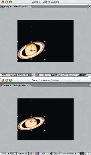
Figure 5.25: Slightly offsetting the Anchor Point up from the center will give the animation a more 3-D illusion.
Of course, now we need to add motion blur to this animation—and where would we be without it! Apply the Directional Blur filter in the default direction of 0.0. Move the Indicator to Frame 03;08, click the Blur Length Stopwatch, and set it to 35.0 (Figure 5.26). Then at Frame 03;10, set the Blur Length to 0.0. This will let the planet layer fall straight down smoothly and then come into focus right at the snap-up. Move the Indicator down two frames to 03:12 and set the Blur Length to 5.0; then set it back to 0.0 at 03;14. This will give the initial snap-up a brief motion blur before the final bounces.
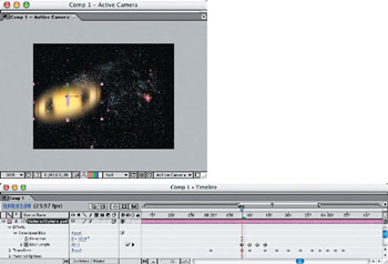
Figure 5.26: Directional Blur is applied to the Saturn layer for the main drop, plus a little on the initial snap-up motion.
Completing the Scene Adding Lights
To give the 3-D layer effect its depth and richness, we need to add lights to the scene. Start by adding an ambient light (Layer > New > Light) and selecting the Ambient Light Type. Set the Intensity to 35% and select a warm yellow color (Figure 5.27). This light does not cast shadows but only warms up the scene after we add the spotlight, so the scene will appear fairly dark at this point.
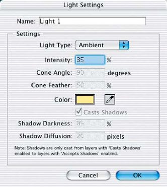
Figure 5.27: Add an ambient light that will warm up the shadow areas in the final scene.
Add a spotlight to the scene (again, Layer > New > Light) and choose the Spot Light Type. Set the Intensity to 80, and select a lighter hue of the yellow you used for the ambient light. Set the Shadow Darkness to 85 and the Diffusion to 20 (Figure 5.28).
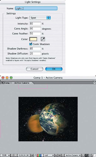
Figure 5.28: Add a spotlight to the scene—this will become the Sun's light source.
Select the Left side view window, and reduce the scale of the frame viewing area to better access the Spot. Click the Spot wireframe (without selecting the X-, Y-, or Z-axis handles), and then drag the light down and out to under the 3 o'clock position. Drag the Point Of Interest handle down to the Earth layer's center (Figure 5.29). Switch to the Front side view window, and drag the Spot wireframe over to the left side, just above the 8 o'clock position. This angle should light up the entire scene well and cast shadows in the right places.
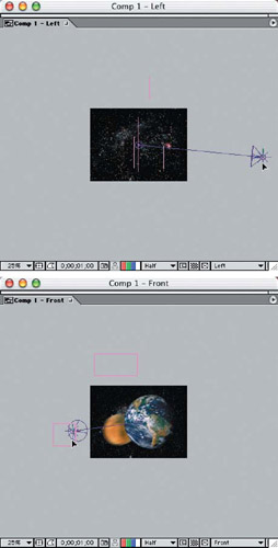
Figure 5.29: Move the spotlight into position to closely match the original position of the Sun to the planet image layers.
Select each planet layer in the Timeline, and open Material Options and turn on the Casts Shadows option (Figure 5.30). Move the Indicator to a point where two planets intersect, and notice the shadow that is cast on the planet layer in the background.
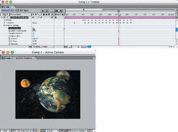
Figure 5.30: Turn on the Casts Shadows option for all of the planet layers.
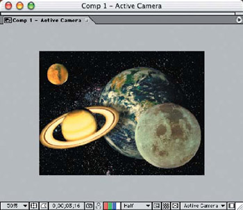
When all of the planets are in the frame toward the end of the animation, you'll have a collection of planets casting shadows on one another in a fantasy scene. What's more, you've just applied several concepts of animation in a 3-D environment that you can apply to your motion graphics and titling projects.
Kinematics Human Figure Character Animation
Kinematics, in computer graphics language, is motion created by the force of another material body in motion—usually something that's attached, like a hand is to an arm. If the arm is moved, then the hand must go with it, even though the hand is still free to move on its own.
This is something usually practiced by 3-D character modelers who create video games and animated motion pictures. Fortunately, After Effects gives us some pretty powerful tools to accomplish kinematic motion on two-dimensional characters that can really fool the eye!
For these examples, I've taken a single stock image of a skeleton that had an alpha channel already created, and I tore it to bits! You'll find the Photoshop image, SkeletonSmall.psd, on the DVD, so you can see the many layers that were created out of this original image (Figure 5.31).
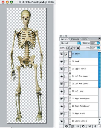
Figure 5.31: Open the skeleton Photoshop file to examine how the layers are created and how they go together.
Create a new project file in After Effects, and import the file SkeletonSmall.psd as a composition to retain the layer information. Open the composition from the Project window, and edit the Composition Settings to resize it and allow more side-to-side motion when animating the layers.
Determine a central point of the body, which all the other parts can link to and move naturally. I've chosen the upper torso layer, where the arms, neck, and spine can connect to it. From this point, we will work out from the upper torso through all of the extremities. You may want to at least peek at the After Effects project file, Skeleton_Practice.aep, on the DVD, to follow along until you get the hang of what we're doing.
The Knee Bone s Connected to the Leg Bone
Connecting the layered pieces together will require important techniques: proper positioning of the Anchor Points and parenting the layers. The Anchor Points need to be located on each layer where the swivel point of the joint would naturally move. This is where it will be "connected" to the layer it is parented to.
Moving the Anchor Point on each layer requires you to open each layer in its own window and zoom in so you can really see what you're doing! Drag the Anchor Point to the joint or nearest connector point where it can swivel around (Figure 5.32).
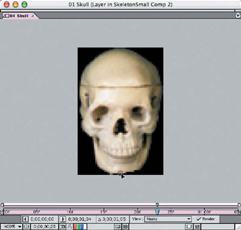
Figure 5.32: Zoom in on each layer and reposition the Anchor Points where they connect with other pieces.
To "connect" the layers, we use the Parent option on the Timeline. This doesn't really completely connect the layers, but it does allow you to move the parented layer and have those layers attached to it move with it. Parenting also allows you to rotate layers, and they will rotate around the Anchor Point that you positioned at the joint, so they will appear to be attached to the parented layer.
Let's look at a smaller segment to further understand how this works. Hide all of the layers except for the two left arm layers and the left hand layer. With the Anchor Points at the joints connecting to the preceding layer, select the preceding layer as a parent layer using the Parent Layer Selector on the Timeline (Figure 5.33). Rotate the lower arm layer and see how it moves at the elbow. Rotate the hand layer, and it should bend at the wrist. Move or rotate the upper arm layer, and both the lower arm and hand move with it.
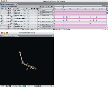
Figure 5.33: Experimenting with a small section of the skeleton will help you understand the physics of the motion and how the layers work together.
With everything parented in all the way to the upper torso layer, you should be able to move the layer, and the whole skeleton will move with it. If you rotate the upper torso slightly, you will need to rotate the spine segments, lower torso, and legs to bring the feet back down to the ground (Figure 5.34).
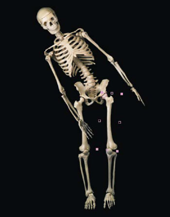
Figure 5.34: Rotate the upper torso layer, spine segments, and lower torso layer to see how twisting the body makes the rest of the limbs react.
Making adjustments to all of the limbs from this position, you can start to emulate graceful movements (Figure 5.35). It's like combining a stop-motion wire figure animator with a puppeteer. With a little creativity and finesse, you can really have fun animating your skeleton character!
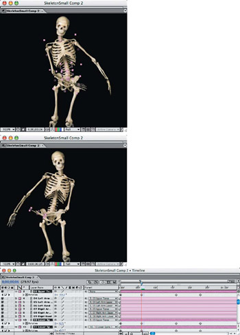
Figure 5.35: Some experimentation and practice will help you get the feel for putting your character in motion.
In some cases, you will need to adjust the length of a foot, arm, or leg segment to give the appearance of upward or downward motion in the Z-axis—even though there is no Z-axis present in a two-dimensional animation (Figure 5.36).
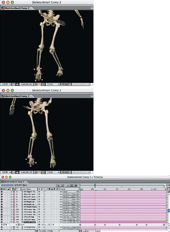
Figure 5.36: Scale the length of a segment to adjust for the lack of a Z-axis in a two-dimensional animation.
Kinematic Animation Example
Let's make a simple animation that moves every layer in our skeleton, simply by rotating layers with kinematic motion. Using the principles previously covered, we'll build this animation keyframe by keyframe, instead of layer by layer.
Because of the possible variations in building your model, it would be best to use the file Skeleton_Practice.aep from the DVD. The parent layers have already been applied, so all you have to do is follow the settings in Table 5.12 and study what is happening in each layer's rotation.
|
Layer Transform |
00;00 |
00;06 |
00;08 |
00;10 |
00;16 |
00;23 |
00;25 |
00;26 |
01;04 |
|---|---|---|---|---|---|---|---|---|---|
|
01 Skull |
−0.8 |
+11.1 |
+0.5 |
−14.3 |
−1.9 |
||||
|
02 Neck |
−0.3 |
+11.7 |
−3.1 |
−16.5 |
+0.8 |
||||
|
03 Upper Torso |
+1.1 |
−10.2 |
+4.7 |
+17.5 |
+1.0 |
||||
|
04 Left Arm Upper |
+0.0 |
−13.9 |
−17.5 |
−4.6 |
−0.3 |
+23.3 |
+15.5 |
−1.1 |
|
|
05 Left Arm Lower |
+6.2 |
−35.5 |
−58.0 |
−3.3 |
−14.6 |
+5.2 |
−7.1 |
+8.6 |
|
|
06 Left Hand |
−7.4 |
−16.9 |
−9.7 |
||||||
|
07 Right Arm Upper |
−0.9 |
−22.9 |
−29.2 |
−23.7 |
−6.6 |
+11.5 |
+3.5 |
+0.2 |
|
|
08 Right Arm Lower |
−5.0 |
−4.0 |
−10.0 |
+10.0 |
−1.4 |
+39.6 |
+48.4 |
−8.2 |
|
|
09 Right Hand |
+5.2 |
+27.8 |
+41.2 |
+24.5 |
+12.7 |
||||
|
10 Lower Spine 1 |
+1.1 |
+2.5 |
−3.7 |
−5.7 |
−1.3 |
||||
|
11 Lower Spine 2 |
+0.0 |
+5.7 |
−4.1 |
−5.0 |
−1.3 |
||||
|
12 Lower Torso |
+1.4 |
+13.0 |
+5.9 |
−1.6 |
+5.2 |
||||
|
13 Left Hip |
−5.6 |
−8.7 |
−9.4 |
−8.1 |
−15.2 |
−20.7 |
−15.8 |
−4.2 |
|
|
14 Left Shin |
+2.8 |
+6.5 |
+7.5 |
+9.9 |
+23.1 |
+48.7 |
+35.5 |
+0.1 |
|
|
15 Left Foot |
−6.1 |
−15.0 |
−9.2 |
−18.6 |
−45.2 |
−52.8 |
−43.1 |
−4.7 |
|
|
16 Right Hip |
+2.2 |
+10.5 |
+16.2 |
+9.7 |
+2.6 |
−5.1 |
−0.5 |
+4.7 |
|
|
17 Right Shin |
+0.0 |
−43.6 |
−55.8 |
−35.1 |
−3.2 |
−6.4 |
|||
|
18 Right Foot |
−11.0 |
+26.9 |
+25.3 |
−3.5 |
−3.6 |
−8.9 |
−5.1 |
| Note |
If you would like to see the completed After Effects files in their entirety, open SkeletonProject1.aep and SkeletonProject2.aep on the DVD and compare them to the projects in this section. You can also view the completed QuickTime movies of the completed animations. |
Details in Kinematic Animations
Subtle movements and fine details are what give realism to figure animation. Though this skeleton doesn't have individual moving fingers and toes, you can still apply movement that emulates a real figure, just by keeping constant motion present in small amounts.
The effects of kinematic motion are most noticeable when you are applying them to shoulders or hips, where there are many intersecting points. The tilt of a shoulder will cause necessary adjustments of the head and neck, as well as of the arms and the lower spine. Something as simple as crossing the arms or shifting to one foot causes a ripple effect throughout the entire body—like the sample animation I've included, SkeletonProject2.aep, located in the Chapter 5 project folder on the DVD.
When creating animations that require precision in movement, it's necessary to use rulers and guides to keep track of where your character is moving. While you are concentrating on the upper body, the legs may shift out from under you, and before you know it, you end up with a floating ghost with dangling legs!
While shifting the weight of the figure to one foot, you can see how much the rest of the body is influenced by this move (Figure 5.37). When the leg crosses over, the hips swivel upward, the spine adjusts to keep the head and upper body level, and the body comes to rest centered over the standing leg.
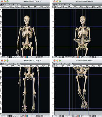
Figure 5.37: Using guides is very important to track your motion and make sure everything lines up correctly.
Part I - Connecting Photoshop, ImageReady, and After Effects
- Basic ImageReady Animation, Tweening, and Layer Styles
- Photoshop Layers and After Effects
- 3-D Layers from Photoshop Layers
Part II - Applying Animation Concepts
Part III - Clean-Up, Mattes, and Objects
- Blue-Screen Garbage Mattes
- Rotoscoping Techniques with Photoshop
- Matte and Keying Plug-ins
- Static Matte Painting in Photoshop
- Motion Matte Painting in Photoshop
- Making Movies from Stills
Part IV - Advanced Movie Magic
EAN: 2147483647
Pages: 104
