Using Antennas to Tailor Coverage
It may be necessary to provide coverage for a unique area that doesn't "play by the rules" you expect it to follow. Most access points use omnidirectional antennas, which radiate equally in every direction. However, it may be desirable to change the basic radio coverage pattern from a circle to something else for some applications. This is work that is often done in the field to adjust coverage from an AP to match a particular area, or to boost the signal to fill in a hole. With the cost of APs declining rapidly, custom tailoring coverage with antennas is not as necessary as it previously was, although it is still important.
In the past, radio equipment vendors needed to supply antennas and ensure that the capabilities of the combined system would meet the unlicensed spectrum transmission rules. In July 2004, the FCC relaxed the rules to allow a radio device manufacturer to specify a maximum gain and allow the user to select any antenna with the same gain characteristics.[*] Before the ruling, radios and antennas had to be certified as a single unit, and it was technically illegal to attach an antenna from a source other than the radio vendor. With the new rules, manufacturers can certify a system at the limits of the radio rules, and end users can choose any antenna within that outer boundary. If, for example, the radio manufacturer underwent certification testing with a 10 dBi antenna, a buyer is allowed to find a lower gain version of the same type of antenna (say, only 8 dBi), and use it legally.
[*] See document 04-165 at http://hraunfoss.fcc.gov/edocs_public/attachmatch/FCC-04-165A1.pdf, which modifies the relevant telecommunications rules.
Antenna Types
Wireless cards all have built-in antennas, but these antennas are, at best, minimally adequate. If you were planning to cover an officeor an even larger area, such as a campusyou will almost certainly want to use external antennas for your access points. When considering specialized antennas, there are only a few specifications that you need to pay attention to:
Antenna type
The antenna type determines its radiation patternis it omnidirectional, bidirectional, or unidirectional? Omnidirectional antennas are good for covering large areas; bidirectional antennas are particularly good at covering corridors; unidirectional antennas are best at setting up point-to-point links between buildings, or even different sites.
Gain
The gain of the antenna is the extent to which it enhances the signal in its preferred direction. Antenna gain is measured in dBi, which stands for decibels relative to an isotropic radiator. An isotropic radiator is a theoretical beast that radiates equally in all directions. To put some stakes in the ground: I've never seen a specification for the gain of the built-in antenna on a wireless card, but I would guess that it's negative (i.e., worse than an isotropic radiator). Simple external antennas typically have gains of 3 to 7 dBi. Directional antennas can have gains as high as 24 dBi.[*]
[*] If you want one more stake, the radio telescope at Arecibo has a gain in excess of 80 dBi.
Half-power beam width
This is the width of the antenna's radiation pattern, measured in terms of the points at which the antenna's radiation drops to half of its peak value. Understanding the half-power beam width is important to understanding your antenna's effective coverage area. For a very high-gain antenna, the half-power beam width may be a narrow angle. Once you get outside the half-power beam width, the signal typically drops off fairly quickly, although that depends on the antenna's design. Don't be fooled into thinking that the half-power beam width is irrelevant for an omnidirectional antenna. A typical omnidirectional (vertical) antenna is only omnidirectional in the horizontal plane. As you go above or below the plane on which the antenna is mounted, the signal decreases.
We've discussed antennas entirely in terms of their properties for transmitting, largely because most people find that easier to understand. Fortunately, an antenna's receiving properties are identical to its transmitting propertiesan antenna enhances a received signal to the same extent that it enhances the transmitted signal. This result is probably what you would expect, but proving it is beyond the scope of this book. Now, let's talk about some of the antenna types that are available (Figure 23-5 shows a number of different antenna types):
Vertical
This is a garden-variety omnidirectional antenna. Most vendors sell several different types of vertical antenna, differing primarily in their gain; you might see a vertical antenna with a published gain as high as 10 dBi or as low as 3 dBi. How does an omnidirectional antenna generate gain? Remember that a vertical antenna is omnidirectional only in the horizontal plane. In three dimensions, its radiation pattern looks something like a donut. A higher gain means that the donut is squashed. It also means that the antenna is larger and more expensive, although no antennas for 802.11 service are particularly large.
If you want to cover a confined outdoor areafor example, a courtyard between several buildings of a corporate campusnote that the half-power beam width means that a roof-mounted vertical antenna might be less than ideal, particularly if the building is tall. Vertical antennas are good at radiating out horizontally; they're not good at radiating down. In a situation like this, you would be better off mounting the antenna outside a first-or second-story window.
Figure 23-5. Antenna types
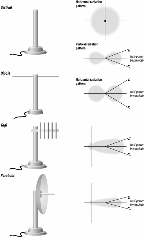
Dipole
A dipole antenna has a figure-eight radiation pattern, which means it's ideal for covering a hallway or some other long, thin area. Physically, it won't look much different from a verticalin fact, some vertical antennas are simply vertically mounted dipoles.
Yagi
A Yagi antenna is a moderately high-gain unidirectional antenna. It looks somewhat like a classic TV antenna. There are a number of parallel metal elements at right angles to a boom. However, you are not likely to see the elements on a Yagi for 802.11 service; the commercially made Yagis that I have seen are all enclosed in a radome, which is a plastic shell that protects the antenna from the elements in outdoor deployments. Yagi antennas for 802.11 service have gains between 12 and 18 dBi; aiming them is not as difficult as aiming a parabolic antenna, although it can be tricky.
Parabolic
This is a very high-gain antenna. Because parabolic antennas have very high gains (up to 24 dBi for commercially made 802.11 antennas), they also have very narrow beam widths. You would probably use a parabolic antenna only for a link between buildings; because of the narrow beam width, they are not very useful for providing services to end users. Vendors publish ranges of up to 20 miles for their parabolic antennas. Presumably, both ends of the link are using a similar antenna. Do not underestimate the difficulty of aiming a parabolic antenna properlyone commercial product has a published beam width of only 6.5 degrees. If you decide to install a parabolic antenna, make sure that you have it mounted firmly. You do not want a bad storm to nudge it a bit and take down your connection.
Some vendors make an issue of the distinction between "mesh" or "grid" parabolas (in which the antenna's reflector looks like a bent barbecue grill) and solid parabolas. Don't sweat itif the antenna is well-designed, the difference in performance between a mesh and a solid reflector is not worth worrying about. A mesh does have an advantage, though, in areas subject to high winds.
Parabolic and Yagi antennas are useful primarily for links between buildings. The biggest problem is aiming them properly. If the two sites are visible to each other, you can play some tricks with gunsightsalthough if you can see one site from the other, you probably don't need such a sophisticated antenna system. Otherwise, buy a good compass and a topographical map from the U.S. Geological Survey, and compute the heading from one site to the other. Remember to correct for magneticNorth. If you can spend some extra money, you might be able to simplify the setup by installing a high-gain vertical antenna at one site; then you need to aim only one antenna. If the signal is marginal, replace the vertical with a parabolic antenna once you have the first antenna aimed correctly.
High-gain antennas can become a regulatory problem, particularly in Europe, because transmission power limits are lower than in the U.S. The high-gain parabolic antenna sold under the Orinoco brand cannot legally be used at the edges of the ISM band in the U.S. (1, 2, 10, and 11 are excluded) because of signal leakages outside the band.
Antenna cabling
Having put so much effort into thinking about antennas, we have to spend some time thinking about how to connect the antennas to the access points or wireless cards. Most vendors sell two kinds of cable: relatively inexpensive thin cable (typically 0.1 inch in diameter) and "low-loss cable" that's substantially thicker (typically 0.4 inch) and much more expensive. The thin cable is usually available only in lengths of a couple of feet, and that is as it should be: it is very lossy, and more than a few feet can easily eat up your entire signal. One site I worked at concealed APs by mounting them above the ceiling and using an unobtrusive external antenna poking through the ceiling tile. However, the mounting scheme turned out to be a wash. The external antennas had a 2 dB gain, and the cable connecting the antennas to the APs had a 2 dB loss.
Thin cable is intended for connecting a wireless card in a laptop to a portable antenna on your desktop, and that is about all it is good for. To put numbers behind this: one vendor specifies a loss of 2.5 dB for a 2-meter cable. That means that close to half of your signal strength is disappearing in just two meters of cable. One cable vendor, for a cable that would typically be used in this application, specifies a loss of 75 dB per 100 feet at 2.4 GHz. That means that your signal strength will drop by a factor of 225 (roughly 33 million), clearly not something you want to contemplate. I know of one vendor that recommends using RG58 cable with medium-gain antennas. RG58 is better than the really thin cable intended for portable use, but not much better (35 dB per 100 feet); if you use RG58 cable, keep the cable run as short as possible. Better yet, ditch the RG58 and see xsif you can replace it with LMR-200 (a high-quality equivalent with half the loss).
What does the picture look like when you're using a real low-loss cable? Significantly better, but maybe not as much better as you would like. A typical cable for this applicationused by at least one 802.11 vendoris Times Microwave LMR-400. LMR-400 is a very high-quality cable, but it still has a loss of 6.8 dB per 100 feet at 2.4 GHz. This means that, in a 100-foot length of cable, over three quarters of your signal is lost. The moral of the story is clear: keep your access points as close as possible to your antennas. Minimize the length of the transmission line. If you want a roof-mounted antenna, perhaps to cover a courtyard where people frequently have lunch, don't stick your access point in a wiring closet in the basement and run a cable to the roof. If possible, put your access point in a weatherproof enclosure on the roof. If that's not possible, at least put the access point in an attic or crawlspace. There is no substitute for keeping the transmission line as short as possible. Also, keep in mind that transmission lines have a strange ability to shrink when they are routed through walls or conduits. I've never understood why, but no matter how carefully you measure, you are certain to find that your cable is two feet short. More to the point: the straight-line distance from your access point to the antenna may be only 20 feet, but don't be surprised if it takes a 50-foot cable to make the trip. The cable will probably have to go around corners and through conduits and all sorts of other misdirections before it arrives at its destination.
Finally, there's the matter of antenna connectors. All wireless vendors sell cables in various length with the proper connectors and adapters. I strongly recommend taking the easy way out and buying cables with the connectors preinstalled. Connector failure is one of the most common causes for outages in radio systems, particularly if you don't have a lot of experience installing RF connectors.
Antenna diversity
One common method of minimizing multipath fading is to have antenna diversity. Rather than making the antenna larger, radio systems can use multiple antennas and choose the signal from the antenna with better reception. Using multiple antennas does not require sophisticated mathematical theory or signal-processing techniques.
Several wireless LAN vendors have built multiple antennas into wireless network cards. Some vendors even offer the ability to connect multiple external antennas to network cards intended for access points. Antenna diversity is recommended by the 802.11 standard, but it is not required. For environments with large amounts of interference, antenna diversity is a worthwhile option to consider when selecting vendors.
Amplifiers: bring on the heat
Amplifiers increase the power of a signal. On the transmission side of a radio network, amplifiers help fling the signal farther to cover more area. Many transmission amplifiers also incorporate preamplifiers for the reception side of the circuit as well, which helps increase the receiver's sensitivity to weak signals.
Indoor deployments of 802.11 typically do not not need amplifiers to increase transmission power. As an AP's transmit power increases, its coverage area can encompass more area, and more stations can join the network. To preserve quality coverage, it is best to design a network consisting of many small APs with relatively low transmit power. Even a wireless LAN deployment focused on providing coverage only, regardless of quality, although a large area is probably able to get by with a high-gain vertical antenna.
Generally speaking, high transmit power sounds like a much better idea than it is in practice, with a few obvious exceptions. Community networks may want to provide coverage for a large area before increasing the density of coverage, and APs may be more expensive than the amplification parts. Point-to-point links built on 802.11 are also a good application for amplification. If the distance is sufficiently large, all the antenna gain in the world won't pull the signal off the noise floor. One of the better-documented outdoor point-to-point shots is the uplink for the Ruby Ranch Internet Cooperative (http://www.rric.net).[*] Remote ISPs building their WANs on 802.11 may also make extensive use of amplification.
[*] The RRIC is a fascinating site in its own right, and I highly recommend it. The incumbent telephone carrier refused to deliver DSL in the neighborhood, so a group of committed volunteers made it happen.
SSB Electronics (www. ssbusa.com/wireless.html) and HyperLink Technologies (http://www.hyperlinktech.com/ web/amplifiers_2400.html) are two vendors of 802.11 amplifiers. However, if you use amplifiers with 802.11, remember:
- Stay within the legal power limit, both for absolute power and ERP.
- 802.11 is an unlicensed service. If you interfere with another service, it is your problem, by definition. And if a licensed service interferes with you, it is your problem, by definition. Interference is more likely to be a problem if your network covers a large service area and if you are using high power.
- Use equipment that is approved for 802.11 service. Other amplifiers are available that cover the frequency range, but using them is illegal.
|

Introduction to Wireless Networking
- Introduction to Wireless Networking
- Why Wireless?
- What Makes Wireless Networks Different
- A Network by Any Other Name...
Overview of 802.11 Networks
- Overview of 802.11 Networks
- IEEE 802 Network Technology Family Tree
- 11 Nomenclature and Design
- 11 Network Operations
- Mobility Support
11 MAC Fundamentals
- 11 MAC Fundamentals
- Challenges for the MAC
- MAC Access Modes and Timing
- Contention-Based Access Using the DCF
- Fragmentation and Reassembly
- Frame Format
- Encapsulation of Higher-Layer Protocols Within 802.11
- Contention-Based Data Service
- Frame Processing and Bridging
11 Framing in Detail
- 11 Framing in Detail
- Data Frames
- Control Frames
- Management Frames
- Frame Transmission and Association and Authentication States
Wired Equivalent Privacy (WEP)
- Wired Equivalent Privacy (WEP)
- Cryptographic Background to WEP
- WEP Cryptographic Operations
- Problems with WEP
- Dynamic WEP
User Authentication with 802.1X
- User Authentication with 802.1X
- The Extensible Authentication Protocol
- EAP Methods
- 1X: Network Port Authentication
- 1X on Wireless LANs
11i: Robust Security Networks, TKIP, and CCMP
- 11i: Robust Security Networks, TKIP, and CCMP
- The Temporal Key Integrity Protocol (TKIP)
- Counter Mode with CBC-MAC (CCMP)
- Robust Security Network (RSN) Operations
Management Operations
- Management Operations
- Management Architecture
- Scanning
- Authentication
- Preauthentication
- Association
- Power Conservation
- Timer Synchronization
- Spectrum Management
Contention-Free Service with the PCF
- Contention-Free Service with the PCF
- Contention-Free Access Using the PCF
- Detailed PCF Framing
- Power Management and the PCF
Physical Layer Overview
- Physical Layer Overview
- Physical-Layer Architecture
- The Radio Link
- RF Propagation with 802.11
- RF Engineering for 802.11
The Frequency-Hopping (FH) PHY
- The Frequency-Hopping (FH) PHY
- Frequency-Hopping Transmission
- Gaussian Frequency Shift Keying (GFSK)
- FH PHY Convergence Procedure (PLCP)
- Frequency-Hopping PMD Sublayer
- Characteristics of the FH PHY
The Direct Sequence PHYs: DSSS and HR/DSSS (802.11b)
- The Direct Sequence PHYs: DSSS and HR/DSSS (802.11b)
- Direct Sequence Transmission
- Differential Phase Shift Keying (DPSK)
- The Original Direct Sequence PHY
- Complementary Code Keying
- High Rate Direct Sequence PHY
11a and 802.11j: 5-GHz OFDM PHY
- 11a and 802.11j: 5-GHz OFDM PHY
- Orthogonal Frequency Division Multiplexing (OFDM)
- OFDM as Applied by 802.11a
- OFDM PLCP
- OFDM PMD
- Characteristics of the OFDM PHY
11g: The Extended-Rate PHY (ERP)
- 11g: The Extended-Rate PHY (ERP)
- 11g Components
- ERP Physical Layer Convergence (PLCP)
- ERP Physical Medium Dependent (PMD) Layer
A Peek Ahead at 802.11n: MIMO-OFDM
11 Hardware
- 11 Hardware
- General Structure of an 802.11 Interface
- Implementation-Specific Behavior
- Reading the Specification Sheet
Using 802.11 on Windows
11 on the Macintosh
Using 802.11 on Linux
- Using 802.11 on Linux
- PCMCIA Support on Linux
- Linux Wireless Extensions and Tools
- Agere (Lucent) Orinoco
- Atheros-Based cards and MADwifi
- 1X on Linux with xsupplicant
Using 802.11 Access Points
- Using 802.11 Access Points
- General Functions of an Access Point
- Power over Ethernet (PoE)
- Selecting Access Points
- Cisco 1200 Access Point
- Apple AirPort
Logical Wireless Network Architecture
- Logical Wireless Network Architecture
- Evaluating a Logical Architecture
- Topology Examples
- Choosing Your Logical Architecture
Security Architecture
- Security Architecture
- Security Definition and Analysis
- Authentication and Access Control
- Ensuring Secrecy Through Encryption
- Selecting Security Protocols
- Rogue Access Points
Site Planning and Project Management
- Site Planning and Project Management
- Project Planning and Requirements
- Network Requirements
- Physical Layer Selection and Design
- Planning Access-Point Placement
- Using Antennas to Tailor Coverage
11 Network Analysis
11 Performance Tuning
Conclusions and Predictions
EAN: 2147483647
Pages: 179
