Frame Format
To meet the challenges posed by a wireless data link, the MAC was forced to adopt several unique features, not the least of which was the use of four address fields. Not all frames use all the address fields, and the values assigned to the address fields may change depending on the type of MAC frame being transmitted. Details on the use of address fields in different frame types are presented in Chapter 4. Figure 3-9 shows the generic 802.11 MAC frame. All diagrams in this section follow the IEEE conventions in 802.11. Fields are transmitted from left to right.
Figure 3-9. Generic 802.11 MAC frame
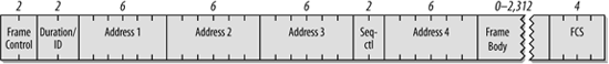
802.11 MAC frames do not include some of the classic Ethernet frame features, most notably the type/length field and the preamble. The preamble is part of the physical layer, and encapsulation details such as type and length are present in the header on the data carried in the 802.11 frame.
Frame Control
Each frame starts with a two-byte Frame Control subfield, shown in Figure 3-10. The components of the Frame Control subfield are:
Protocol version
Two bits indicate which version of the 802.11 MAC is contained in the rest of the frame. At present, only one version of the 802.11 MAC has been developed; it is assigned the protocol number 0. Other values will appear when the IEEE standardizes changes to the MAC that render it incompatible with the initial specification. So far, none of the revisions to 802.11 have required incrementing the protocol number.
Type and subtype fields
Type and subtype fields identify the type of frame used. To cope with noise and unreliability, a number of management functions are incorporated into the 802.11 MAC. Some, such as the RTS/CTS operations and the acknowledgments, have already been discussed. Table 3-1 shows how the type and subtype identifiers are used to create the different classes of frames.
Figure 3-10. Frame control field
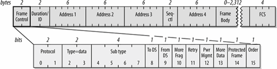
In Table 3-1, bit strings are written most-significant bit first, which is the reverse of the order used in Figure 3-10. Therefore, the frame type is the third bit in the frame control field followed by the second bit (b3 b2), and the subtype is the seventh bit, followed by the sixth, fifth, and fourth bits (b7 b6 b5 b4).
|
Subtype value |
Subtype name |
|---|---|
|
Management frames (type=00)a |
|
|
0000 |
Association request |
|
0001 |
Association response |
|
0010 |
Reassociation request |
|
0011 |
Reassociation response |
|
0100 |
Probe request |
|
0101 |
Probe response |
|
1000 |
Beacon |
|
1001 |
Announcement traffic indication message (ATIM) |
|
1010 |
Disassociation |
|
1011 |
Authentication |
|
1100 |
Deauthentication |
|
1101 |
Action (for spectrum management with 802.11h, also for QoS) |
|
Control frames (type=01)b |
|
|
1000 |
Block Acknowledgment Request (QoS) |
|
1001 |
Block Acknowledgment (QoS) |
|
1010 |
Power Save (PS)-Poll |
|
1011 |
RTS |
|
1100 |
CTS |
|
1101 |
Acknowledgment (ACK) |
|
1110 |
Contention-Free (CF)-End |
|
1111 |
CF-End+CF-Ack |
|
Data frames (type=10) |
|
|
0000 |
Data |
|
0001 |
Data+CF-Ack |
|
0010 |
Data+CF-Poll |
|
0011 |
Data+CF-Ack+CF-Poll |
|
0100 |
Null data (no data transmitted) |
|
0101 |
CF-Ack (no data transmitted) |
|
0110 |
CF-Poll (no data transmitted) |
|
0111 |
CF-Ack+CF-Poll (no data transmitted) |
|
1000 |
QoS Datac |
|
1001 |
QoS Data + CF-Ackc |
|
1010 |
QoS Data + CF-Pollc |
|
1011 |
QoS Data + CF-Ack + CF-Pollc |
|
1100 |
QoS Null (no data transmitted)c |
|
1101 |
QoS CF-Ack (no data transmitted)c |
|
1110 |
QoS CF-Poll (no data transmitted)c |
|
1111 |
QoS CF-Ack+CF-Poll (no data transmitted)c |
|
(Frame type 11 is reserved) |
|
|
a Management subtypes 0110-0111 and 1110-1111 are reserved and not currently used. |
|
|
b Control subtypes 0000-0111 are reserved and not currently used. |
|
|
c Proposed by the 802.11e task group, but not yet standardized. Note that these frames all have a leading one, which has caused some to refer to the first bit as the QoS bit. |
|
ToDS and FromDS bits
These bits indicate whether a frame is destined for the distribution system. All frames on infrastructure networks will have one of the distribution system bits set. Table 3-2 shows how these bits are interpreted. As Chapter 4 will explain, the interpretation of the address fields depends on the setting of these bits.
|
To DS=0 |
To DS=1 |
|
|---|---|---|
|
From DS=0 |
All management and control frames Data frames within an IBSS (never infrastructure data frames) |
Data frames transmitted from a wireless station in an infrastructure network. |
|
From DS=1 |
Data frames received for a wireless station in an infrastructure network |
Data frames on a "wireless bridge" |
More fragments bit
This bit functions much like the "more fragments" bit in IP. When a higher-level packet has been fragmented by the MAC, the initial fragment and any following nonfinal fragments set this bit to 1. Large data frames and some management frames may be large enough to require fragmentation; all other frames set this bit to 0. In practice, most data frames are transmitted at the maximum Ethernet size and fragmentation is not often used.
Retry bit
From time to time, frames may be retransmitted. Any retransmitted frames set this bit to 1 to aid the receiving station in eliminating duplicate frames.
Power management bit
Network adapters built on 802.11 are often built to the PC Card form factor and used in battery-powered laptop or handheld computers. To conserve battery life, many small devices have the ability to power down parts of the network interface. This bit indicates whether the sender will be in a powersaving mode after the completion of the current atomic frame exchange. 1 indicates that the station will be in powersave mode, and 0 indicates that the station will be active. Access points perform a number of important management functions and are not allowed to save power, so this bit is always 0 in frames transmitted by an access point.
More data bit
To accommodate stations in a powersaving mode, access points may buffer frames received from the distribution system. An access point sets this bit to indicate that at least one frame is available and is addressed to a dozing station.
Protected Frame bit
Wireless transmissions are inherently easier to intercept than transmissions on a fixed network. If the frame is protected by link layer security protocols, this bit is set to 1, and the frame changes slightly. The Protected Frame bit was previously called the WEP bit.
Order bit
Frames and fragments can be transmitted in order at the cost of additional processing by both the sending and receiving MACs. When the "strict ordering" delivery is employed, this bit is set to 1.
Duration/ID Field
The Duration/ID field follows the frame control field. This field has several uses and takes one of the three forms shown in Figure 3-11.
Figure 3-11. Duration/ID field
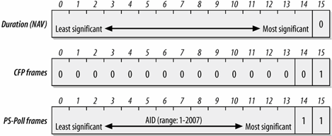
Duration: setting the NAV
When bit 15 is 0, the duration/ID field is used to set the NAV. The value represents the number of microseconds that the medium is expected to remain busy for the transmission currently in progress. All stations must monitor the headers of all frames they receive and update the NAV accordingly. Any value that extends the amount of time the medium is busy updates the NAV and blocks access to the medium for additional time.
Frames transmitted during contention-free periods
During the contention-free periods, bit 14 is 0 and bit 15 is 1. All other bits are 0, so the duration/ID field takes a value of 32,768. This value is interpreted as a NAV. It allows any stations that did not receive the Beacon[*] announcing the contention-free period to update the NAV with a suitably large value to avoid interfering with contention-free transmissions.
[*] Beacon frames are a subtype of management frames, which is why "Beacon" is capitalized.
PS-Poll frames
Bits 14 and 15 are both set to 1 in PS-Poll frames. Mobile stations may elect to save battery power by turning off antennas. Dozing stations must wake up periodically. To ensure that no frames are lost, stations awaking from their slumber transmit a PS-Poll frame to retrieve any buffered frames from the access point. Along with this request, waking stations incorporate the association ID (AID) that indicates which BSS they belong to. The AID is included in the PS-Poll frame and may range from 1-2,007. Values from 2,008-16,383 are reserved and not used.
Address Fields
An 802.11 frame may contain up to four address fields. The address fields are numbered because different fields are used for different purposes depending on the frame type (details are found in Chapter 4). The general rule of thumb is that Address 1 is used for the receiver, Address 2 for the transmitter, and Address 3 field for filtering by the receiver. In an infrastructure network, for example, the third address field is used by the receiver to determine whether the frame is part of the network it is associated to.[*]
[*] 802.11 specifies that stations should ignore frames that do not have the same BSSID, but most products do not correctly implement BSSID filtering and will pass any received frame up to higher protocol layers.
Addressing in 802.11 follows the conventions used for the other IEEE 802 networks, including Ethernet. Addresses are 48 bits long. If the first bit sent to the physical medium is a 0, the address represents a single station (unicast). When the first bit is a 1, the address represents a group of physical stations and is called a multicast (or group) address. If all bits are 1s, then the frame is a broadcast and is delivered to all stations connected to the wireless medium.
48-bit addresses are used for a variety of purposes:
Destination address
As in Ethernet, the destination address is the 48-bit IEEE MAC identifier that corresponds to the final recipient: the station that will hand the frame to higher protocol layers for processing.
Source address
This is the 48-bit IEEE MAC identifier that identifies the source of the transmission. Only one station can be the source of a frame, so the Individual/Group bit is always 0 to indicate an individual station.
Receiver address
This is a 48-bit IEEE MAC identifier that indicates which wireless station should process the frame. If it is a wireless station, the receiver address is the destination address. For frames destined to a node on an Ethernet connected to an access point, the receiver is the wireless interface in the access point, and the destination address may be a router attached to the Ethernet.
Transmitter address
This is a 48-bit IEEE MAC address to identify the wireless interface that transmitted the frame onto the wireless medium. The transmitter address is used only in wireless bridging.
Basic Service Set ID (BSSID)
To identify different wireless LANs in the same area, stations may be assigned to a BSS. In infrastructure networks, the BSSID is the MAC address used by the wireless interface in the access point. Ad hoc networks generate a random BSSID with the Universal/Local bit set to 1 to prevent conflicts with officially assigned MAC addresses.
The number of address fields used depends on the type of frame. Most data frames use three fields for source, destination, and BSSID. The number and arrangement of address fields in a data frame depends on how the frame is traveling relative to the distribution system. Most transmissions use three addresses, which is why only three of the four addresses are contiguous in the frame format.
Sequence Control Field
This 16-bit field is used for both defragmentation and discarding duplicate frames. It is composed of a 4-bit fragment number field and a 12-bit sequence number field, as shown in Figure 3-12. Sequence numbers are not used in control frames, so the Sequence Control field is not present.
Figure 3-12. Sequence Control field
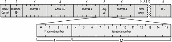
Higher-level frames are each given a sequence number as they are passed to the MAC for transmission. The sequence number subfield operates as a modulo-4096 counter of the frames transmitted. It begins at 0 and increments by 1 for each higher-level packet handled by the MAC. If higher-level packets are fragmented, all fragments will have the same sequence number. When frames are retransmitted, the sequence number is not changed.
What differs between fragments is the fragment number. The first fragment is given a fragment number of 0. Each successive fragment increments the fragment number by 1. Retransmitted fragments keep their original sequence numbers to assist in reassembly.
Stations that implement the QoS extensions use a slightly different interpretation of the sequence control field because multiple transmit queues need to be maintained.
Frame Body
The frame body, also called the Data field, moves the higher-layer payload from station to station. As originally specified, 802.11 can transmit frames with a maximum payload of 2,304 bytes of higher-level data. Implementations must support larger frame bodies to accommodate additional headers for security and QoS. 802.2 LLC headers use 8 bytes for a maximum network protocol payload of 2,296 bytes. Preventing fragmentation must be done at the protocol layer. On IP networks, Path MTU Discovery (RFC 1191) will prevent the transmission of frames with Data fields larger than 1,500 bytes.
802.11 differs from other link layer technologies in two notable ways. First, there is no higher-level protocol tag in the 802.11 frame to distinguish between higher-layer protocol types. Higher-level protocols are tagged with a type field by an additional header, which is used as the start of the 802.11 payload. Second, 802.11 does not generally pad frames to a minimum length. Many frames used by 802.11 are short, and the chips and electronics used in network interfaces has progressed to the point where a pad is no longer necessary.
Frame Check Sequence
As with Ethernet, the 802.11 frame closes with a frame check sequence (FCS). The FCS is often referred to as the cyclic redundancy check (CRC) because of the underlying mathematical operations. The FCS allows stations to check the integrity of received frames. All fields in the MAC header and the body of the frame are included in the FCS. Although 802.3 and 802.11 use the same method to calculate the FCS, the MAC header used in 802.11 is different from the header used in 802.3, so the FCS must be recalculated by access points.
When frames are sent to the wireless interface, the FCS is calculated before those frames are sent out over the wireless link. Receivers can then calculate the FCS from the received frame and compare it to the received FCS. If the two match, there is a high probability that the frame was not damaged in transit.
On Ethernets, frames with a bad FCS are simply discarded, and frames with a good FCS are passed up the protocol stack. On 802.11 networks, frames that pass the integrity check may also require the receiver to send an acknowledgment. For example, data frames that are received correctly must be positively acknowledged, or they are retransmitted. 802.11 does not have a negative acknowledgment for frames that fail the FCS; stations must wait for the acknowledgment timeout before retransmitting.
Introduction to Wireless Networking
- Introduction to Wireless Networking
- Why Wireless?
- What Makes Wireless Networks Different
- A Network by Any Other Name...
Overview of 802.11 Networks
- Overview of 802.11 Networks
- IEEE 802 Network Technology Family Tree
- 11 Nomenclature and Design
- 11 Network Operations
- Mobility Support
11 MAC Fundamentals
- 11 MAC Fundamentals
- Challenges for the MAC
- MAC Access Modes and Timing
- Contention-Based Access Using the DCF
- Fragmentation and Reassembly
- Frame Format
- Encapsulation of Higher-Layer Protocols Within 802.11
- Contention-Based Data Service
- Frame Processing and Bridging
11 Framing in Detail
- 11 Framing in Detail
- Data Frames
- Control Frames
- Management Frames
- Frame Transmission and Association and Authentication States
Wired Equivalent Privacy (WEP)
- Wired Equivalent Privacy (WEP)
- Cryptographic Background to WEP
- WEP Cryptographic Operations
- Problems with WEP
- Dynamic WEP
User Authentication with 802.1X
- User Authentication with 802.1X
- The Extensible Authentication Protocol
- EAP Methods
- 1X: Network Port Authentication
- 1X on Wireless LANs
11i: Robust Security Networks, TKIP, and CCMP
- 11i: Robust Security Networks, TKIP, and CCMP
- The Temporal Key Integrity Protocol (TKIP)
- Counter Mode with CBC-MAC (CCMP)
- Robust Security Network (RSN) Operations
Management Operations
- Management Operations
- Management Architecture
- Scanning
- Authentication
- Preauthentication
- Association
- Power Conservation
- Timer Synchronization
- Spectrum Management
Contention-Free Service with the PCF
- Contention-Free Service with the PCF
- Contention-Free Access Using the PCF
- Detailed PCF Framing
- Power Management and the PCF
Physical Layer Overview
- Physical Layer Overview
- Physical-Layer Architecture
- The Radio Link
- RF Propagation with 802.11
- RF Engineering for 802.11
The Frequency-Hopping (FH) PHY
- The Frequency-Hopping (FH) PHY
- Frequency-Hopping Transmission
- Gaussian Frequency Shift Keying (GFSK)
- FH PHY Convergence Procedure (PLCP)
- Frequency-Hopping PMD Sublayer
- Characteristics of the FH PHY
The Direct Sequence PHYs: DSSS and HR/DSSS (802.11b)
- The Direct Sequence PHYs: DSSS and HR/DSSS (802.11b)
- Direct Sequence Transmission
- Differential Phase Shift Keying (DPSK)
- The Original Direct Sequence PHY
- Complementary Code Keying
- High Rate Direct Sequence PHY
11a and 802.11j: 5-GHz OFDM PHY
- 11a and 802.11j: 5-GHz OFDM PHY
- Orthogonal Frequency Division Multiplexing (OFDM)
- OFDM as Applied by 802.11a
- OFDM PLCP
- OFDM PMD
- Characteristics of the OFDM PHY
11g: The Extended-Rate PHY (ERP)
- 11g: The Extended-Rate PHY (ERP)
- 11g Components
- ERP Physical Layer Convergence (PLCP)
- ERP Physical Medium Dependent (PMD) Layer
A Peek Ahead at 802.11n: MIMO-OFDM
11 Hardware
- 11 Hardware
- General Structure of an 802.11 Interface
- Implementation-Specific Behavior
- Reading the Specification Sheet
Using 802.11 on Windows
11 on the Macintosh
Using 802.11 on Linux
- Using 802.11 on Linux
- PCMCIA Support on Linux
- Linux Wireless Extensions and Tools
- Agere (Lucent) Orinoco
- Atheros-Based cards and MADwifi
- 1X on Linux with xsupplicant
Using 802.11 Access Points
- Using 802.11 Access Points
- General Functions of an Access Point
- Power over Ethernet (PoE)
- Selecting Access Points
- Cisco 1200 Access Point
- Apple AirPort
Logical Wireless Network Architecture
- Logical Wireless Network Architecture
- Evaluating a Logical Architecture
- Topology Examples
- Choosing Your Logical Architecture
Security Architecture
- Security Architecture
- Security Definition and Analysis
- Authentication and Access Control
- Ensuring Secrecy Through Encryption
- Selecting Security Protocols
- Rogue Access Points
Site Planning and Project Management
- Site Planning and Project Management
- Project Planning and Requirements
- Network Requirements
- Physical Layer Selection and Design
- Planning Access-Point Placement
- Using Antennas to Tailor Coverage
11 Network Analysis
11 Performance Tuning
Conclusions and Predictions
EAN: 2147483647
Pages: 179
