Cisco CallManager Feature List
The following features are available in CallManager release 4.1:
- Abbreviated Dialing (AbbrDial)
- Annunciator
- Answer/Release
- Application Programming Interfaces (API)
Call Detail Records (CDR) and Call Management Records (CMR) API
Computer Telephony Integration (CTI) API
AXL SOAP Database API
LDAP Directory Integration API
IP Phone Services API
- Audible Indicator of Ringing Phone
- Authentication/Encryption
- Auto Answer/Intercom
- Automated Alternate Routing (AAR)
- Automated Change Notification/Database Replication
- Automated Installation and Recovery
- Automated Systemwide Software and Feature Upgrades
- Automatic Attenuation/Gain Adjustment
- Automatic Bandwidth Selection
- Automatic Number Identification (ANI)
- Auto-Registration
- Backup and Restore System (BARS)
- Barge/Conference Barge (cBarge)
- Broadcast Paging Support (with third-party integration)
- Bulk Administration Tool (BAT)
- Call Admission Control (CAC)
- Call Back
- Call Connection
- Call Coverage
- Call Detail Records (CDR) and Call Management Records (CMR)
- Call Forwarding
- Call Forwarding Support for Third-Party Applications
- Call Park
- Call Pickup/Group Call Pickup (PickUp/GPickUp)
- Call Preservation for Active Calls During CallManager Server Outage
- Call Status per Line
- Call Waiting/Retrieve
- Calling Line Identification (CLID or Caller ID)
- Calling Line ID Restriction (CLIR) on a Per-Call Basis
- Calling Party Name Identification (CNID)
- Calling Party Display Restriction
- Certificate Authority Proxy Function (CAPF) Report Generation
- CDR Analysis and Reporting (CAR) Tool (formerly Administrative Reporting Tool)
- Centralized System Administration, Monitoring, and Reporting
- Cisco ATA-186 2-Port Analog Gateway Support
- Cisco Bulk Trace Analysis
- Cisco CallManager Administration Enhancements for Large System Administration
- Cisco CallManager Attendant Console (formerly Cisco WebAttendant)
- Cisco CallManager Serviceability
- Cisco CallManager Trace Collection Tool
- Cisco CallManager User Options Web Page
- Cisco Conference Connection (CCC) Support
- Cisco CTL Client
- Cisco Discovery Protocol (CDP) Support
- Cisco Emergency Responder (CER) Support
- Cisco IP Manager-Assistant
- Cisco IP Phones 7971, 7970, 7961, 7960, 7941, 7940, Conference Stations 7936 and 7935, Wireless 7920, Expansion Module 7914, 7912,7905, and 7902 Support
- Cisco IP Phone Services
- Cisco IP Software-Based Phone Support (IP SoftPhone and IP Communicator)
- Cisco Personal Address Book
- Cisco VG248 48-Port Analog Gateway Support
- CISCO-CCM-MIB
- Click to Dial/Click to Call
- Client Matter Codes
- Codec Support (Audio and Video)
- Closest Match Routing
- Clustering
- Computer Telephony Integration (CTI) Support
- Conference/Confrn
- Context-Sensitive Help
- Contrast/LCD Contrast
- CTI Redundancy with CTIManager
- Date/Time Zone Display Format Configurable per Phone
- Dependency Records
- Device Type-Based Information and Resets
- Device Downloadable Feature Upgrade
- Device Pool
- Device Search in Cisco CallManager Administration
- Device Wizard
- DHCP IP Assignment for Phones and Gateways
- Dial Plan Partitions and Calling Search Spaces
- Dialed Number Analyzer (DNA)
- Dialed Number Translation Table (Inbound and Outbound Translation)
- Dialed Number Identification Service (DNIS) and RDNIS
- Digit Analysis and Translation (Calling Party Number and Called Party Number)
- Digital Signal Processor (DSP) Resource Management
- Direct Inward Dial
- Direct Outward Dial
- Direct Transfer (DirTrfr)
- Directories Button on Cisco IP Phones
- Directory Dial from Cisco IP Phones
- Distinctive RingInternal Versus External
- Distinctive Ring Selection
- Distributed CallManager Server Architecture
- Distributed and Topologically Aware Resource Sharing
- DSP Resource Alignment
- Dual Tone Multi-Frequency (DTMF) Support
- Embedded Directory for User Data
- Emergency 911 Service (E911) Support
- EndCall
- Extension Mobility
- External Route Plan Wizard
- External/Internal Trunk Designation
- Failover
- FAX/Modem over IP Support
- Forced Authorization Codes
- FXO and FXS Support
- Group Call Pickup/GPickUp
- H.323 Client, Gateway, and Gatekeeper Support
- Hold/Resume
- HTTP Server Support
- Hunt Lists and Line Groups
- Inline Power Support on Cisco IP Phones
- Internationalization/Localization
- ISDN Basic Rate Interface (BRI) Support
- Join
- JTAPI Computer Telephony Interface (CTI)
- JTAPI Control of Analog (FXS) Gateway Ports
- LDAPv3 Directory Interface
- Least Cost Routing (LCR) Support
- Lightweight Directory Access Protocol (LDAP) Support
- Line
- Manager Assistant Services
- Mappable Softkeys
- Media Gateway Control Protocol (MGCP) Support
- Media Resource Group List Support
- Meet-Me Conference/MeetMe
- Messages Button on Cisco IP Phones
- Message Waiting Indicator
- Microsoft NetMeeting
- Multilevel Administration
- Multi-Level Precedence and Preemption (MLPP)
- Multiple Calls per Line
- Multiple Line Appearances per Phone
- Music on Hold
- Mute
- NewCall
- North American Numbering Plan (NANP) and Non-NANP Support
- Off-Premise Extension (OPX) Support
- On-Hook and Off-Hook Dialing
- Overlap Sending/Receiving
- Paperless Phone
- Performance Monitoring and Alarms
- Privacy
- Private Line Auto RingDown (PLAR) Support
- QSIG Support
- Quality of Service (QoS)
- Quality Reporting Tool (QRT)
- Redial/REDL
- Redirected Number Identification Service (RDNIS)
- Redundancy/Failover
- Remote Site Survivability for MGCP Gateways
- Scalability Enhancements through H.323 Gatekeeper (Beyond Ten Sites)
- Serviceability Enhancements Through SNMP, CDP, CiscoWorks
- Service URLs on Line Buttons
- Services on XML-Capable Cisco IP Phones
- Settings Button on Cisco IP Phones
- Single CDR Repository per CallManager Cluster
- Single Point for System/Device Configuration
- Simple Network Management Protocol (SNMP) Support
- Speakerphone/SPKR
- Speed Dial
- Supplementary Services
- Survivable Remote Site Telephony (SRST)
- Syslog Support for Debugging Output
- System Event Reporting
- T1/E1 PRI Support
- T1/E1-CAS Support
- Telephony Application Programming Interface (TAPI) and JTAPI Support
- Time of Day Routing
- Time Zone Configuration
- Toll Restriction/Toll Fraud Prevention
- Tone on Hold
- Tool for Auto-Registered Phone Support (TAPS)
- Transcoding and Media Termination Point (MTP) Support
- Transfer/XFER/Transf...
- Trivial File Transfer Protocol (TFTP) Support
- Turn off Phone Display
- Unicast Conference
- Video Telephony Support
- Virus Protection Certification
- Visual Indicator of Ringing Phone
- Voice Activity Detection (VAD)/Silence Suppression Support
- Voice Mail Support
- Volume Controls
- XML Support
- Zero Cost Automated Phone Adds and Moves
Abbreviated Dialing (AbbrDial)
Note
This feature was introduced in CallManager release 4.0.
Abbreviated dialing enables users to quickly access up to 99 preconfigured speed dial numbers that they have associated with index numbers. While the phone is on-hook, users can dial an index number, 01 through 99, and then press the AbbrDial softkey to dial the phone number associated with the index number. Users define their speed dials via the Cisco CallManager User Options web page or via the MyFastDials XML service on the phone.
Annunciator
Note
This feature was introduced in CallManager release 4.0.
The Cisco IP Voice Media Streaming App service, which also offers Music on Hold, software-based (G.711 only) conferencing, and software-based (G.711 only) media termination point (MTP) functions, has been enhanced in CallManager release 4.0(1) to include the capability to play prerecorded announcements (.wav files) and tones to Cisco IP Phones, gateways, and other configurable devices. The annunciator capability enables CallManager to audibly alert callers with the reason that a call has failed. Annunciator can also play tones for some transferred calls (ringback tones) and some conference scenarios (party joining/departing tones).
Table A-1 provides information about the CallManager annunciator service parameter that you can access on the Service Parameters Configuration page (Service > Service Parameters > select a server > Cisco CallManager) in CallManager Administration.
|
Service Parameter |
Default |
Valid Value |
|---|---|---|
|
Duplex Streaming Enabled Determines whether Music on Hold (MOH) and annunciator use duplex streaming. True means that MOH and annunciator use duplex (two-way) streaming; False means that MOH and annunciator use simplex (one-way) streaming. Specifying True facilitates interoperability with certain firewalls and routers configured for Network Address Translation (NAT). |
False |
True or False |
Table A-2 provides information about Cisco IP Voice Media Streaming App annunciator service parameters that you can access on the Service Parameters Configuration page (Service > Service Parameters > select a server > Cisco IP Voice Media Streaming App).
|
Service Parameter |
Default |
Valid Values |
|---|---|---|
|
Call Count Specifies the maximum number of simultaneous announcements that the annunciator supports. Increasing this value above the recommended default of 48 might cause performance degradation on a CallManager that is running on the same server. If you need to increase this value above the default, consider installing the Cisco IP Voice Media Streaming App service on a separate server. |
48 |
0 to 400 |
|
Run Flag This service parameter determines whether the annunciator functionality is enabled. |
True |
True or False |
Answer/Release
Answer/Release is used in conjunction with a headset and is available for all Cisco IP Phones that can use a headset and display softkeys. The following sections describe how Answer/Release works for each Cisco IP Phone.
Answer/Release on Cisco IP Phone Series 79xx
Answer is a softkey used to answer a ringing line. To release a call, you can press EndCall or toggle the HEADSET button on the phone if you're using a headset. On Cisco IP Phone series 79xx, the Answer and Resume softkeys are automatically available.
Answer/Release on Cisco IP Phones 12SP+ and 30VIP
Answer/Release is used in conjunction with a headset, so the user can press a button on the headset apparatus to answer and release (disconnect) calls. The phone's handset must be off-hook to use Answer/Release.
Answer/Release can be configured on the button template for Cisco IP Phones 12SP+ or 30VIP. To answer a call when using a headset, the user presses the Answer/Release button and is connected to the caller. To disconnect, the user presses the Answer/Release button again.
Application Programming Interfaces (API)
CallManager exposes many of its databases, directories, and telephony interfaces through APIs. In addition, developers can write applications to deploy sophisticated IP Communications applications through CallManager's support for open standards such as XML and TAPI/JTAPI.
You can find documentation on these APIs at the Cisco AVVID Developer Support Central website at the following link:
http://www.cisco.com/pcgi-bin/dev_support/access_level/product_support
Call Detail Records (CDR) and Call Management Records (CMR) API
CallManager releases 3.2 and earlier use a Microsoft SQL Server 7.0 database. CallManager releases 3.3 and later use Microsoft SQL 2000. Call accounting and billing applications can query the CDR tables via ODBC calls, direct SQL queries to the database, or via Microsoft ActiveX Data Objects (ADO). Read-only access is provided to all tables in the database; access to the CDR and CMR tables is read/write.
Computer Telephony Integration (CTI) API
CallManager exposes sophisticated control of many aspects of the complete Cisco IP Communications telephony platform via its Computer Telephony Integration (CTI) APIs. These APIs enable custom applications to register interest in CallManager device call events and take full control of those devices to make, take, transfer, bridge, join, or end calls. Applications can monitor or control Cisco IP Phones, create and register software-based phone ports (CTI ports) that provide media streaming capabilities, and manage CTI route points to queue and distribute high-volume incoming calls. The section "Computer Telephony Integration (CTI) Support" provides more information.
AXL SOAP Database API
The AVVID XML Layer (AXL) API provides a mechanism for inserting, retrieving, updating, and removing data from the CallManager SQL database using an Extensible Markup Language (XML) Simple Object Access Protocol (SOAP) interface.
The AXL SOAP API provides application developers with direct access to the CallManager database and allows them to add, remove, update, and retrieve phones, lines, users, device profiles, route plan information (route patterns, translation patterns, calling search spaces, partitions), login, logout, device resets, and more.
LDAP Directory Integration API
CallManager provides an embedded Lightweight Directory Access Protocol (LDAP)-compliant directory for storing user and device profiles, user preferences, passwords and PINs, and other information. The API provides a method for integrating the CallManager embedded directory into external directories such as Microsoft Active Directory and iPlanet Netscape Directory Server to take advantage of an enterprise's existing LDAP directory infrastructure.
IP Phone Services API
XML-capable Cisco IP Phones provide support for accessing and displaying XML-formatted web content and applications developed by customers or third-party integrators. The API provides details and examples for developers to use in creating their own applications.
See the section "XML Support" for more details.
Audible Indicator of Ringing Phone
All Cisco IP Phones provide configurable audible notification of an incoming call on a per-line basis. Cisco IP Phones 79xx provide the option to ring, beep, or have audible notification disabled. You can configure the type of indication (audible and visual, see the later section "Visual Indicator of Ringing Phone" for more information) using the following service parameters:
- Ring Setting of Busy Station Policy
- Ring Setting of Busy Station
- Ring Setting of Idle Station
You can access these service parameters in CallManager Administration (Service > Service Parameters > select a server > Cisco CallManager). Users can configure notification on the Cisco CallManager User Options web page (choose the link to Configure the Ring Settings for Your Phone).
Authentication/Encryption
Cisco IP Communications comprises numerous security mechanisms for authenticating, and in some cases encrypting, administrative access, user access, device signaling, and media. This appendix discusses the following areas:
- Administrative access to CallManager
- Device (that is, phones, gateways, and other devices) authentication, signaling, and media encryption
The Cisco Press book, Cisco CallManager Best Practices (ISBN: 1-58705-139-7) offers an excellent chapter on security.
CallManager Administration Web Page Authentication
CallManager Administration and CallManager Serviceability web pages utilize the integrated authentication scheme of Microsoft Internet Information Server (IIS) by default (that is, when Multilevel Administration [MLA] is not enabled). Users who are defined in the Windows 2000 Administrators group are granted access to the CallManager Administration and CallManager Serviceability web pages.
Multilevel Administration
CallManager release 3.2 introduced a new feature called Multilevel Administration (MLA). When MLA is enabled, the usernames and passwords of administrators are authenticated via LDAP rather than via Microsoft IIS Integrated Password Authentication. The LDAP directory used for administrative access can be the embedded directory provided during CallManager installation, or an external LDAP-compliant directory such as Microsoft Active Directory or Netscape Directory Services. See the section "Lightweight Directory Access Protocol (LDAP) Support" for more information.
Note
MLA was enhanced in CallManager release 4.1.
As of CallManager release 4.1, MLA supports UMX APIs for LDAP directory access. Prior to this enhancement, custom Java-based code implemented directory access. Release 4.1 removes the dependency on Microsoft Java (JVM).
Cisco CallManager User Options Web Page Authentication
The username and password used to access the Cisco CallManager User Options web page is authenticated via LDAP. The LDAP directory used to authenticate connections to this web page can be the embedded directory provided during CallManager installation, or an external LDAP-compliant directory such as Microsoft Active Directory or Netscape Directory Services. The section "Lightweight Directory Access Protocol (LDAP) Support" provides more information.
CallManager Web Page Encryption (HTTPS)
Note
This feature was introduced in CallManager release 4.1(2).
CallManager release 4.1(2) changes most (not all) web page directories to Hypertext Transfer Protocol Secure (HTTPS). To maintain backward compatibility with some third-party applications and XML services, some web directories continue to use nonencrypted HTTP with the intent that as those applications also migrate to HTTPS. Future releases of CallManager will force the use of HTTPS on all virtual directories. The digital certificates used by the IIS and Tomcat web servers are created automatically during installation and are self-signed. You can also update these certificates to use root-signed certificates. For CallManager release 4.1(2), the following virtual directories have been modified to force the use of HTTPS:
- CallManager Administration (CCMAdmin)
- CallManager Serviceability (CCMService)
- Cisco CallManager User Options (CCMUser)
Some examples of directories that have not moved to HTTPS are as follows:
- XML service directories (extension mobility, Quality Reporting Tool [QRT], call back)
- AXL SOAP API
LDAP over SSL (LDAPS) Support
Note
This feature was introduced in CallManager release 4.1(2).
Secure Sockets Layer (SSL) encrypt the communication between the web server and the LDAP server (used when authenticating user access to CallManager Administration, CallManager Serviceability, and Cisco CallManager User Options web pages). The embedded directory is automatically configured to use SSL during installation, and support is also provided for using SSL if integrated with an external LDAP-compliant directory such as Microsoft Active Directory or Netscape Directory Services.
Extension Mobility Username/PIN Authentication
Users are prompted to enter their username and PIN when accessing the extension mobility login service (for more information, see the section "Extension Mobility"). These usernames and PINs are transported over HTTP and authenticated via LDAP. The LDAP directory used for storing these usernames and PINs can be the embedded directory provided during CallManager installation or an external LDAP-compliant directory such as Microsoft Active Directory or Netscape Directory Services. See the section "Lightweight Directory Access Protocol (LDAP) Support" for more information.
SQL Database Access Authentication
Applications attempting to gain access to the CallManager SQL database via ODBC, ADA, or SOAP APIs are given access based on the authentication method configured in SQL Server. CallManager releases prior to 4.0(1) use SQL authentication while CallManager releases 4.0(1) and later use Windows Integrated Authentication. See the "Call Detail Records (CDR) and Call Management Records (CMR) API" and "Database API" sections for more details.
TFTP Directory Access Restrictions
The Cisco TFTP service is an integrated service that is installed and configured automatically during CallManager installation, and is tightly synchronized with the database of the cluster so that changes to devices made in CallManager Administration are automatically propagated through the Database Layer and into the individualized configuration files in the TFTP directory (C:Program FilesCiscoTFTPPath). The TFTP service is configured to allow only read-only requests from clients (read/write permissions are permitted only through the Database Layer), and the directory cannot be browsed (meaning the TFTP request must specify the exact filename). See the section "Trivial File Transfer Protocol (TFTP) Support" for more details.
Phone File Authentication
Note
This feature was enhanced in CallManager release 4.0(1).
File authentication prevents tampering with the files that the phone retrieves from the TFTP server, such as the firmware load, configuration files, and so on, prior to loading them on the phone. CallManager release 3.3(4) introduced signed binary firmware images only. Configuration files are still unsigned in this release. Tampering with the file will be detected by the phone, causing it to reject the file. After a signed firmware image has been loaded onto the phone, the phone will never accept an unsigned image again, eliminating the risk of a hacker working around this security measure by loading an older phone firmware image into the phone. File authentication is supported on Cisco IP Phones 7902, 7905, 7910, 7912, 7940, 7941, 7960, 7961, 7970, and 7971.
CallManager release 4.0(1) extended the use of signed files to also include configuration files, ringlists, locale files, and Certificate Trust List (CTL) files.
Device Authentication
Note
This feature was introduced in CallManager release 4.0(1).
Device authentication is composed of several components that work together to establish a mutual authentication between the IP Phone and CallManager:
- Each CallManager server has an x.509v3 certificate created and stored on its hard disk.
- On Cisco IP Phones 7940, 7941, 7960, 7961, 7970, and 7971, an x.509v3 digital certificate is also downloaded and stored in non-volatile random-access memory (NVRAM).
- A Certificate Trust List (CTL) file (CTLFile.tlv) is created and stored in the TFTP server, and is downloaded by the phones. This CTL file contains the list of known servers so that the phones have a list of legitimate, trusted hosts to which they can communicate.
- With all three of the preceding items in place, the phones use SSL to create a mutually authenticated TCP session over which to transmit all signaling messages.
Support is also extended to Cisco Unity voice mail and Cisco IOS voice gateways. Like the phones, Unity uses a self-signed or root-signed certificate and SSL to create a mutually authenticated TCP session over which to communicate with CallManager. Cisco IOS voice gateways also use self-signed or root-signed certificates, but manually configured IPSec tunnels instead of SSL. These IPSec tunnels are used to carry all MGCP, H.323, or SIP signaling messages between CallManager and the gateway. IPSec tunnels are configured either directly in each CallManager server, or a separate IPSec concentrator (such as a Cisco IOS router, PIX Firewall, or 3000 series VPN concentrator) can be used to front end the CallManager servers and offload the burden of managing large numbers of IPSec connections.
Signaling Encryption
Note
This feature was introduced in CallManager release 4.0(1) and enhanced in CallManager release 4.1(2).
Leveraging the device authentication mechanisms described in the preceding section, "Device Authentication," all signaling messages transmitted over the SSL connection between the IP phone and CallManager can optionally be encrypted using Advanced Encryption Standard (AES) 128-bit encryption. CallManager Administration makes this optional to provide you with granular choices of how secure you want the network to be. Encrypting the signaling makes it more difficult to capture and troubleshoot with a sniffer, for example, so you have the option of configuring the phone for authentication only or for encryption. When the phone is set to encrypted mode, the media is also automatically encrypted (meaning you cannot configure the phone to encrypt only its signaling but not its media), and media encryption requires that the signaling also be encrypted (you cannot encrypt your media without first encrypting the signaling).
In the case of Cisco IOS voice gateways, the IPSec configuration determines what encryption algorithm will be used for the signaling channel. Cipher support varies by the platform and IOS version deployed. Most support Triple Data Encryption Standard (3DES), which is 168-bit encryption; some platforms also support AES-128 and AES-256.
CallManager release 4.1(2) extends support for signaling and media encryption to Cisco IP Phones 7940, 7941, 7960, and 7961. Prior to this release, these models supported device authentication only, but not encryption. CallManager security is implemented through authentication and encryption. CallManager provides enterprise parameters (described in Table A-3) and service parameters (described in Table A-4) to control certain security settings. Table A-3 provides information about security-related enterprise parameters (System > Enterprise Parameters).
|
Enterprise Parameter |
Default |
Valid Values |
|---|---|---|
|
Device Security Mode Determines whether security is provided for devices that have been configured as Use System Default in the Device Security Mode field on the Phone Configuration page in CallManager Administration. If you configure encryption for Cisco IP Phones that support barge or cBarge, those encrypted devices cannot accept barge requests when they are participating in an encrypted call. When the call is encrypted, the barge attempt fails. See the section "Barge/Conference" for more information. |
Non Secure |
Non Secure (no device authentication, signaling authentication, or encryption) Authenticated (only device authentication and signaling authentication) Encrypted (device authentication, signaling authentication, and encryption) |
|
Cluster Security Mode Indicates the security mode of the cluster. Because this parameter is read-only, to change the cluster security mode, you must run the CTL Client plug-in. Restart Cisco CallManager for the parameter change to take effect. |
0 |
0Non Secure (phones will register in nonsecure mode [no security]) 1Mixed (the cluster allows the registration of both secure devices and nonsecure devices; Auto-registration is disabled) |
|
CAPF Phone Port Specifies the port that the Cisco Authority Proxy Function (CAPF) service listens to for requests from a phone for a certificate. You must restart the CAPF service for the parameter change to take effect. |
3804 |
1023 to 55556 |
|
CAPF Operation Expires in (days) This parameter, which affects all phones that use CAPF, specifies the number of days in which any CAPF operation must be completed. |
10 days |
1 to 365 days |
|
Service Parameter |
Default |
Valid Values |
|---|---|---|
|
Packet Capture Enable Determines whether CallManager captures Skinny Client Control Protocol (SCCP) packets that are sent or received over Transport Layer Security (TLS) connections. |
True |
True or False |
|
Packet Capture Service TLS Listen Port Specifies the TLS port that accepts requests from real-time debugging applications to capture the SCCP packets that are sent or received over TLS connections. |
2446 |
1024 to 65535 |
|
Packet Capture Max Real-Time Client Connections Specifies the maximum number of real-time debugging application connections that can be accepted to capture the SCCP packets that are sent or received over TLS connections. A value of zero indicates that no connections will be allowed. |
5 |
0 to 5 |
|
Packet Capture Max File Size (MB) Specifies the maximum size of each packet capture file created by CallManager for batch mode debugging. You specify Batch Processing Mode in the Signal Packet Capture Mode field on the device's Configuration page in CallManager Administration. A value of zero indicates that no packets will be captured even if the Signal Packet Capture Mode field is set to Batch Processing Mode. |
2 MB |
0 to 5 MB |
Table A-4 provides information about security-related service parameters (Service > Service Parameters > select a server > Cisco CallManager).
Media Encryption
Note
This feature was introduced in CallManager release 4.0(1).
Cisco IP Phones 7940, 7941, 7960, 7961, 7970, and 7971 can be configured to automatically encrypt their media using AES 128-bit encryption. Media encryption requires the device authentication and signaling encryption previously described. In other words, after all the aforementioned certificate and signaling encryption mechanisms are in place to establish a mutually authenticated and encrypted SSL session between the IP Phone and CallManager and the signaling messages have been encrypted, CallManager can instruct the phone to encrypt its media too. CallManager negotiates media encryption on a call-by-call basis based on CallManager's knowledge of the devices participating in the call. Media encryption requires that the signaling also be encrypted (you cannot encrypt your media without first encrypting the signaling).
Certain Cisco IOS voice gateways also provide AES 128-bit encryption of the media. As of mid-2005, support is offered only when using MGCP on Cisco 1800, 2600-XM, 2800, 3660, 3700, and 3800 series routers configured with Packetized Digital Voice Module 2 (PDVM2). H.323 and SIP can leverage the signaling encryption previously described, but cannot encrypt their media with CallManager. The media encryption/decryption keys are passed over MGCP to the gateway; therefore, the MGCP signaling path must be configured to use IPSec to protect the confidentiality of these messages.
Visual Indication of Device Authentication/Encryption
Note
This feature was introduced in CallManager release 4.0(1).
Cisco IP Phones display a visual indication to the user (in the form of a lock or shield icon) of the security status of the phone. A shield icon indicates that all parties involved in the call are authenticated (but not encrypted), and a lock icon indicates that all parties are encrypted. Similar icons also appear under the settings menu on the phone to indicate the security status of the phone's communication with CallManager. A shield icon means that the SCCP signaling channel is authenticated but not encrypted; a lock icon means that the signaling is encrypted.
Auto Answer/Intercom
Auto answer allows an incoming call to automatically answer, causing the phone to go off-hook when an incoming call is received. Use auto answer with a headset or the speakerphone of Cisco IP Phones 7940, 7941, 7960, 7961, 7970, and 7971. Auto answer with headset does not engage if the headset is not in use. Auto answer with either headset or speakerphone does not engage if the user is on an active call; instead, the phone rings as usual or plays the call waiting tone, providing the user with the choice of answering or allowing the call to roll to the call forward busy/no answer destination, if configured.
Table A-5 provides information about auto answer service parameters (Service > Service Parameters > select a server > Cisco CallManager).
|
Service Parameter |
Default |
Valid Values |
|---|---|---|
|
Auto Answer Timer Specifies the seconds to wait before the Cisco IP Phone auto answers an incoming call on an idle line. The value that this parameter specifies should be less than the value that is specified in the T301 Timer parameter. If it is not, the call does not get answered, and the caller receives a busy signal. Setting this value to the higher end of the allowable range could result in calls being rolled to the voice mail system, if configured, before the call gets auto answered. |
1 |
1 to 500 seconds |
|
Alternate Idle Phone Auto Answer Behavior Specifies the call conditions that will disable the auto answer feature. True disables auto answer when a call is connected, incoming, outgoing, or on hold. False disables auto answer when a call is incoming or outgoing. |
False |
True or False |
|
Override Auto Answer If Speaker Is Disabled Indicates whether a call automatically terminates if the speaker for the called phone is disabled when the Auto Answer with Speakerphone option is selected on the called phone line (Directory Number Configuration page in CallManager Administration). |
True |
True or False |
Auto Answer with Zip Tone
Auto answer allows the user to have an incoming call announced by a beep, also called a zip tone, and then automatically connected if the user is not already on an active call. This feature eliminates the time it takes to answer a call, which allows more calls to be handled. Auto answer with zip tone requires the use of a headset and is compatible with Cisco IP Phones 7940, 7941, 7960, 7961, 7970, and 7971.
Note
The CTI API also supports auto answer.
Hands-Free Intercom
You can use auto answer to build a hands-free intercom function on an IP Phone by having incoming calls automatically answered by speakerphone. This feature can be configured on a per-line basis and is applicable to multiple-line IP Phones that offer full-duplex speakerphones, such as the 7940, 7941, 7960, 7961, 7970, and 7971. The Cisco IP Conference Phone models do not support this feature. This intercom function can be used only in a point-to-point fashion between two IP Phones. For group paging or broadcast paging, a third-party solution is required. See the section "Broadcast Paging Support" for more details.
The auto answer feature can be enabled on a per-line basis. If enabled, the directory number is auto answered when the SPEAKER button is in use. Auto Answer does not engage if the SPEAKER button is not on or if the user is on an active call; instead, the phone rings as usual or plays the call waiting tone, allowing the user the choice of answering or allowing the call to roll to the call forward busy/no answer target, if configured.
Note
The CTI API also supports auto answer.
Automated Alternate Routing (AAR)
AAR provides a mechanism to reroute calls through the Public Switched Telephone Network (PSTN) or other network by using an alternate number when CallManager blocks a call because of insufficient bandwidth at a given location. With AAR, the caller does not need to hang up and redial the called party. The AAR group represents the dialing area where the line/directory number (DN), the Cisco voice mail port, and the gateway are located. You can assign route patterns to gateways or to a route list that contains one or more route groups. Route groups determine the order of preference for gateway and port usage. Route groups allow overflow from busy or failed devices to alternate devices. Digit manipulation can be performed at any step along the route pattern -> route list -> route group -> gateway logical path.
Prior to CallManager release 3.3, AAR was available only for calls destined for a device off-cluster (that is, via a route pattern, route list, and route group). Calls between two IP phones within the cluster could not take advantage of AAR in the event that bandwidth between the two phones was unavailable. CallManager release 3.3 introduces AAR groups, allowing you to configure alternate routes for calls that exceed the bandwidth restrictions configured for the location of the calling or called phone.
Automated Change Notification/Database Replication
Any changes made in CallManager Administration cause a change notification request to be sent to all CallManager nodes in the cluster. Change notifications ensure that each CallManager in the cluster has the most current configuration. If the change affects the configuration of a client device (for example, IP phone, IP Communicator, and so on) or an MGCP gateway, the change notification process also alerts these devices to download their TFTP configuration file immediately to obtain the new configuration. See the section "Clustering" for more information on CallManager clusters.
Change notification is the process by which changes you make through CallManager Administration get applied to running Cisco IP Communications services. Different Cisco IP Communications services respond to database updates through CallManager Administration differently, but there are three basic approaches:
- Automatic update Any changes to the database causes the service to update immediately. Depending on which service is impacted, this can also cause devices associated with that service to update immediately.
- Polled update The service polls the database periodically and refreshes its settings.
- Manual update The service requires manual intervention to update its settings. In some cases, this means restarting the service; in other cases, it means that you must initiate a reset of a component related to the service from CallManager Administration.
Table A-6 shows the types of change notification used by different Cisco IP Communications services.
|
Service |
Change Notification |
|---|---|
|
Cisco CTIManager |
Manual update |
|
Cisco Database Layer Monitor |
Polled update every 5 minutes |
|
Cisco IP Voice Media Streaming App |
Automatic update |
|
Cisco Messaging Interface |
Polled update every 5 minutes |
|
Cisco MOH Audio Translator |
Polled update every 5 minutes |
|
Cisco RIS Data Collector |
Automatic update |
|
Cisco Telephony Call Dispatcher |
Polled update every 3 minutes |
|
Cisco TFTP |
Polled update every 5 minutes |
Changes with no user impact usually get applied automatically; changes that could affect a call require you to manually initiate a device reset so that you can choose a time when the disruption will be minimal. Most changes to devices in CallManager Administration require only a reset of that one particular device that received the change. CallManager does not need to be restarted for device changes to take effect. Table A-7 provides general guidelines about the type of change notification that different changes use.
|
Type of Change |
Change Notification |
|---|---|
|
AAR group |
Automatic |
|
Annunciator device |
Manual reset from CallManager Administration (CCMAdmin); changes update when streaming to the device is idle |
|
Partition, route filter |
Manual reset of all affected devices from CCMAdmin |
|
Cisco CallManager groups |
Automatic |
|
Class of control setting (time schedule, time period) |
Automatic |
|
Client matter code |
Automatic |
|
Date-time devices |
Manual reset of all affected devices from CCMAdmin |
|
Device pool |
Manual reset of all affected devices from CCMAdmin |
|
Device profile |
Log out and log in again to the device with the affected profile |
|
Enterprise parameters |
Automatic unless otherwise noted |
|
Forced authorization code |
Automatic |
|
Gatekeeper settings |
Manual reset from CCMAdmin |
|
Gateway |
Manual reset from CCMAdmin |
|
Hunt list and line group |
Automatic |
|
Line settings |
Automatic reset of all devices sharing that line |
|
Locations |
Automatic |
|
Media resources (conference bridge, MOH audio source, MRG) |
Automatic |
|
Media resource group list |
Manual reset of all affected devices from CCMAdmin |
|
MLA access rights (functional groups, user groups, enterprise parameters) |
Automatic |
|
MOH server |
Changes update when streaming to the device is idle |
|
MTP |
Changes update when streaming to the device is idle |
|
Phone button template |
Manual reset from CCMAdmin of all devices using that template |
|
Phone settings |
Manual reset from CCMAdmin |
|
Regions |
Manual reset of all affected devices from CCMAdmin |
|
Route list and route group |
Automatic |
|
Route pattern |
Automatic reset of devices associated with the pattern |
|
Service parameters |
Automatic unless otherwise noted |
|
Softkey template |
Manual reset of all affected devices from CCMAdmin |
|
SRST reference |
Automatic |
|
Transcoder |
Manual reset from CCMAdmin |
|
Translation pattern |
Automatic |
|
Trunk settings |
Manual reset from CCMAdmin |
|
Voice mail port |
Automatic |
Automated Installation and Recovery
The CallManager DVD set includes an automated deployment tool to guide you through the operating system and CallManager installation.
Also provided is an integrated system Backup and Restore System (BARS). BARS can automatically back up all CallManager and IP Communications application servers within a cluster, providing a convenient method of recovering an entire system in the event of a disaster.
Automated Systemwide Software and Feature Upgrades
CallManager controls the device load information and related features of all SCCP devices and some MGCP gateway devices. When you upgrade CallManager, new device revisions and features are automatically propagated to all devices in the network that utilize TFTP to download their device load and configuration settings. The following list of devices is an example of the types of devices that use TFTP in this manner:
- IP phones that use SCCP
- Transcoding resources (except those that run on IOS devices)
- Conference bridge resources (except those that run on IOS devices)
- SGCP gateways
- MGCP gateways (except those that run on IOS devices)
See the section "Trivial File Transport Protocol (TFTP) Support" for more details.
Automatic Attenuation/Gain Adjustment
Automatic attenuation and gain adjustment is supported on all Cisco IP Phones, gateways, and applications. On gateways, attenuation and gain adjustment can be done for both transmit and receive on a port-by-port basis.
Automatic Bandwidth Selection
CallManager automatically chooses the correct audio codec to use for a given call. This choice is made by configuring regions in CallManager Administration (System > Regions) and assigning devices or device pools to those regions. Codecs are chosen for intra-region calls (calls between devices residing in the same region) and inter-region calls (calls from one region to another).
In addition, if a particular device does not support the audio codec specified in the region configuration, CallManager can invoke the use of a transcoding resource for the duration of that call, enabling a call between devices capable of two dissimilar codecs to proceed successfully. See the section "Codec Support (Audio and Video)" for more information.
Automatic Number Identification (ANI)
CallManager supports delivering and receiving ANI information through MGCP gateway interfaces on PRI/ISDN trunks, PRI/QSIG trunks, or Centralized Automated Message Accounting (CAMA) trunks. CallManager also supports delivering or receiving ANI on FXO trunks using H.323 or SIP gateway interfaces. Calling Line ID Restriction (CLIR) is also supported on a trunk-by-trunk basis See the Calling Line ID Restriction (CLIR) on a Per-Call Basis section for more information.
Auto-Registration
Auto-registration (System > Cisco CallManager) automatically assigns directory numbers and calling permission settings to new devices when they register with CallManager for the first time. When used in combination with the Bulk Administration Tool (BAT) and the Tool for Auto-Registered Phone Support (TAPS), auto-registration is useful for bringing large numbers of new phones onto the network with administrative ease. Learn more about BAT and TAPS in Chapter 6, "Manageability and Monitoring."
Backup and Restore System (BARS)
CallManager includes an automated backup and restore software application called BARS that backs up the database and directory of CallManager and certain other IP Communications applications. There are two versions: the Cisco IP Telephony Applications Backup Utility and the newer Cisco IP Telephony Backup and Restore System (BARS). The former provides a GUI application while the latter offers a web-based user interface. Both versions back up all database, directory, and configuration information for the CallManager server. One server within a CallManager cluster is designated as the backup server, and other servers can be designated as target servers. The following auxiliary applications can also be backed up using either the Backup Utility or BARS:
- Cisco Emergency Responder
- Cisco CDR Analysis and Reporting Tool (CAR)
- Cisco Customer Response Applications/Solutions (CRA/CRS) such as IP IVR, IP AA and IP ICD
BARS should be used for CallManager releases 3.3(2) and later. Older versions of CallManager should use the IP Telephony Applications Backup Utility.
Barge/Conference Barge (cBarge)
The barge feature adds a user to a call already in progress (effectively, barging into a connected call) and is supported on shared lines only. Pressing the Barge softkey automatically adds the user (initiator) to the shared-line call (target), and the users currently on the call receive a notification tone when the Party Entrance Tone service parameter (Service > Service Parameter > select a service > Cisco CallManager) is enabled (it is enabled by default).
Note
If you have configured encryption for Cisco IP Phones via the Device Security Mode enterprise parameter (System > Enterprise Parameters), those encrypted devices cannot accept barge requests when they are participating in an encrypted call. When the call is encrypted, the barge attempt fails.
To use barge, configure the barge-related service parameters in Table A-8 and assign the Barge softkey to the softkey template of the Cisco IP Phone.
With cBarge, a barge call gets set up by using the shared conference bridge, if available. The original call gets split and then joined at the conference bridge, which causes a brief media interruption. The call information for all parties is changed to reflect a conference call ("To Conference") with the barge target device as the conference controller. It can add more parties to the conference or can drop any party.
|
Service Parameter |
Default |
Valid Values |
|---|---|---|
|
Party Entrance Tone Determines whether a tone plays when a party joins or exits a call with more than two parties. The following features play a tone based on this parameter: barge, cBarge, conference, join, and Meet-Me conference. Only those device types that have a built-in bridge, such as the Cisco IP Phones 7960, 7970, and so on, can play a tone to all parties. When the controlling device is no longer present in the call or lacks the capability, the tone does not play to all parties even if this parameter is set to True. |
True |
True or False |
|
Privacy Determines whether the Privacy feature is enabled for phones that use the Default value in the Privacy setting on the Phone Configuration page in CallManager Administration. Privacy removes the call information from all phones that share lines and blocks other shared lines from barging in on its calls. |
True |
True or False |
When any party releases from the call, which leaves only two parties in the conference, the remaining two parties experience a brief interruption and then get reconnected as a point-to-point call, which releases the shared conference resource.
The cBarge softkey is available only in the remote-in-use call state. Standard softkey templates do not include the cBarge softkey, so you must add it to a softkey template and then assign the softkey template to a device for the cBarge softkey to be accessible by users.
Table A-8 provides information about the barge service parameters (which also apply to cBarge) (Service > Service Parameters > select a server > Cisco CallManager).
Broadcast Paging Support (with Third-Party Integration)
Broadcast paging support is achieved through configuration of one or more Foreign Exchange Station (FXS) gateway ports configured within CallManager with specific directory numbers on each port. A third-party product attached to the FXS ports automatically answers the calls and distributes the audio to broadcast speakers.
In addition, several third-party applications se the Cisco IP Phone Services XML API to instruct the IP phones to go off-hook on their speakerphone and tune into an IP Multicast stream to receive the page. Check with your Cisco representative for more information on these third-party partners or visit the Cisco site on Hot Dispatch at the following link:
http://www.hotdispatch.com/cisco-ip-telephony
Bulk Administration Tool (BAT)
The Bulk Administration Tool (BAT), a web-based application, can be used to perform bulk add, update, and delete operations on the CallManager database (Application > Install Plugins). For large systems, BAT significantly reduces the manual labor involved in creating or maintaining the CallManager database.
BAT provides the following features:
- Support for users, user device profiles, managers/assistants, most Cisco IP Phones and some third-party phone models, speed dials, lines, phone services, forced authorization codes, client matter codes, CAPF configuration, resetting or restarting phones, Cisco VG200 gateways, FXS ports on Cisco Catalyst 6000 gateways, Cisco VGC phones, H.323 clients, and combinations such as adding phones and users all at once.
- An export utility that enables you to export phone, user, and user device profile records to a comma-separated values (CSV) file. You can then reinsert the file onto another CallManager database.
- Support for the Tool for Auto-Registered Phone Support (TAPS). See the section "Tool for Auto-Registered Phone Support (TAPS)" for more information, and refer to Chapter 6 and Appendix B, "Cisco Integrated Solutions," for more information about BAT.
Call Admission Control (CAC)
Voice quality can begin to degrade when there are too many active calls on a link and the amount of bandwidth is oversubscribed. Call admission control (CAC) regulates voice quality by limiting the number of calls that can be active on a particular link at the same time.
CallManager supports two types of call admission control:
- Locations-based Use locations to implement CAC in a centralized call processing environment, where phones at remote locations register to a centralized CallManager or CallManager cluster.
- H.323 gatekeeper-based Use the Cisco IOS H.323 gatekeeper, also known as a Cisco Multimedia Conference Manager (MCM), to provide CAC in a distributed call processing environment where a separate CallManager or CallManager cluster exists at each site.
For an in-depth discussion of CAC, refer to the Cisco CallManager Solution Reference Network Design (SRND) or the Cisco IP Video Telephony SRND, available at the following link or search Cisco.com for "SRND":
http://www.cisco.com/go/srnd
Call Back
Users can press the CallBack softkey when they dial an OnNet number that is either busy or unanswered, and then be notified when that party is available. The call back feature monitors the status of the line, and presents an audible and visual notification to the calling user when the destination line becomes available.
Call back works across QSIG-enabled intercluster trunks and QSIG trunks to other PBXs and is available on Cisco IP Phones that support softkeys.
You enable call back through the use of mappable softkeys. The default softkey template does not include the CallBack softkey. Mappable softkeys allow you to enable the CallBack softkey for a particular phone or group of phones.
Table A-9 provides information about call back service parameters provided in the Cisco Extended Functions service (Service > Service Parameters > select a server > Cisco Extended Functions).
|
Service Parameter |
Default |
Valid Values |
|---|---|---|
|
Call Back Enabled Flag Enables the CallManager call back feature. Set this parameter to False if you are using an external call back feature. Restart the Cisco CallManager service for the parameter change to take effect. |
True |
True or False |
|
Call Back Notification Audio File Name Specifies the name of the audio file that Cisco IP Phones play when a called party that has been marked for call back becomes available. The default file contains a "twinkle" sound. This file must be located in the directory C:Program FilesCiscoTFTPPath. Audio Format: 64-kbps audio m-law. |
CallBack.raw |
Up to 255 characters |
|
Connection Proposal Type Determines the connection type proposed in the call back request. For example, Herb calls Greta, but Greta doesn't answer. Herb presses the CallBack softkey to set a watch on Greta's phone. On behalf of Herb's phone, the call back feature makes a signaling-only call (no media) to Greta's phone; instead of the signaling-only call being answered by Greta's phone, it is answered by the call back feature. In this signaling-only call, the call back feature at Herb's phone monitors Greta's phone to determine when Greta is available. In this signaling-only call from Herb to Greta, you can either keep the signaling-only call up so that the same call can be used by Greta to tell Herb that Greta is available, or release the signaling-only call and Greta's phone will make a new signaling-only call to Herb's phone when Greta is available. When the signaling-only call is not released or is retained, the procedure is called connection retention; otherwise, it is connection release. In this example, when the call back feature for Herb's phone started the signaling-only call, it uses the value specified in this parameter to propose to Greta's phone the type of connection to be used for the signaling-only call. This parameter works in conjunction with the Connection Response Type parameter. |
Connection Retention |
Connection ReleaseCauses the release of the call independent signaling connection as soon as a feature instance is initiated and the establishment of further call independent signaling connections for subsequent phases of the service Connection RetentionProvides for the use of a single call independent signaling connection throughout the lifetime of a particular instance of the feature No PreferenceProvides the ability to not specify a preference to the terminating end |
|
Connection Response Type Specifies the connection response type if the originating side of the call back does not specify a value for the retain-sig-connection element (Connection Response Type). Using the example from the Connection Proposal Type parameter description in the preceding row of this table, when Greta's phone receives the proposed connection type from Herb's phone, Greta's phone uses either the value proposed by Herb's phone (the one specified in the Connection Proposal Type parameter) or the value specified in this parameter to determine which connection type will be used. |
Default to Connection Retention |
Default to Connection Retention Default to Connection Release |
|
Call Back Request Protection T1 Timer Specifies a timer that is started when a QSIG call back feature is invoked, and stopped on receipt of a response from the far end. This parameter provides for feature termination/failure in the event the far end does not respond to the request. |
10 seconds |
10 to 30 seconds |
|
Call Back Recall T3 Timer Specifies a timer that is started when Herb (continuing with the example from the Connection Proposal Type description) is notified that Greta is now available. If Herb does not invoke the call back feature during this period, the call back feature is cancelled. However, Herb still sees on the display the notification that Greta had become available and Herb can still use the Dial softkey to attempt to reach her. |
20 seconds |
10 to 30 seconds |
|
Call Back Calling Search Space Specifies a calling search space that will be used only by the call back feature in connection-release mode from the Terminating feature. |
N/A |
Choose from calling search spaces configured in the system |
Call Connection
CallManager provides phone-to-phone call connection.
Call Coverage
CallManager provides several call coverage mechanisms. Which method you use depends on the specific usage scenario you are trying to achieve, and which release of CallManager you are using. You can use these features in combinations for maximum flexibility.
First, CallManager provides integrated support for Call Forward on Busy (CFB) and No Answer (CFNA) status. You can configure different destinations for CFB and CFNA depending on whether the call is OnNet (internal) or OffNet (external). See the "Call Forwarding" section for more details.
Second, CallManager provides two integrated hunt group features for distributing calls to hunt group members:
- Cisco Telephony Call Dispatcher (TCD) Predominantly used with Cisco CallManager Attendant Console
- Native CallManager hunt groups Configured natively within CallManager Administration for simpler hunt group scenarios in which an Attendant Console is not used
Third, CallManager release 4.1(2) introduces enhancements to the two features just described, which, when combined, allow you to configure advanced call coverage paths as described in the following section.
Finally, Cisco also offers rich call distribution/call queuing solutions in the Cisco IP Integrated Call Distributor (IP ICD), the Cisco IP Contact Center Express (IPCC Express), and Cisco IP Contact Center Enterprise (IPCC).
Per-User Enhanced Call Coverage Paths
Note
This feature was introduced in CallManager release 4.1(2).
CallManager supports the capability to forward out of a hunt pilot after all hunt list members have been exhausted or the Maximum Hunt Timer is reached (Route Plan > Route/Hunt > Hunt Pilot). By setting the Call Forward Busy/No Answer destinations on the user's directory number (line) to a hunt group pilot number configured in CallManager Administration, you can have inbound calls to that DN hunt through a coverage path. If no user in the coverage path answers the call, the call can be forwarded back to the original called user's voice mailbox. The directory number Call Forward settings are enhanced in release 4.1(2) to specify different targets for internal or external calls. This feature can also be combined with Time of Day Routing for even greater customization and flexibility.
Call Detail Records (CDR) and Call Management Records (CMR)
CDRs provide billing information about calls. CMRs provide diagnostic information about calls. You can learn more about these features in Chapter 7, "Call Detail Records."
When CDR/CMR collection is enabled, CallManager writes CDRs and CMRs to flat files on the hard drive of the Subscriber server as calls are made. The records are periodically passed from the Subscriber server to the Publisher, and the Cisco CDR Insert service inserts the records into the Publisher's centralized SQL database.
You can use the optional plug-in application, CDR Analysis and Reporting (CAR), provided in CallManager Serviceability (Tools > CDR Analysis and Reporting) to analyze CDRs and CMRs. See the section "CDR Analysis and Reporting Tool" for more information.
Enterprise and service parameters pertaining to CDRs and CMRs are discussed in Chapter 7.
Call Forwarding
Calls placed to a phone that has a call forwarding designation are forwarded to the specified number. Calls can be forwarded on the following conditions:
- Call forward all (CFA) You or the user designate a number to which all calls should be forwarded.
- Call forward busy (CFB) You designate a number to which calls should be forwarded when the line is busy.
- Call forward no answer (CFNA) You designate a number to which calls should be forwarded when the phone is not answered.
- Call forward on failure (CFF) Used only for CTI applications and ports; you designate a number to which calls should be forwarded when there is an error with the destination device.
- Call forward no coverage (CFNC) You designate a number to which calls should be forwarded when no endpoint in the hunt list accepts the forwarded call.
Call forwarding is administered differently based on phone model. For example, for Cisco IP Phones 12SP+, 30VIP, or 7910, the feature is called Forward All; for all other Cisco IP Phones, the feature is called CFwdAll. Also, using JTAPI, you can execute the Forward All command in CTI applications. Consult the phone or system documentation for configuration details.
Forward All/CFwdAll
To forward all calls, the user presses the Forward All button or CFwdAll softkey, hears two tones, and then dials the number (internal, or external if permitted) to which the user wants all calls forwarded. If the dialed number is valid, two confirmation tones are heard. To disable call forwarding, the user presses the Forward All button or CFwdAll softkey again, hears two tones, and the forwarding request is cancelled. For phones that offer a CFwdAll softkey, the display shows the number to which all calls are being forwarded. The user can also configure this feature in the Cisco CallManager User Options web page (see "Cisco CallManager User Options Web Page" later in this appendix). The CFwdAll softkey is automatically available. When a user sets the call forwarding all directive, the user's permission level (that is, class of restriction) to forward all his or her calls is based on the Call Forward All Calling Search Space configured on the line.
Table A-10 provides information about call forwarding service parameters (Service > Service Parameters > select a server > Cisco CallManager). Table A-11 describes the enterprise parameter that applies to call forwarding. You can access enterprise parameters on the Enterprise Parameters Configuration page (System > Enterprise Parameters).
|
Service Parameter |
Default |
Valid Values |
|---|---|---|
|
Forward Maximum Hop Count Specifies the maximum number of times that a single internal or QSIG call can be diverted. Both internal and QSIG call diversions are counted equivalently. CallManager terminates the call if the number of hops specified in this parameter is exceeded and the final destination is not available (for example, busy or not registered). CallManager allows the call to ring until the T301 Timer expires if the number of hops specified in this parameter is exceeded and the final destination is available but not answering. |
12 |
1 to 15 |
|
Forward No Answer Timer Determines how long, in seconds, the call will ring to the destination before being forwarded to the CFNA destination, if specified. This value must be less than the value specified in the T301 Timer parameter; if it is not, the call does not get forwarded and the caller receives a busy signal. |
12 |
1 to 300 seconds |
|
Max Forward Hops to DN Specifies the maximum number of forwards that are allowed for a directory number (DN) at the same time. For example, a call to DN 1000, which is forwarded to DN 2000, can only traverse this forwarding loop (from 1000 to 2000 then back to 1000 to start the loop over again) the number of times specified in this parameter. Use this count to stop forward loops for all external calls, for example, intercluster IP phones and IP phone to PSTN where phones are forwarded to each other. CallManager terminates the call when the value specified in this parameter is exceeded. |
12 |
1 to 60; if 1 or 2 is entered, it will be forced to 3 |
|
Retain Forward Information Determines whether forwarding information displays to the called party after the party goes off-hook. For example Phone A calls Phone B, which has call forward all set to Phone C. The call immediately gets forwarded to Phone C. While Phone C is ringing, its display shows forward information such as "Forward A by B." If this parameter is set to False, when Phone C answers, the forward information is replaced by connect information (for example, "From A"). If this parameter is set to True, after Phone C answers, the forward information remains on the Phone C's display and is not replaced by the connected information. |
False |
True or False |
|
Forward By Reroute Enabled Enables the QSIG forward by reroute feature, which strives to reduce the number of B-channels in use between intercluster calls or calls to/from a PBX. For example, three co-workers, Chris, Tara, and Hakim, all have phones on different CallManager clusters connected via QSIG trunks. Chris, on a CallManager cluster in Boulder, calls Tara whose phone is on a CallManager cluster in Hawaii. Tara's phone is forwarded to co-worker Hakim, who is on a CallManager cluster in Chicago. This scenario results in two B-channels is use: one from Chris to Tara, and another from Tara to Hakim. With forwarding by rerouting, the CallManager in Hawaii issues a request to connect Chris and Hakim directly, thereby eliminating one of the B-channels. |
False |
True or False |
|
Transform Forward by Reroute Destination Determines whether the called number transformations are applied to the call forward destination and sent as the called address in the call reroute application protocol data unit (APDU). This parameter applies to QSIG calls that use the call diversion by reroute feature. If you choose False, all call forward destinations should contain numeric characters only; non-numeric characters in call forward destinations may result in call reroute failures for diverted calls. |
True |
True or False |
|
Always Forward Switch Voice Mail Calls Determines whether a QSIG call being forwarded to voice mail is diverted using forward switching or call rerouting. Forward switching joins an incoming QSIG call with a new call to the diverted-to user. Call rerouting requires the originating CallManager or PBX to invoke a new call to the diverted-to user. |
True |
TrueQSIG calls will divert to voice mail using forward switching FalseThe system defers to the setting specified in the Forward By Reroute Enabled service parameter. When this parameter is set to False and the Forward By Reroute Enabled parameter is set to False, all QSIG calls being forwarded to voice mail will be forward switched |
|
Forward By Reroute T1 Timer Specifies the time that the system on which the forward operation was initiated waits for a call reroute return result message after requesting a reroute to the originating PINX (CallManager/PBX). If a response is not received before this timer expires, forwarding by rerouting does not occur. If this timer expires and no rerouting occurs, CallManager attempts to forward-switch the call. |
10 seconds |
10 to 30 seconds |
|
Include Original Called Info for Q.SIG Call Diversions Determines when to include the original called name and original called number in the DivertingLeg2Information application protocol data unit (APDU) or CallReRoute.inv APDU for QSIG call diversions. |
Only after the first diversion |
Only after the first diversionOnly encode the original called name and original called number when the diversion counter is greater than 1. The first time the call is diverted, the original called information is the same as the diverting party information, and therefore the original called information is omitted AlwaysAlways encode the original called name and original called number in the DivertingLeg2Information APDU. Even though it's the first time the call is diverted, encode the original called name and original called number in the DivertingLeg2Information or CallReRoute.inv APDU |
|
Enterprise Parameter |
Default |
Valid Value |
|---|---|---|
|
Show Call Forwarding Determines whether users have the option to set call forwarding directives via the Cisco CallManager User Options web page (CCMUser). |
True |
True or False |
Call Forward Busy
Call forward busy forwards calls only when the line is busy. This feature is available for all Cisco IP Phones and can only be configured by the system administrator. You can configure call forward busy in the Directory Number Configuration page in CallManager Administration (Device > Phone > select phone > select line). You can specify different forwarding destinations based on whether the call is internal (OnNet) or external (OffNet).
Per-Line Configurable Call Forward Busy Trigger
Note
This feature was introduced in CallManager release 4.0(1).
CallManager supports up to 200 calls per line appearance. When configuring the line, you can set the maximum calls allowed on the line and the call forward busy trigger. The busy trigger dictates when CallManager begins forwarding calls to the call forward busy destination. The busy trigger allows you to leave some number of calls available for outbound calls on the line. For example, you set the maximum number of calls to 10, and the busy trigger to 5. This configuration allows 5 inbound calls to that line; additional inbound calls roll to the call forward busy target, but the user can still place outbound calls on the line (up to 10 in this case).
Call Forward No Answer
Call forward no answer (CFNA) forwards calls when the phone is not answered. This feature is available for all Cisco IP Phones and can only be configured by the system administrator.
The default length of time before an unanswered call rolls over to the designated directory number is 12 seconds. You can change the time clusterwide by configuring the Forward No Answer Timer service parameter (see Table A-10), or on a per-line basis by specifying a duration in the No Answer Ring Duration field on the Directory Number Configuration page in CallManager Administration (Device > Phone > select phone > select line). You configure the call forward no answer number in the Directory Number Configuration page, where you can specify different forwarding destinations based on whether the call is internal (OnNet) or external (OffNet).
Call Forward on Failure (CFF)
Call forward on failure applies only to CTI route points and CTI ports, and specifies the forwarding treatment for calls to a CTI route point or CTI port if the CTI route point or CTI port has no coverage. If a CTI device is unregistered, CallManager uses the CFNA destination to forward the call. Call forward on failure is only used if a CTI application is registered and has an active call, but then the CTI application fails. When the CTI application fails, the call is transferred to the call forward on failure destination. This feature is automatically available and can be configured in the Forward On Failure Ext/Int field on the Directory Number Configuration page in CallManager Administration (Device > Phone > select a port > select line).
Call Forward No Coverage (CFNC)
Call forward no coverage is used in conjunction with call coverage. You can configure hunt pilots to divert calls by enabling the Use Personal Preferences check box on the Hunt Pilot Configuration page (Route Plan > Route/Hunt > Hunt Pilot). Checking this box sends the call to the CFNC destination for the device that originally sent the call to the hunt pilot. Calls are diverted to the number specified in the directory number's Coverage/Destination field when a call to the directory number first diverts to coverage, and coverage either exhausts or times out, and the associated hunt pilot for coverage specifies Use Personal Preferences for its final forwarding.
Configure this feature in the Forward No Coverage fields (Internal and External) on the Directory Number Configuration page in CallManager Administration (Device > Phone > select a port > select a line).
Call Forward Reason Codes
CallManager provides reason codes that describe whether the call forwarded unconditionally, because of no response, or because of a busy subscriber to the voice mail system. The following interfaces are supported:
- SCCP
- Cisco Messaging Interface (by simplified message desk interface [SMDI])
- ISDN
- QSIG
- SIP
- CTI devices (Telephony Application Programming Interface (TAPI)/Java TAPI (JTAPI))
- H.323
Call Forwarding Support for Third-Party Applications
Using JTAPI, you can execute the Forward All command in third-party applications.
Call Forward Number Expansion to Voice Mail
This feature allows the internal extension of the phone to be different (shorter, longer, or different digits) from the DN of that user's voice mailbox. This is configured through the use of a Voice Mail Box Mask in the Voice Mail Profile of the device.
Call Park
Call park allows a user to store a call on a specific directory number so that the call can be retrieved from any other phone on the system. You configure park in CallManager Administration and users can implement it on any Cisco IP Phone on the system. Figure A-1 illustrates the call park operation.
Figure A-1. Call Park Operation
Configuring Call Park
To use call park, one or more directory numbers must be configured in CallManager Administration as call park numbers (Feature > Call Park). You can define either a single directory number or a range of directory numbers for use as call park extensions. Only one call at a time can be parked on each call park extension.
Call park, if configured, is available to the user during an active call on all Cisco IP Phones. For Cisco IP Phones 12SP+, 30VIP, or 7910, you must configure one Call Park button on the button template used by those phones. For all other Cisco IP Phones with a display, the Park softkey is automatically available. To use the feature, the user simply presses the Call Park button or Park softkey during an active call. The display indicates that the call is parked at the specified extension, and the call park reversion timer begins. The user has the length of time specified in the Call Park Reversion Timer service parameter to retrieve the call from any phone on the CallManager system that has access to the directory number to which the call is parked. To retrieve the call, the user goes off-hook and dials the extension at which the call was parked. The user is then connected to the parked party. If the call is not retrieved within the specified time, the call is automatically returned to the phone from which it was parked, and placed on hold.
You can configure up to 100 call park numbers at a time (for example, 35xx), or individually configure specific call park extensions (3500, 3501, and so on). The call park numbers must be unique; they cannot overlap between CallManager servers. Ensure that each CallManager server has its own call park number range. Table A-12 provides information about the call park service parameters, which can be set in the Service Parameters Configuration page in CallManager Administration (Service > Service Parameters > select a server > Cisco CallManager).
|
Service Parameter |
Default |
Valid Values |
|---|---|---|
|
Call Park Reversion Timer The number of seconds to wait before returning a parked call to the phone from which the call was parked. |
60 seconds |
30 to 1000 seconds |
|
Call Park Display Timer The number of seconds that the call park number (and other notifications) display on the IP Phone. Specify a value that is less than or equal to the value that is specified for the Call Park Reversion Timer service parameter; if the value is not less, the call park display will be overwritten after the call park reversion time expires. A value of 0 causes the message to be displayed until it is overwritten by another message of equal or higher priority. |
10 seconds |
0 to 100 seconds |
Call Pickup/Group Call Pickup (PickUp/GPickUp)
Call pickup and group call pickup enable users to answer a call that comes in on a directory number other than their own. When an incoming call rings on another nearby phone (within earshot), users can redirect the call to their phone by pressing the PickUp softkey or dialing the appropriate group number and then pressing the GPickUp softkey.
Call pickup/group call pickup is available for all Cisco IP Phones. On Cisco IP Phones 12SP+, 30VIP, and 7910, the buttons are called Call Pickup and Group Call Pickup and must be configured on the button template. For all other Cisco IP Phones, the softkeys are called PickUp and GPickUp and are automatically available.
For call pickup or group call pickup to be operational, you must configure the call pickup group in the Call Pickup Configuration page in CallManager Administration (Feature > Call Pickup). The call pickup group is composed of directory numbers. Only directory numbers that have a call pickup group designated in their line properties can use the call pickup feature. The appropriate call pickup group number must be configured in the Directory Number Configuration page in CallManager Administration (Device > Phone > find and select phone > click line number) for each directory number that should be able to use the call pickup feature. For users of one call pickup group to retrieve calls destined for members of another call pickup group, they must know the group number. After you have configured multiple call pickup groups, you should advise users of the call pickup group directory numbers.
To use call pickup/group call pickup, the user goes off-hook and presses the Call Pickup or Group Call Pickup button or PickUp or GPickUp softkey when the user hears an incoming call ringing on another phone. This causes the ringing call to be redirected to the user's phone. Figure A-2 illustrates the call pickup operation.
Figure A-2. Call Pickup Operation
Figure A-3 illustrates the call pickup operation.
Figure A-3. Group Call Pickup Operation
Table A-13 provides information about the call pickup service parameters (Service > Service Parameters > select a server > Cisco CallManager).
|
Service Parameter |
Default |
Valid Values |
|---|---|---|
|
Auto Call Pickup Enabled Determines whether the auto-pickup feature is enabled. |
False |
True or False |
|
Call Pickup Locating Timer Specifies the maximum amount of time for a pickup to wait in order to get all alerting calls in the pickup groups from all of the nodes in the cluster. |
1 second |
1 to 5 seconds |
Call Preservation for Active Calls During CallManager Server Outage
Call preservation ensures that active calls will not be interrupted if CallManager nodes fail or when communication between a device and its CallManager node fails. Calls are preserved even during failure if both parties are connected through one of the following devices:
- Cisco IP Phones
- Software conference bridge (Cisco IP Voice Media Streaming App service)
- Software media termination point (Cisco IP Voice Media Streaming App service)
- Hardware conference bridge
- Hardware transcoding resources
- Media Gateway Control Protocol (MGCP) gateways, including Cisco Catalyst 6000, Cisco Digital Access DT-24+ or DE-30+, and Cisco Analog Access gateways
- Cisco IOS MGCP gateways
- CTI devices (TAPI/JTAPI)
Active calls are maintained until the user hangs up or the devices can determine that the media connection has been released. When a CallManager node fails or communication fails between a device and the CallManager node that controls it, the call processing function for any calls that were set up through it is lost. Cisco IP Phones with an LCD display will display a text message stating that the CallManager server to which the phone was registered has gone down, and that all supplementary features for that call have been disabled. As soon as the active call disconnects, the phone automatically registers with the secondary or tertiary CallManager node and features are re-enabled for all subsequent calls.
Note that calls for H.323 devices are not preserved due to the connection-oriented nature of H.323 signaling.
Call Status per Line
All Cisco IP Phones that have a display provide basic call status on a per-line basis. The display indicates the connected state, the number, and a timer showing the call duration.
Call Waiting/Retrieve
When a call is received on the secondary line of the directory number currently in use, a tone sounds and the display shows the call information for the waiting call. The user can retrieve the new incoming call by disconnecting or placing the current call on hold. All Cisco IP Phones provide call waiting on each line, if enabled. Each single line appearance can accommodate up to 200 calls (see the "Line" section later in this appendix for more information). Call waiting service parameters were removed in CallManager release 4.0.
You or end users can configure the type of notification for incoming calls (audible and visual). See the sections "Audible Indicator of Ringing Phone" and "Visual Indicator of Ringing Phone" for more information.
Calling Line Identification (CLID or Caller ID)
Calling line identification (CLID or caller ID) provides the phone number of the calling party, either for inbound calls to IP phones from external locations or for outbound calls from IP phones and other devices to external locations. You can manipulate the CLID through the use of transformations on route patterns, route lists, and translation patterns, or through the use of the Calling Line ID Presentation field on the Gateway Configuration page (Device > Gateway) or Trunk Configuration page (Device > Trunk), and the External Phone Number Mask field on the Directory Number Configuration page (Device > Phone > find and select a phone > click a line) in CallManager Administration. You can set the number or text to display when the caller ID is not present in the call. The default text is "Unknown".
Table A-14 provides information about caller ID service parameters (Service > Service Parameters > select a server > Cisco CallManager).
|
Service Parameter |
Default |
Valid Values |
|---|---|---|
|
Caller ID Provides a mask that formats the caller ID number for outbound calls. For example, if you set this service parameter to 214555XXXX and the directory number of the calling party is 1234, CallManager sends the string 2145551234 as the Caller ID field for outbound calls from that directory number. You can also use this parameter if you want all outbound calls to receive the same calling party number, such as a main phone number for the enterprise (2145551000). The value that is configured in this parameter applies to all calls on all gateways. Note You can achieve greater flexibility by configuring a calling party transformation on a route pattern or route list. |
No default value |
Up to 24 digits 0 through 9 (including the X wildcard) |
|
Unknown Caller ID Provides the directory number to be displayed to called parties for inbound calls that have no caller ID information. This can be any numeric value representing a general number for your enterpise (if you want to provide caller ID functionality to called parties). For the number specified here to display to called parties, set the Unknown Caller ID Flag parameter to True. |
No default value |
Any valid telephone number, up to 82 digits |
|
Unknown Caller ID Flag This parameter enables the Unknown Caller ID and Unknown Caller ID Text parameters. If this parameter is set to True, the information that is provided in the Unknown Caller ID and Unknown Caller ID Text parameters displays to called parties for inbound calls that are received without caller ID information. Cisco strongly recommends that you use the default setting. |
True |
True or False |
|
Unknown Caller ID Text The text to be displayed to called parties for inbound calls that have no caller ID information; for example, Unknown Caller. For the text that is specified in this parameter to display to called parties, set the Unknown Caller ID Flag parameter to True. |
No default value |
Up to 23 characters. The first line allows 20 characters, and the second line allows up to 14 characters. The system breaks the text across lines based on a preconfigured algorithm that takes into account kerning and placement of spaces. To ensure the text looks good when broken across lines, use shorter words and frequent spaces between words. Newer Cisco IP Phones models such as the 7971 and 7970 do not wrap text, so this is no longer a consideration |
Calling Line ID Restriction (CLIR) on a Per-Call Basis
CallManager allows you to set CLIR on or off on a per-call basis. You can create prefix patterns on gateways that allow users to enable CLIR on a call-by-call basis. This feature is required by law in some states in the United States, and allows users to place calls without fear of the called party learning the number from which the call was placed.
For example, you configure a prefix of *67 to restrict calling line ID. Users can then dial *67 followed by the number, and phones with caller ID capability will not transmit the originating number. Note that the calling line ID (CLID) is still present in the Q.931 signaling information fields, and is also recorded in any related CDRs for that call. The feature simply sets the Presentation bit to disabled, which instructs the receiving switch to not present the caller ID to the destination device.
Per-call CLIR is available on MGCP-controlled T1/E1 PRI trunks, as well as SIP trunks and H.323 gateways. See the "Media Gateway Control Protocol (MGCP) Support" section for more information.
Calling Party Name Identification (CNID)
CallManager provides the caller's name instead of or in addition to the number to the party receiving the call. See the "Calling Line Identification (CLID or Caller ID)" section for more information.
CNID over Q.931 Facility Information Element
CallManager supports caller identification by using Q.931 Facility Information Element (IE) for all incoming and outgoing calls on non-QSIG PRI trunks.
Calling Party Display Restriction
Note
This feature was introduced in CallManager release 4.1(2).
CallManager allows you to choose the information that displays for calling and/or connected lines, depending on the parties involved in the call. By using translation patterns with calling and connected party restrictions configured, call display information can be presented or restricted for each call. To override this, the Phone Configuration page in CallManager Administration provides an Ignore Presentation Indicators (internal calls only) check box that, when set, ignores presentation settings of the remote party for internal calls. This feature is useful in locations such as hotel rooms, where the hotel operator wants to be able to see the CLID and CNID of the caller; but when the operator transfers the call to another hotel room guest, the CLID and CNID of the calling and called parties should be restricted so that the guests cannot see each others' information.
For incoming calls from an OffNet trunk, the system respects the received presentation indicators even if the check box is checked. The Ignore Presentation Indicators check box is also available on user device profiles and device default profiles so that the setting can be preserved or changed when the user logs in or out of Extension Mobility.
CAPF Report Generation
You can generate a Certificate Authority Proxy Function (CAPF) report (Device > Device Settings > CAPF Report) to view the certificate operation status, to view the authentication strings, or to view the authentication mode for listed devices. After you generate the CAPF report, you can view the report in a CSV file.
The Cisco Certificate Authority Proxy Function service provides several service parameters relating to CAPF configuration (Service > Service Parameters > select a server > Cisco Certificate Authority Proxy Function), as described in Table A-15.
|
Service Parameter |
Default |
Valid Values |
|---|---|---|
|
Certificate Issuer Determines the entity that issues the certificate to a phone. For changes to this parameter to take effect, you must run the Cisco CTL Client plug-in and restart the Cisco CallManager and Cisco TFTP services. Running the plug-in updates the certificates at C:Program FilesCiscoCertificatesTrustlist with the issuer certificate to all the nodes in the cluster. |
Cisco Certificate Authority Proxy Function |
Cisco Certificate Authority Proxy Function Microsoft Certificate Authority KEON Certificate Authority |
|
Duration Of Certificate Validity Specifies the number of years a certificate issued by Cisco Certificate Authority Proxy Function remains valid. Restart the Cisco Certificate Authority Proxy Function Service for this parameter to take effect. |
15 years |
1 to 20 years |
|
Key Size Specifies the key size that Cisco CAPF should use to generate its private and public keys. Restart the Cisco Certificate Authority Proxy Function service for this parameter to take effect. |
1024 bits |
512 bits 1024 bits 2048 bits |
|
Maximum Allowable Time For Key Generation Specifies the length of time that Cisco Certificate Authority Proxy Function (CAPF) will wait for a phone to generate public and private keys. The connection between CAPF and the phone terminates when this timer expires. Restart the Cisco Certificate Authority Proxy Function service for this parameter to take effect. |
30 minutes |
10 to 60 minutes |
|
Maximum Allowable Attempts for Key Generation Specifies the number of attempts that a phone can make to generate its public and private keys. Cisco CAPF will wait for the duration specified in the Maximum Allowable Time For Key Generation parameter for each attempt that the phone makes. By default, CAPF will wait for three sets of up to 30 minutes for the phone to generate keys. Restart the Cisco Certificate Authority Proxy Function service for this parameter to take effect. |
3 |
3 to 10 |
|
KEON Jurisdiction ID Specifies the KEON jurisdiction ID. This parameter is only used when the Certificate Issuer parameter specifies KEON Certificate Authority. Restart the Cisco Certificate Authority Proxy Function service for this parameter to take effect. |
No default value |
Up to 50 characters |
|
SCEP Port Number Specifies the Simple Certificate Enrollment Protocol (SCEP) port number of the Certificate Authority server. Restart the Cisco Certificate Authority Proxy Function service for this parameter to take effect. |
446 |
1 to 55556 |
|
Certificate Authority Address Specifies the IP address of the Certificate Authority server, which is the primary CallManager node. Restart the Cisco Certificate Authority Proxy Function service for this parameter to take effect. |
No default value |
Up to 255 characters |
CDR Analysis and Reporting (CAR) Tool (formerly Administrative Reporting Tool)
The CDR Analysis and Reporting (CAR) tool, formerly known as Administrative Reporting Tool (ART), is a web-based application that provides reports to help simplify departmental billing, create reports based on CDRs and CMRs, and quality of service (QoS) and traffic monitoring, among other features. Refer to Chapter 6 for detailed information about CAR.
Centralized System Administration, Monitoring, and Reporting
CallManager Administration, a web-based application, provides centralized databases that can be accessed by CallManager nodes. CallManager cluster configuration is stored in a collection of multiple databases. One database is designated as the Publisher (master) database. All other databases in the cluster are designated as Subscriber databases. All CallManager nodes communicate to the database through an abstraction layer called the Database Layer. When you work in CallManager Administration, you are making changes to the configuration of the system. Those changes are immediately posted to the Publisher database. Replication services automatically synchronize the changes to the Subscriber databases. This design allows for improved system redundancy and enhances overall system availability. CallManager Administration is essentially a collection of web pages that are connected through a web server with access to the Publisher database.
See the following related sections:
- Cisco CallManager Serviceability
- Bulk Administration Tool
- Syslog Support for Debugging Output
- Device Pool
- Device Search Filtering Criteria for Finding/Listing Devices in Large Environments
- External Route Plan Wizard
- HTTPD Server
- Performance Monitoring and Alarms
- Quality Reporting Tool (QRT)
- Call Detail Records (CDR) and Call Management Records (CMR)
- System Event Reporting
- Zero Cost Automated Phone Moves
- Zero Cost Automated Phone Adds
Cisco ATA-186 2-Port Analog Gateway Support
Cisco ATA-186 is a low-density, two-port FXS gateway running SCCP firmware. The ATA-186 is also available in MGCP, H.323, and SIP modes, although in these modes they do not benefit from all of the features that SCCP provides.
Cisco Bulk Trace Analysis
Cisco Bulk Trace Analysis tool, which is used for post-processing of large SDI/SDL trace files in XML format, provides parsing and filtering. Download, install, and operate the Bulk Trace Analysis tool on a client PC (not a CallManager server). Access the installation file from the Install Plugins page in CallManager Administration (Application > Install Plugins).
Cisco CallManager Administration Enhancements for Large System Administration
CallManager and BAT allow you to locate devices in a large system by finding and listing phones, gateways, and other devices using filtering criteria. Figure A-4 shows the results of a search for all phones in the system starting with "SEP."
Figure A-4. Phone Search Results in CallManager Administration
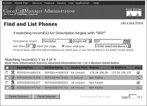
You can also control the number of items that display in list boxes, which directly affects how fast some pages display in CallManager Administration.
Table A-16 provides information about enterprise parameters relating to CallManager Administration (System > Enterprise Parameters).
|
Enterprise Parameter |
Default |
Valid Values |
|---|---|---|
|
Max List Box Items The maximum number of items that display in a list box in the pages in CallManager Administration and BAT (for example, partition, calling search space, and voice mail profile). For any value above the number that is specified in this parameter, only the default (such as None) and the currently selected items appear in the list box, and a lookup (...) button appears to the right of the list box. See Figure A-5 for an example of the lookup button. Click the lookup button to find and choose the desired item. Increasing the value above the default sends more items directly to the browser but results in slower page loads in a large system. Decreasing the value sends fewer items directly to the browser and results in faster page load for a large system. You need to close and reopen the browser for the change to take effect. |
250 |
50 to 9999 items |
|
Max Lookup Items This parameter specifies the maximum number of items that will be sent to the browser when doing a lookup (click the [...] button) for a data entry field (list box). Using a higher value sends more items directly to the lookup browser window (results in slower page load but faster searching). Using a lower value sends fewer items directly to the lookup browser window (results in faster page load but slower search). You need to close and reopen the browser for the change to take effect. |
1000 |
250 to 99999 items |
Figure A-5 shows the Phone Configuration page with a lookup button on the fields Calling Search Space and AAR Calling Search Space.
Figure A-5. Lookup (...) Button in CallManager Administration
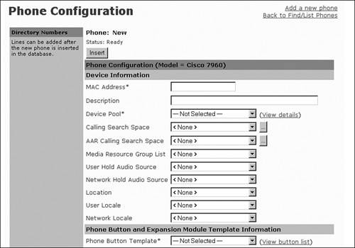
Cisco CallManager Attendant Console (Formerly Cisco WebAttendant)
Note
Cisco CallManager Attendant Console replaces the Cisco WebAttendant application. Attendant Console retains all of the features of Cisco WebAttendant plus introduces many new enhancements. Attendant Console is compatible with CallManager release 3.1(2c) and later. Support for Cisco WebAttendant was removed in CallManager release 3.3.
Cisco CallManager Attendant Console allows one or more live attendants to answer and handle inbound and outbound calls that are not serviced by Direct Inward Dial (DID), Direct Outward Dial (DOD), or automated attendant functions. Attendant Console is a client/server application consisting of Attendant Console, the client application used by the live attendant (receptionist), and Telephony Call Dispatcher (TcdSrv), the server application that extends telephony services to Attendant Console clients and performs the hunt group routing function. Line state server (LSS) monitors line and device status in the cluster and is one of the functions of the Telephony Call Dispatcher.
Attendant Console provides the following features:
- Busy or available indication
- Call status (date, duration, number)
- Drag-and-drop transfer
- Call queuing
- Multiple call distribution algorithms
- Advanced directory search
- Accessibility support for visually impaired users
- Localization to all languages for which CallManager provides user locales
See Appendix B for more information about Cisco CallManager Attendant Console.
Table A-17 provides information about the Attendant Console service parameter that is configurable in the Cisco CallManager service (Service > Service Parameters > select a server > Cisco CallManager).
|
Service Parameter |
Default |
Valid Value |
|---|---|---|
|
Line State Update Enabled Specifies whether the Line State Server can track the active/inactive states of each directory number. Restart the Cisco CallManager service or reregister the directory number for the parameter change to take effect. |
True |
True or False |
Table A-18 provides information about Attendant Console service parameters, which are configurable in the Cisco Telephony Call Dispatcher service (Service > Service Parameters > select a server > Cisco Telephony Call Dispatcher).
|
Service Parameter |
Default |
Valid Value |
|---|---|---|
|
Allow Routing with Unknown Line State Determines whether calls get routed to a line in the hunt group even if the state of the line is unknown. Sometimes line states are not available for some devices; setting this parameter to True allows calls to be routed to devices with unknown line states. Set this parameter to True if you configure hunt groups that contain devices that do not have line states, such as FXO ports connected to analog voice mail ports. |
False |
True or False |
|
Cisco CallManager Line State Port Designates the port number of the TCP/IP port in CallManager that is used by the line state server to register and receive line and device information. |
3223 |
1024 to 65535 Cisco recommends that the default value be used; however, any port can be used as long as it has been properly configured on all clients and servers |
|
Cisco Telephony Call Dispatcher Server Listening Port Specifies the UDP port that Attendant Console clients use to register with the Telephony Call Dispatcher server (TcdSrv) for call control. Keep this parameter set to the default value unless a Cisco support engineer instructs otherwise. |
4321 |
1024 to 65535 |
|
CTI Request Timeout Specifies the time that Attendant Console will wait for the CTIManager to respond to a Redirect request. If a response is not received within the specified time, Attendant Console drops the call. Note
|
15 seconds |
15 to 60 seconds |
|
Directory Sync Period Specifies the interval between synchronization of the Attendant Console server (TcdSrv) UserList with the CallManager DC Directory (any LDAP directory integrated with CallManager; for example, Active Directory). User information such as new users, deleted users, or modified user information does not get synchronized between TcdSrv and CallManager DC Directory until the time specified in this timer has elapsed, which triggers synchronization. A value of 0 disables directory synchronization. |
3 hours |
0 to 720 hours |
|
Keep Original Called Party If Forwarded Determines whether the directory number of the original called party gets reset to the redirected number if the call is forwarded to the pilot point. |
True |
True or False |
|
LSS Access Password Specifies the password that the line state server uses for authentication at registration time. The default is "private". |
private |
Any range of up to 7 alphanumeric characters. Cisco recommends you do not change the default value |
|
LSS Listening Port Designates the UDP port that Attendant Console clients use to register with the Attendant Console server (TcdSrv) for line and device state information. |
3224 |
1024 to 65535 Cisco recommends that the default value be used; however, any port can be used as long as it has been properly configured on all clients |
|
Redirect With Directing Party CSS Specifies whether the redirecting party's (that is, the pilot point) calling search space (CSS) is used when the Attendant Console server (TcdSrv) redirects the call to its agent. |
True |
True or False |
|
Reset Original Called Party on Redirect Determines whether to reset the directory number of the original called party during redirect to the redirected number. The Keep Original Called Party If Forwarded parameter can override the value that is specified in this parameter if the call was forwarded to the pilot point. |
True |
True or False |
Cisco CallManager Serviceability
CallManager Serviceability, a web-based application, provides management and monitoring tools for the CallManager system, including the following:
- Detailed alarm definitions and configuration
- Trace configuration, analysis, and collection
- Control center and service activation, which provides start/stop and activate/deactivate services in the CallManager system
- QRT Viewer, which, if configured, enables you to view log files for IP phone problems reported by IP phone users
- Serviceability Reports Archive, which, if configured, provides auto-generated alert, call activity, and statistics reports
- Component version information (click Help > Component Versions) to see version numbers for the various components in the system on a server-basis
- Access to install the Real-Time Monitoring Tool, which monitors the performance of IP Telephony components in a CallManager cluster
CallManager Serviceability is available from CallManager Administration (Application > Cisco CallManager Serviceability). Chapter 6 provides detailed information about CallManager Serviceability.
Cisco CallManager Trace Collection Tool
The Trace Collection Tool collects traces for a CallManager cluster into a single.zip file. The collection includes all traces for CallManager and logs such as Event Viewer (Application, System, Security), Dr. Watson log, Cisco Update, Prog Logs, RIS DC logs, SQL and IIS logs. You can learn more about the Trace Collection Tool in Chapter 6.
Cisco CallManager User Options Web Page
The Cisco CallManager User Options (CCMUser) web page allows users to program various functions on their IP Phones, such as setting speed dial buttons (if applicable), changing their PIN (for extension mobility), changing their password, configuring IP phone services (if applicable), setting message waiting indicator and call forwarding directives, and more.
Table A-19 describes enterprise parameters (System > Enterprise Parameters) that control which options are provided on the CCMUser web page. Changes to these parameters take effect during the next login to the CCMUser web page. Only those options that are valid for each phone type can be displayed in CCMUser when these parameters are enabled. For example, a phone that does not support speed dial will not display speed dial settings even if the Show Speed Dial Settings parameter is enabled.
|
Enterprise Parameter |
Default |
Valid Values |
|---|---|---|
|
Show Ring Settings Determines whether the option to change the ring settings on a phone appears on the CCMUser web page. |
False |
True or False |
|
Show Call Forwarding Determines whether the option to set call forwarding on a phone appears on the CCMUser web page. |
True |
True or False |
|
Show Speed Dial Settings Determines whether the option to add or update speed dial settings on a phone appears on the CCMUser web page. |
True |
True or False |
|
Show Cisco IP Phone Services Settings Determines whether the option to view and change IP Phone XML services on a phone appears on the CCMUser web page. |
True |
True or False |
|
Show Personal Address Book Settings Determines whether users can view and change Personal Address Book settings on the CCMUser web page. |
True |
True or False |
|
Show Message Waiting Lamp Policy Settings Determines whether the option to view and change the message waiting lamp policy on a phone appears on the CCMUser web page. |
True |
True or False |
|
Show Line Text Label Settings Determines whether the option to configure line text label for a phone appears on the CCMUser web page. If the user's current device has line(s) configured, the user can view and change the line text label for each line on that phone unless the line is the primary line. |
False |
True or False |
|
Show Locale for Phone Settings Determines whether the option to change the locale for this phone appears on the CCMUser web page. |
True |
True or False |
|
Show Locale for Web Pages Settings Determines whether the option to change the locale for web pages appears on the CCMUser web page. If this parameter is enabled, users can view and change the user locale setting for extension mobility and the CCMUser web page. |
True |
True or False |
|
Show Change Password Option Determines whether the option to change the password for a user appears on the CCMUser web page. |
True |
True or False |
|
Show Change PIN Option Determines whether the option to change the PIN for a user appears on the CCMUser web page. |
True |
True or False |
|
Show Download Plugin Option Determines whether the option to download and install plug-ins for a user appears on the CCMUser web page. |
True |
True or False |
|
Show Online Guide Option Determines whether the option to display the online phone guide appears on the CCMUser web page. |
True |
True or False |
|
Enable All User Search Determines whether to allow a search for all users (search with no last name/first name/directory number specified) when searching for users via the Corporate Directory from the phone. This parameter also applies to the directory search in CallManager Administration. |
True |
True or False |
|
User Search Limit Specifies the maximum number of users to be retrieved from a search in the Corporate Directory feature on the phone. This parameter also applies to the directory search in CallManager Administration. Search does not apply when the Enable All User Search enterprise parameter is set to False and no criteria are set for the search. |
64 |
1 to 500 |
The Cisco CallManager User Options web page, available in multiple languages, is password-protected and uses LDAP for password authentication. See Appendix B for more information about the Cisco CallManager User Options web page.
Cisco Conference Connection (CCC) Support
CallManager integrates with Cisco Conference Connection, which is a Meet-Me audio conferencing solution. Conferences are scheduled from an intuitive web-based conference-scheduling interface. Conference participants call in to a central number, enter a meeting identification number (and optionally a password), and are then placed into the conference. At the discretion of the conference organizer, conference participants using Cisco IP Phones 7940, 7941, 7960, 7961, 7970, and 7971 can join meetings at the touch of a button via the Cisco Conference Connection XML service.
Learn more about other conferencing options in Appendix B.
Cisco CTL Client
The CTL Client plug-in retrieves the CTL file from the Cisco TFTP server. It digitally signs the CTL file by using a security token and then updates the file on the Cisco TFTP server.
The Cisco CTL Provider service provides one service parameter relating to CTL configuration (Service > Service Parameters > select a server > Cisco CTL Provider), as described in Table A-20.
|
Service Parameter |
Default |
Valid Values |
|---|---|---|
|
Port Number Specifies the port number to use for opening a Transport Layer Security (TLS) connection between the Certificate Trust List (CTL) clients and the CTL provider. The CTL clients must connect using the port specified in this parameter. |
2444 |
1027 to 32767 |
Cisco Discovery Protocol (CDP) Support
Cisco IP Phones 79xx utilize CDP upon initialization to negotiate with the upstream switch. This also allows the exact physical location of the phones (that is, to which switch port they are connected) to be auto-discovered by device tracking applications such as CiscoWorks and Cisco Emergency Responder. Phones also use CDP to negotiate power requirements with the switch as well as voice VLAN information.
In addition, CallManager and applications that run on Cisco MCS server platforms also use CDP so that CiscoWorks can auto-discover the servers in the network.
Cisco Emergency Responder (CER) Support
Cisco Emergency Responder is an emergency call routing and reporting solution that dynamically addresses the need to identify the location of 911 callers in the North American numbering plan (NANP) in an emergency, with no administration required when phones and/or people move from one location to another. CER tracks the location of IP phones in real time through SNMP and CDP mechanisms.
Appendix B provides additional information on CER.
Cisco IP Manager-Assistant
See the "Manager Assistant Services" section later in this appendix for more information about Cisco IP Manager-Assistant.
Cisco IP Phone 7902, 7905, 7912, Expansion Module 7914, Wireless 7920, Conference Station 7936 and 7935, 7940, 7941, 7960, 7961, 7970, and 7971 Support
CallManager supports many different Cisco IP Phones, as covered in greater detail in Chapter 3, "Station Devices." You can also learn more about Cisco's phone product offerings at the following link or search Cisco.com for "Cisco IP Phones":
http://www.cisco.com/en/US/products/hw/phones/ps379/index.html
Table A-21 describes enterprise parameters (System > Enterprise Parameters) that specify URLs for Cisco IP Phones.
|
Enterprise Parameter |
Default |
Valid Values |
|---|---|---|
|
URL Authentication Specifies the URL that points to a web page that resides in one of the Cisco CallManager Cisco IP Phone (CCMCIP) webs in the cluster. This URL provides an authentication proxy service between Cisco IP Phones 7940, 7941, 7960, 7961, 7970, 7971 and the LDAP directory. This URL gets used to validate requests made directly to the phone. This URL is automatically configured at install time. If the URL is removed, the push capabilities to Cisco IP Phones will be disabled. |
No default value |
Up to 255 characters in the format of a well-formed URL (for example, http://myserver/myscript.asp) Test the URL in a separate browser window to make sure that it is valid |
|
URL Directories Specifies the URL that Cisco IP Phones 7940, 7941, 7960, 7961, 7970, and 7971 use when the directories button is pressed. This URL must return a CiscoIPPhoneMenu object even if no MenuItems are specified in the object. The MenuItems that are specified get appended to the directory list along with the three internal directories on the Cisco IP Phones. You can learn more about the CiscoIPPhoneMenu object in Appendix C, "Protocol Details." |
No default value |
Up to 255 characters in the format of a well-formed URL |
|
URL Idle Specifies the URL that Cisco IP Phones 7940, 7941, 7960, 7961, 7970, and 7971 use to display information on the screen when the phone remains idle for the time that the URL Idle Time parameter specifies. |
No default value |
Up to 255 characters in the format of a well-formed URL |
|
URL Idle Time Specifies the time that Cisco IP Phones 7940, 7941, 7960, 7961, 7970, and 7971 should remain idle before displaying the URL that the URL Idle parameter specifies. If the time is set to zero, the URL that the URL Idle parameter specifies will not display. |
0 seconds (disabled) |
0 to 604800 seconds |
|
URL Information Specifies a URL that points to a page in the Cisco CallManager Cisco IP Phone (CCMCIP) webs and returns the requested help text to the display on Cisco IP Phones 7940, 7941, 7960, 7961, 7970, and 7971. This information displays when a user presses the i or ? button on the phone. |
No default value |
Up to 255 characters in the format of a well-formed URL |
|
URL Messages Specifies a URL that the Cisco IP Phones should load when the messages button is pressed. The URL must return a CiscoIPPhoneMenu object when called. The MenuItems that are returned get appended to the built-in items on Cisco IP Phones 7940, 7941, 7960, 7961, 7970, and 7971. |
No default value |
Up to 255 characters in the format of a well-formed URL |
|
IP Phone Proxy Address Specifies a proxy server name or address and port (for example, proxy.cisco.com:8080). If the proxy server is specified, Cisco IP Phones use it to request all URLs. Leave this setting blank for the phones to attempt to connect directly to all URLs. If a name is used instead of an IP address, configure phones with valid DNS servers to allow name-to-IP resolution. Confirm that the proxy server is listening at the destination that is specified. |
No default value |
Proxy server name or address and port (for example, proxy.cisco.com:8080), up to 255 characters |
|
URL Services Specifies the URL that Cisco IP Phones call when a user presses the services button. The initial request by the phone passes the device name as a parameter. The default page in the Cisco CallManager Cisco IP Phone (CCMCIP) web returns a CiscoIPPhoneMenu object with a list of services that are subscribed to the device. If no subscriptions exist, the return text indicates that no subscriptions exist for the device. |
No default value |
Up to 255 characters in the format of a well-formed URL |
Cisco IP Phone Services
An XML application programming interface (API) works in conjunction with XML-capable Cisco IP Phones to offer custom-configured services. XML primitives include the ability to overwrite softkey set definitions, which allows for remapping of the existing functionality and labels to different keys and adding new keys with associated URLs for application control. A mechanism such as an icon is also provided to indicate to the user that an instant message has been received.
Appendix C provides more information about the XML functionality available in the form of an XML Software Development Kit (SDK).
Cisco IP Software-Based Phone Support (IP SoftPhone and IP Communicator)
CallManager provides support for Cisco IP SoftPhone and Cisco IP Communicator, virtual telephones that run on the user's desktop. Using virtual private networks (VPN), users can use any Internet connection while on the road to handle calls on their extensions as if they were in the office. The software-based IP phones have all of the features of a desktop business telephone, including hold, transfer, mute, Ad Hoc and Meet-Me conferencing, redial, caller ID display, voice mail integration, dial pad by keyboard or onscreen, context-sensitive online help, and more.
Cisco IP SoftPhone Support for Microsoft NetMeeting
Cisco IP SoftPhone can launch the following applications for Microsoft NetMeeting if a collaborative PC is configured:
- Application sharing
- Chat
- File transfer
- Video
- White board
Refer to Microsoft documentation for more information about each of these features.
Cisco Personal Address Book
Cisco Personal Address Book is an IP phone application that lets users store and retrieve their personal address book entries from their IP phone. Personal Address Book consists of two IP phone services to which users can subscribe. The PersonalAddressBook service allows users to search and view their address book entries and dial a corresponding directory number from the Cisco IP Phone. The PersonalFastDials service is similar to a speed dial button on the IP phone. When the user selects the service using the services button, a list of fast dial entries displays in menu format. The user can select a menu item by entering the index number on the IP phone's keypad. The corresponding directory number is then automatically dialed.
The Cisco IP Phone Address Book Synchronizer plug-in (Application > Install Plugins) allows users to synchronize their Microsoft Outlook and Outlook Express address book entries with Cisco Personal Address Book. The Cisco IP Phone Synchronizer performs the synchronization process on the user's desktop.
This feature works with Cisco IP Phones 7905, 7912, 7920, 7940, 7941, 7960, 7961, 7970, and 7971 and requires configuration in CallManager Administration. For users to have access to Personal Address Book, you must first configure the PersonalAddressBook and PersonalFastDials services in CallManager Administration (Feature > Cisco IP Phone Services). To allow users access to the Synchronization utility, you must download the plug-in (Application > Install Plugins) and post it to a location that users are aware of and can access.
Users can subscribe to Cisco Personal Address Book services on the Cisco CallManager User Options web page. They can also synchronize their contact information there, as well as configure their Personal Address Book.
Cisco VG248 48-Port Analog Gateway Support
The Cisco VG248 Analog Phone Gateway, a high-density, 48-port FXS gateway, enables you to integrate analog telephones, modems, and fax machines with the CallManager system. Because it runs SCCP, the connected POTS phones have traditional telephony features associated with them, which are accessible to the user through configurable feature codes. These features include blind transfer, hold/resume, MWI (stutter dial tone), calling line ID, Ad Hoc conferencing, call waiting, and call park. The VG248 represents an alternative to IP phones for simple POTS phone users who also require extended telephony features.
Using version 1.1(1) or later of the VG248 software, you can integrate legacy voice mail and PBX systems with CallManager using Simplified Message Desk Interface (SMDI) and analog FXS connections on the VG248.
CISCO-CCM-MIB Updates
Simple Network Management Protocol (SNMP) Management Information Base (MIB) tables organize and distribute the information gathered from your company site. Additional objects are routinely added to the CISCO-CCM-MIB tables. You can view the MIBs at the following locations:
http://tools.cisco.com/Support/SNMP/do/BrowseMIB.do?local=en&mibName=CISCO-CCM-MIB
http://www.cisco.com/public/sw-center/netmgmt/cmtk/mibs.shtml
ftp://ftp.cisco.com/pub/mibs/v2/CISCO-CCM-MIB.my
You can learn about MIB tools at the following location:
http://tools.cisco.com/ITDIT/MIBS/servlet/index
See the section "Simple Network Management Protocol (SNMP) Support" for additional information.
Click to Dial/Click to Call
CallManager supports click to dial/call in several forms:
- Cisco IP Phones that provide directory access via the directories button offer one-touch dialing from available directories and call initiation from a list of missed, received, and placed calls. The Dial softkey allows users to dial the displayed directory listing or missed/placed/received call just by pressing the softkey. An EditDial softkey allows the user to modify the displayed number before dialing.
- The WebDialer application offers click to dial services. See the "Cisco WebDialer Click-to-Dial Service" section for more information.
- CTI integration via third-party software solutions offers click to dial services. See the "Computer Telephony Integration (CTI) Support" and the "Telephony Application Programming Interface (TAPI) and JTAPI Support" sections for more details.
Cisco WebDialer Click-to-Dial Service
Cisco WebDialer allows Cisco IP Phone users to place calls by clicking a hyperlink in web applications or other desktop applications (for example, click-to-call from within your Microsoft Outlook address book). In CallManager release 3.3(3), WebDialer is downloaded from Cisco.com and installed on your CallManager server. In CallManager release 3.3(4) and later, WebDialer is an integrated service of CallManager that you enable. Integrating with other applications is achieved using the publicly documented API, available at the following link:
http://www.cisco.com/univercd/cc/td/doc/product/voice/c_callmg/3_3/sys_ad/3_3_4/ccmfeat/fswbdlr.htm
The Cisco WebDialer service provides several service parameters relating to WebDialer configuration (Service > Service Parameters > select a server > Cisco WebDialer), as described in Table A-22.
|
Service Parameter |
Default |
Valid Values |
|---|---|---|
|
List of WebDialers Specifies a space-separated list of IP addresses for all WebDialers in the enterprise; for example, one IP address in San Jose, one in Dallas, one in London, and so on. For multiple IP addresses, leave a space between each IP address (for example, 123.45.67.89 123.55.67.90). You need to use this optional parameter only if you are configuring a redirector. Restart the Cisco Tomcat service for the parameter change to take effect. |
No default value |
Up to 1024 characters Entry should contain a valid IP address (for example, 123.45.67.89). Separate IP addresses by space if specifying more than one WebDialer (for example, 123.45.67.89 123.45.67.90) |
|
Primary Cisco CTIManager Specifies the IP address of the primary CTIManager. Restart the Cisco Tomcat service for the parameter change to take effect. |
127.0.0.1 |
Up to 15 digits in the form of an IP address (for example, 123.45.67.89) |
|
Backup Cisco CTIManager Specifies the IP address of the backup CTIManager. Restart the Cisco Tomcat service for the parameter change to take effect. |
No default value |
Up to 15 digits in the form of an IP address (for example, 123.45.67.89) |
|
User Session Expiry Specifies the time after which the user session will expire. A value of 0 indicates that the session will never expire. Restart the Cisco Tomcat service for the parameter change to take effect. |
0 |
0 to 168 hours |
|
Duration of End Call Dialog Specifies the duration for which the End Call dialog displays. The End Call dialog allows users to end the call when they made the call in error. Restart the Cisco Tomcat service for the parameter change to take effect. |
15 seconds |
10 to 60 seconds |
|
Apply Application Dial Rules on Dial Specifies whether application dial rules must be applied when the user presses the Dial button. WebDialer applies dial rules before displaying the Make Call screen. Setting this parameter to True causes WebDialer to apply the dial rules again when the user clicks the Dial button in the Make Call screen. |
True |
True or False |
Learn more about WebDialer in Appendix B.
Client Matter Codes
Client matter codes (CMC) facilitate call accounting and billing for billable clients. The client matter codes feature forces the user to enter a code to identify calls that relate to a specific client.
To use the CMC feature, you enable CMC through route patterns, and then configure CMC (Feature > Client Matter Code). When a user dials a number that is routed through a CMC-enabled route pattern, a tone prompts the user to enter the client matter code. When the user enters a valid CMC, the call is routed to the dialed number. The CMC used on the call writes to the CDR so you can collect the information via the CDR Analysis and Reporting (CAR) tool or a third-party CDR application. If the user enters an invalid code, the call is not routed and the user hears reorder tone.
CMC can be used alone or in conjunction with forced authorization codes. See the "Forced Authorization Codes" section for more information.
Codec Support (Audio and Video)
CallManager supports numerous audio and video codec formats and is capable of selecting which codec should be used, on a call-by-call basis, through the use of regions and through the knowledge of what each device's codec capabilities are. See the "Automatic Bandwidth Selection" section for more information.
Tables A-23 and A-24 correlate CallManager releases to the supported codecs. However, in many cases, even though CallManager supports a particular codec, the endpoint device (phone, video terminal, transcoder, conference bridge, application, and so on) might not support it. For this reason, the codec that is chosen for a given call is a combination of the following:
- Which codecs each device participating in the call supports
- Which codecs CallManager supports
- What the region configuration dictates should be used
|
CallManager Release |
G.711 A-law/G.711 m-law |
G.722 |
G.722.1 |
G.728 |
G.729a/G.729b/G.729ab |
Cisco Wideband Audio (16-Bit/16 kHz) |
|---|---|---|---|---|---|---|
|
3.0(x) |
Yes |
No |
No |
No |
Yes |
No |
|
3.1(x) |
Yes |
No |
No |
No |
Yes |
Yes |
|
3.2(x) |
Yes |
No |
No |
No |
Yes |
Yes |
|
3.3(x) |
Yes |
No |
No |
No |
Yes |
Yes |
|
4.0(x) |
Yes |
Yes |
No |
Yes |
Yes |
Yes |
|
4.1(x) |
Yes |
Yes |
No |
Yes |
Yes |
Yes |
|
CallManager Release |
H.261 |
H.263 |
H.264 |
Cisco Wideband Video |
|---|---|---|---|---|
|
3.0(x) |
No |
No |
No |
No |
|
3.1(x) |
No |
No |
No |
No |
|
3.2(x) |
No |
No |
No |
No |
|
3.3(x) |
No |
No |
No |
No |
|
4.0(x) |
Yes |
Yes |
No |
Yes |
|
4.1(x) |
Yes |
Yes |
Yes[*] |
Yes |
[*] H.264 is supported only on SCCP endpoint devices in CallManager release 4.1(2)
Table A-25 describes service parameters (Service > Service Parameters > select a server > Cisco CallManager) that control media-related details.
|
Service Parameter |
Default |
Valid Values |
|---|---|---|
|
Media Exchange Interface Capability Timer Specifies the maximum amount of time that CallManager will wait for media connection to be set up between two parties. This timer pertains to media connection that occurs at the device interface level. |
8 seconds |
0 to 300 seconds |
|
Media Exchange Timer Specifies the maximum amount of time that CallManager will wait for a media connection to be established. If the media connection is not established within the specified time, the user will hear reorder tone. The default value normally provides sufficient leeway; however, for a heavily congested network, you can use a larger value. |
12 seconds |
0 to 300 seconds |
|
Media Exchange Stop Streaming Timer Specifies the maximum amount of time that CallManager will wait to receive a response to a StopStreaming request. If the response is not received within the specified time, CallManager terminates the call. |
8 seconds |
3 to 300 seconds |
|
Media Resource Allocation Timer Specifies the maximum amount of time that CallManager will wait for a media resource to be allocated. If a media resource is not allocated within the specified time, CallManager rejects the media resource allocation request. The default value normally provides sufficient leeway; however, for a heavily congested network, you can use a larger value. |
12 seconds |
0 to 60 seconds |
|
[*] Strip G.729 Annex B (Silence Suppression) from Capabilities Determines whether the system will advertise or negotiate Annex B for G.729 codecs. True means that the system will not advertise or negotiate Annex B for G.729 codecs, unless that is the only matching codec (G.729b or G.729ab). Annex B provides silence suppression. If you are using a device that only advertises G.729b and/or G.729ab, the potential exists for the call to fail due to a capabilities mismatch. If the system can detect the mismatch, it will try to connect the call with Annex B anyway; however, if the call involves an intercluster trunk, this may not be possible and a transcoder may be allocated or the call may fail. As the solution, reconfigure the device to support other capabilities (such as G.729 or G.729a) if possible. Also, remember that this service parameter works independently from the other systemwide parameters Silence Suppression and Silence Suppression for Gateways. Those parameters only determine whether silence suppression is enabled in SCCP and MGCP, but this setting does not affect the capabilities negotiation. Some devices will override the value of this parameter on the basis of the negotiated capability. |
False |
True or False |
|
Enforce Millisecond Packet Size Determines whether an audio channel is allowed if it does not comply with the advertised millisecond packet size. True means that an audio channel is only allowed when its millisecond packet size is within the setting specified in the "Preferred G.7xx Millisecond Packet Size" parameters; False means that an audio channel is always allowed because its millisecond packet size is not being checked or enforced. |
True |
True or False |
|
Preferred G711 Millisecond Packet Size Specifies the preferred size for delivering G.711 packets. To avoid adding latency, the valid values specify 10, 20, or 30 milliseconds. |
20 milliseconds |
10, 20, or 30 milliseconds |
|
Preferred G723 Millisecond Packet Size Specifies the preferred size for delivering G.723 packets. To avoid adding latency, the valid values specify 30 or 60 milliseconds. |
30 milliseconds |
30 or 60 milliseconds |
|
Preferred G729 Millisecond Packet Size Specifies the preferred size for delivering G.729 packets. To avoid adding latency, the valid values specify 10, 20, 30, 40, 50, or 60 milliseconds. |
20 milliseconds |
10, 20, 30, 40, 50, or 60 milliseconds |
|
Preferred GSM EFR Bytes Packet Size Specifies the preferred number of bytes per 20-ms sample for the GSM EFR codec. Regardless of the total sample size, this parameter specifies whether each 20-ms sample will contain 31 bytes or 32 bytes. |
31 bytes |
31 or 32 bytes per 20-ms sample size |
[*] The Strip G.729 Annex B (Silence Suppression) from Capabilities parameter must be set to the same value on every node in the cluster
Cisco Wideband Audio Codec Support
Cisco wideband audio codec is a Cisco-proprietary encoding method that provides 16-bit/16-kHz sampling. It is supported only on the following devices:
- Cisco IP Phone 7910, 7940, 7941, 7960, 7961, 7970, and 7971
- Cisco IP Voice Media Streaming App service (for Music on Hold)
Cisco Wideband Video Codec Support
Cisco wideband video codec is a Cisco-proprietary encoding method that provides 30 frames per second 320 x 240 resolution video at 7 Mbps. It is supported only on Cisco VT Advantage. See the "Video Telephony Support" section for more details.
GSM-EFR/FR Support Through Use of Hardware Transcoder
CallManager supports Groupe Speciale Mobile-Enhanced Full Rate/Full Rate (GSM-EFR/FR). Cisco IP Phones do not natively support the GSM-EFR/FR codecs so a hardware transcoder must be used. This feature also allows calls from a GSM phone (in conjunction with a third-party service provider) to a G.729 or G.711 endpoint.
H.261 and H.263 Video Codec Support
CallManager supports H.261 and H.263 codecs (for SCCP and H.323 devices only). See the "Video Telephony Support" section for more details.
H.264 Video Codec Support
Note
This feature was introduced in CallManager 4.1(2).
This release adds support for H.264 codec (for SCCP devices only). See the "Video Telephony Support" section for more details.
G.728 and G.722 Audio Codec Support
CallManager supports G.728 and G.722 audio codecs typically used by H.323 videoconferencing devices. See the "Video Telephony Support" section for more details.
Closest Match Routing
The closest match routing process routes a call using the route pattern that most closely matches the dialed number. When CallManager encounters a dialed number that matches multiple route patterns, it uses closest match routing to determine which route pattern most closely matches the number and directs the call using that route pattern.
You can learn more about closest match routing in Chapter 2, "Call Routing."
Clustering
A cluster consists of a set of CallManager nodes that share the same database and resources. This allows the load of processing calls and other functions to be distributed across multiple servers to achieve scalability. Each server in the cluster can be configured to perform one or more of the following functions:
- Publisher server
- TFTP server
- Application software server
- Primary call processing node
- Backup call processing node
- Music on Hold server
- Software conferencing server (for Ad Hoc conferences or Meet-Me conferences)
Chapter 1, "Cisco CallManager Architecture," provides more information about clustering, including the maximum number of IP phones per cluster and redundancy schemes.
Computer Telephony Integration (CTI) Support
CallManager provides CTI support through TAPI/JTAPI interfaces. Scalability and redundancy for CTI applications is provided by the CTIManager service, which runs on one or more CallManager nodes in a cluster.
Software Developer Kits (SDK) are provided for application programmers who want to integrate CTI applications into CallManager. See the "Telephony Application Programming Interface (TAPI) and JTAPI Support" section for more information.
Conference/Confrn
Note
CallManager provides two types of conferences: Ad Hoc and Meet-Me. Ad Hoc conferences require the conference controller to include attendees to the conference by calling them individually. Meet-Me conferences allow attendees to dial in to the conference after the conference controller has established the conference. Ad Hoc conferences are identified simply by the term conference, while Meet-Me conferences are identified by the term Meet-Me. This section describes the Conference feature. Meet-Me is covered in this appendix in the section "Meet-Me Conference/MeetMe."
Conference allows a user to establish a conference, call individual attendees, and connect them to that conference. Conference is available for all Cisco IP Phones. On Cisco IP Phones that use buttons rather than softkeys, such as 12SP+, 30VIP, and 7910, the button is called Conference and must be configured on the button template. On Cisco IP Phones that have softkeys, such as 7971 and 7961, the softkey is called Confrn and is automatically available during an active call. The Conference button/Confrn softkey is not used to participate in a conference call, only to initiate one.
To establish a conference, the user, known as a conference controller, calls the first conference attendee. When connected to that party, the conference controller presses the Conference button or Confrn softkey. The called party is placed on hold, and the conference controller hears a dial tone. At the dial tone, the conference controller dials the next conference participant and, after connecting to that party, presses the Conference/Confrn button again to connect all three parties and establish the conference. The conference controller can continue to add attendees in this fashion until the maximum number of allowed participants is reached or until there are no more bridge ports available. Conference attendees and the conference controller can depart the conference at any time. As long as there are two conference attendees, the conference will remain in effect, but without the conference controller, no additional attendees can be added. Figure A-6 illustrates the conference operation.
Figure A-6. Conference Operation (Ad Hoc)
Table A-26 provides information about Ad Hoc conference service parameters (Service > Service Parameters > select a server > Cisco CallManager).
|
Service Parameter |
Default |
Valid Values |
|---|---|---|
|
Suppress MOH to Conference Bridge Determines whether music on hold (MOH) plays to a conference when a conference participant places the conference on hold. |
True |
True or False |
|
Drop Ad Hoc Conference Note This service parameter was introduced in CallManager release 3.3(4) and enhanced in release 4.1(2). Determines how an Ad Hoc conference terminates. |
Never |
NeverThe conference remains active a) after the conference controller hangs, and b) after all OnNet parties hang up. Be aware that choosing this option means that if OnNet parties conference in OffNet parties and then disconnect, the conference stays active between the OffNet parties, which could result in potential toll fraud When Conference Controller LeavesTerminate the conference when the conference controller hangs up or when the conference controller transfers, redirects, or parks the conference call and the retrieving party hangs up When No OnNet Parties Remain in ConferenceTerminate the conference when there are no OnNet parties remaining in the conference |
|
Maximum Ad Hoc Conference Specifies the maximum number of participants that are allowed in a single Ad Hoc conference. The value you specify in this field depends on the capabilities of the software/hardware conference bridge. The maximum number of conference bridge participants for typical conference bridges follow: Software Conference 64; Cisco Catalyst WS-X6608: 16; Cisco Catalyst 4000: 16; PVDM2-based IOS gateways: 8; and NM-HDV: 6. Setting this value above the maximum capacity of the conference will result in failed entrance to a conference bridge if you try to add more ports than the specific conference bridge configuration allows. Caution: CTI applications and the Drop Any Party feature (accessed via the ConfList softkey) do not support more than 16 participants. Although an Ad Hoc conference can support more than 16 participants, the participant list used by CTI applications and the Drop Any Party feature will display only the 16 most recent conference participants. |
4 |
3 to 64 |
|
Maximum MeetMe Conference Unicast Specifies the maximum number of participants that are allowed in a single Unicast Meet-Me conference. The value you specify in this field depends on the capabilities of the software/hardware conference bridge; for example, a software conference bridge conferences up to 128 participants. When a conference is created, the system automatically reserves a minimum of 3 streams, so specifying a value less than 3 allows a maximum of 3 participants. |
4 |
1 to 128 |
You can learn more about the Ad Hoc conference feature in Chapter 5.
Drop Last Conference Party
The conference controller can remove the last party added to any Ad Hoc conference by pressing the RmLstC softkey.
List Conference Participants
Conference participants can view the list of conference participants by pressing the ConfList softkey. The conference controller can remove participants from the conference by scrolling to the participant's name and pressing the Remove softkey.
Drop Conference When Initiator Leaves
You can configure Ad Hoc conferences to terminate when the conference controller departs the conference by choosing the When Conference Controller Leaves value of the Drop Ad Hoc Conference service parameter described in Table A-26. The conference will also terminate when the controller transfers, redirects, or parks the conference call and the retrieving party hangs up.
Drop Conference When No OnNet Parties Remain
Note
This feature was introduced in CallManager release 4.1(2).
You can configure Ad Hoc conferences to terminate when only OffNet parties remain in the conference by using the When No OnNet Parties Remain in the Conference value of the Drop Ad Hoc Conference service parameter described in Table A-26. Choosing this value protects against the potential toll fraud case of OnNet parties conferencing in OffNet parties and then disconnecting, allowing the OffNet parties to continue the conversation at the enterprise's expense.
Release Conference Bridge When Only Two Parties Remain
CallManager terminates Ad Hoc conferences when only two conference participants remain in the conference. The call dynamically returns to being a point-to-point call, releasing the conference bridge resource.
Context-Sensitive Help
CallManager Administration provides context-sensitive help on all web pages.
Cisco IP Phones that have an i or ? button provide help for phone features. Help displays on the screen. You can use the i or ? button in three ways:
- Press the i or ? button and then any other key about which you would like information.
- With a feature selected, press the i or ? button twice in quick succession to display help for that feature. For example, press the settings button. A menu displays several options. If you press the i or ? button twice quickly, the help for the selected option displays.
- Press the i or ? button twice in quick succession during an active call to view network statistics about the call.
Contrast/LCD Contrast
The contrast feature in the settings menu on Cisco IP Phones allows the user to adjust the contrast of the display panel on the phone.
CTI Redundancy with CTIManager
The CTI API supports redundancy.
Because CTIManager is a separate service from CallManager, applications can connect to a single CTI to obtain access to resources and functionality of all CallManager nodes in the cluster. CTI provides recovery of failure conditions resulting from a failed CallManager node within a cluster that includes CallManager and the CTIManager service. Recovery and survivability are available for the following:
- CTI port/route point
- Cisco IP Phones
- CTIManager
- Applications
Date/Time Zone Display Format Configurable per Phone
Devices belong to a device pool that designates the appropriate date format and time zone. All Cisco IP Phones display the date and time according to their designated device pool.
Dependency Records
Dependency records show you which records in the CallManager database are dependent on other records in the database. For example, you can determine which devices (such as CTI route points or phones) use a particular calling search space or which device belongs to a specific device pool.
If you need to delete a device pool from CallManager, you can use dependency records to show which devices use that device pool and then reassign the affected devices to a new device pool. You must remove all dependent devices before deleting the device pool.
The capability to generate and display dependency records is controlled by an enterprise parameter, Enable Dependency Records (System > Enterprise Parameters). Close and reopen the web browser for the parameter change to take effect.
Note
Displaying dependency records leads to high CPU usage and takes some time because it executes in a low-priority thread. If you monitor CPU usage, you might see high CPU usage alarms. To avoid possible performance issues, display dependency records only during off-peak hours or during the next maintenance window.
Device Type-Based Information and Resets
You can view and update load information, device pool, and phone template information for all devices in the system, grouped by device type. You can also reset all devices of the same type in the Device Defaults Configuration page in CallManager Administration (System > Device Defaults).
Device Downloadable Feature Upgrade
You can upgrade firmware by downloading a new version on device initialization. You can download upgrades for the following devices:
- Cisco IP Phones and IP conference phones
- Transcoder resources
- Conference bridge resources
- Cisco Catalyst 6000, Cisco Analog Access, and Cisco Digital Access gateways
Device Pool
Device pools (System > Device Pool) reduce administration time for a large system by allowing you to specify criteria that are common among many devices. The following criteria are specified in a device pool:
- Cisco CallManager group
- Date/time group
- Region
- Softkey template
- SRST reference
- Calling search space for auto-registration (optional)
- Media resource group list (optional)
- Network hold music on hold audio source (optional)
- User hold music on hold audio source (optional)
- Network locale (optional)
- User locale (optional)
- Connection monitor duration (optional)
- MLPP indication
- MLPP preemption
- MLPP domain (optional)
Device Search in CallManager Administration
CallManager Administration provides a device search by name, description, calling search space, device type, and more to make locating a specific device in a large system simpler. A complete list of all devices is also available by clicking the Find button without specifying any search criteria. See Figure A-4 for an example of a device search.
Device Wizard
CallManager Administration provides a Device Wizard (Device > Add a New Device) that makes adding individual new devices to CallManager a simple process. You can add single instances of devices such as the following using the Device Wizard:
- CTI route point
- Gatekeeper
- Gateway
- Phone
- Cisco voice mail port
- Trunk
Use BAT to add multiple devices at one time. See the section "Bulk Administration Tool (BAT)" for more information.
DHCP IP Assignment for Phones and Gateways
Cisco IP Phones, gateways, and media resources support the use of Dynamic Host Configuration Protocol (DHCP) for IP address assignment. In addition, the use of the Site Specific Option 150 allows the DHCP server to inform these devices of the address of the TFTP server they should use to retrieve their configuration file(s). See the "Trivial File Transfer Protocol (TFTP) Support" section for more information.
Dial Plan Partitions and Calling Search Spaces
Partitions and calling search spaces are an extremely powerful but complex pair of mechanisms by which you can customize dialing restrictions for individual users. Partitions and calling search spaces allow you to administer such policies as routing by geographic location, routing for multiple tenants, and routing by security level of the calling user. You can learn more about partitions and calling search spaces in Chapter 2.
Dialed Number Analyzer (DNA)
The Dialed Number Analyzer tool (DNA), an installable plug-in for CallManager, runs as a service on the server and it allows you to test a CallManager dial plan configuration prior to deploying it or to analyze dial plans after the dial plan is deployed. You can use the results to diagnose a dial plan, to identify potential problems, and to tune a dial plan.
Dialed Number Translation Table (Inbound and Outbound Translation)
CallManager can translate dialed or received digits.
Dialed Number Identification Service (DNIS) and RDNIS
CallManager supports receiving and passing the called party number/dialed number.
Redirected Number Identification Service (RDNIS)
Collectively, RDNIS support displays the last redirected number as well as the originally dialed number to and from configured devices and applications.
Outbound RDNIS to H.323 Gateways
CallManager supports passing the redirected number (RDNIS) to Cisco IOS H.323 gateways.
Digit Analysis (Calling Party Number and Called Party Number)
CallManager can analyze and process dialed or received digits for any callboth external or internal, inbound or outboundon any route pattern, route group, gateway trunk, or translation pattern.
Digital Signal Processor (DSP) Resource Management
CallManager provides support for DSP devices. When a resource allocation for a device is required (that is, if a call needs a transcoder or initiates or joins a conference), CallManager checks to see whether the number of parties has exceeded the allowed limit. If not, CallManager allows the new party to join the conference if the DSP still has streaming capability. An error message is returned if the DSP is out of streams.
Direct Inward Dial
Direct Inward Dial (DID/DDI) allows a caller outside a company to call an internal extension directly, without the assistance of an operator or attendant.
Direct Outward Dial
Direct Outward Dial (DOD) allows a user to call an external phone number directly, without the assistance of an operator or attendant. Usually an access digit, such as 9, is dialed first to indicate an external call, followed by the external phone number. DOD is supported on all gateway trunk types.
Direct Transfer (DirTrfr)
The direct call transfer feature (DirTrfr softkey) directly transfers two parties on a user's line to each other without including the user. Prior to CallManager release 4.0(1), a user had to use either consultative transfer or blind transfer. Direct transfer works in conjunction with the multiple calls per line feature in which a user can make and/or receive multiple calls on a single line, and then directly transfer them together via the DirTrfr softkey. This action connects the two parties together while simultaneously dropping the party who performed the transfer.
The Block OffNet to OffNet Transfer service parameter discussed in Table A-48 applies to the direct transfer feature.
Directories Button on Cisco IP Phones
The directories button on Cisco IP Phones provides access to the following features as well as other administrator-configured directories:
- Missed Calls
- Received Calls
- Placed Calls
- Corporate Directory
The Corporate (Global) Directory is integrated with CallManager through CallManager Administration (User > Global Directory).
Missed Calls
Missed Calls displays a list of calls that have been received by the phone but not answered. Selecting a call from the list and pressing the Dial softkey automatically speed dials the telephone number of the missed call.
Received Calls
Received Calls displays a list of calls that have been answered by the phone. Selecting a call from the list and pressing the Dial softkey automatically speed dials the telephone number of the received call.
Placed Calls
Placed Calls displays a list of calls that have been made from the phone. Selecting a call from the list and pressing the Dial softkey automatically speed dials the telephone number of the previously placed call.
Corporate Directory
Corporate Directory provides a search feature for users based on first name, last name, or number. You can enter letters or numbers using the dial pad, and then press the Search softkey to return a list of users most closely matching the criteria you entered. You can then select a user in the list and press the Dial softkey to call that person. User information is pulled from your currently configured Lightweight Directory Access Protocol (LDAP) directory.
Directory Dial from Cisco IP Phones
Using the directories button, users can speed dial the number of a missed, placed, or received call on a Cisco IP Phone. See the section "Directories Button on Cisco IP Phones" for more information.
Distinctive Ring: Internal Versus External
All Cisco IP Phones provide a distinction in the ringer behavior for internal and external calls. Internal calls generate one ring, while external calls generate two rings with a very short pause between the rings. You can enable/disable this feature on a per-device basis via the Call Classification field on the Gateway Configuration page in CallManager Administration or systemwide via the Call Classification service parameter (Service > Service Parameters > select a server > Cisco CallManager).
Distinctive Ring Selection
Cisco IP Phone 79xx models provide multiple different ringer sounds, allowing the user to choose a preferred ring or to differentiate the phone from a neighboring user's ringer sound. Distinctive rings can be configured on a per-line basis for those phone models that support multiple line appearances. You can modify or limit the number of the available rings via the ringlist.xml file that is retrieved by the phone via TFTP during boot up. Users can choose their ringer sound by pressing settings > Ring Type on the phone.
Distributed CallManager Server Architecture
Multiple redundant CallManager servers can exist across one or more locations to create a distributed environment. You can learn more about this feature in Chapter 1.
Distributed and Topologically Aware Resource Sharing
CallManager provides a Media Resource Manager (MRM) that is responsible for maintaining a list of available and in-use resources. When a resource (for example, for a conference bridge, transcoder, MOH source) is required for a call, the MRM can allocate resources across the cluster as needed to complete various feature requests. These resources can be pooled using media resource groups (MRG) and media resource group lists (MRGL). You can then dictate which
MRGL a phone, gateway, or CTI device uses by defining the MRGL in the device pool or at the individual device level. Chapter 5 provides complete information about resource management.
Dual-Tone Multi-Frequency (DTMF) Support
Note
SIP inband support was introduced in CallManager release 4.1(2).
All DTMF signals are treated as out of band, and digits can be passed in either direction to/from any device type. The following list shows the DTMF support for each device type:
- SCCPOut of band
- MGCP 0.1Out of band
- TAPI/JTAPIOut of band
- H.323H.245 alphanumeric out of band
- SIPRFC 2833 inband
To interwork between SIP and the other protocols, CallManager inserts a media termination point (MTP) for all SIP calls. The MTP interprets the inband RFC2833 DTMF payloads used by the SIP endpoint and converts them to SCCP out-of-band messages to CallManager. CallManager then converts them to whatever protocol is used by the other endpoint (SCCP, MGCP, or TAPI/JTAPI). Conversely, CallManager interprets the out-of-band DTMF messages sent by SCCP, MGCP, and TAPI/JTAPI endpoints and sends them to the MTP via SCCP. The MTP then converts them to RFC 2833 inband payloads to the SIP endpoint.
Embedded Directory for User Data
CallManager servers provide an LDAP directory for user information.
Emergency 911 Service (E911) Support
CallManager and supporting components provide a complete E911 solution. CallManager provides a sophisticated and flexible solution for E911 call routing and reporting. Its partitioned dial plan allows multiple distributed sites to share a common dial pattern for emergency services (such as 911 in the United States) while allowing the calls to that pattern to be routed out through local site gateways. Call back information and information required by local E911 agents to resolve phone location in the event of an emergency services call is delivered through PRI ISDN trunks or Centralized Automatic Message Accounting (CAMA) trunks. The CAMA solution is achieved through a Cisco IOS-based FXS gateway and a third-party product that translates calling line ID information on the FXS ports to CAMA signaling. You can learn more about routing emergency numbers in Chapter 2.
EndCall
The EndCall softkey on Cisco IP Phones allows the user to disconnect a call with the touch of a softkey, which proves particularly useful when using a headset. The softkey is automatically available, and there are no configuration requirements.
Extension Mobility
Extension mobility allows a user to log in to any IP phone causing it to appear as that user's phone temporarily. By logging in to an IP phone, the user can temporarily convert the phone to adopt his or her line numbers, speed dials, services, and other user-specific properties of an IP phone. This feature is particularly useful in situations where users are not permanently assigned physical phones.
In the past, only system administrators could change phone settings using CallManager Administration. With extension mobility, users can achieve the same effect by way of a user login service on the phone. This service provides an interface by which applications can log users in and out. The login service enforces a variety of policies, including duration limits on phone configuration and authorization to log in to a particular phone. The login service is programmable so that system administrators or third parties can replace some of its components. For example, capabilities such as authenticating by smart card readers or automating the login process according to a desk-sharing web application could be added to the standard login service provided in CallManager. The Cisco Extension Mobility service is installed separately from CallManager, and can be co-resident (on the same server) with CallManager or on a standalone server for additional scalability in large clusters.
Note
Phones that have a specific owner identified in the Owner User ID field on the Phone Configuration page in CallManager Administration cannot be used in conjunction with extension mobility. You need to remove the owner user ID before you configure the phone for extension mobility.
The Cisco Extension Mobility service provides several service parameters relating to extension mobility configuration (Service > Service Parameters > select a server > Cisco Extension Mobility), as described in Table A-27.
|
Service Parameter |
Default |
Valid Values |
|---|---|---|
|
Enforce Maximum Login Time Determines whether the value specified in the Maximum Login Time parameter is enforced. |
False |
True or False |
|
Maximum Login Time Specifies the maximum time that a user is allowed to be logged in to a device, such as 8 hours (in the format 8:00) or 30 minutes (n the format: 30). CallManager ignores this parameter if the Enforce Maximum Login Time parameter is set to False. |
8 hours (8:00) |
Up to 7 digits in the form hours:minutes |
|
Maximum Concurrent Requests Specifies the maximum number of login or logout operations which can occur simultaneously. This maximum prevents the Extension Mobility service from consuming excessive system resources. |
3 |
1 to 100 |
|
Multiple Login Behavior Specifies the behavior for multiple attempted logins by the same user on different devices. |
Multiple Logins Not Allowed |
Multiple Logins AllowedThe same user ID can be logged in to extension mobility on more than one device Multiple Logins Not AllowedA user ID can only be logged into one device Auto LogoutIf a user ID is logged into extension mobility on one device, and the same user ID attempts to login to extension mobility on a different device, the first device automatically logs out |
|
Alphanumeric User ID Specifies whether the user ID to be used is alphanumeric or numeric. Restart the Cisco Tomcat service for the parameter change to take effect. |
True |
TrueUser ID is alphanumeric FalseUser ID is numeric |
|
Remember the Last User Logged In Specifies whether the user ID of the last user logged in on a phone is remembered by the extension mobility application. The default value, False, provides greater security. Restart the Cisco Tomcat Service for the parameter change to take effect. |
False |
True or False |
External Route Plan Wizard
CallManager Administration provides an External Route Plan Wizard that you can use to create a basic route plan for geographically dispersed locations. The wizard uses gateway device settings in CallManager Administration and information you provide, making adding route plans to CallManager a simpler process. You can learn more about this feature in Chapter 2.
External/Internal Trunk Designation
Note
This feature was introduced in CallManager release 4.1(2).
The Call Classification field on the Gateway Configuration page for all gateway trunks enables you to designate whether the trunk should be treated as an internal connection (for example, a trunk to another internal PBX) or as an external connection (for example, a trunk to a central office switch). This designation then affects several aspects of calls to/from the trunk, such as distinctive ring tones, call detail records, and call transfer restrictions.
Failover
See the section "Redundancy/Failover" later in this appendix for information about failover.
FAX/Modem over IP Support
CallManager supports three methods to transmit fax traffic across the IP network and two methods to transmit modem traffic:
- Cisco Fax Relay
- Fax Pass-Through
- T.38 Fax-Relay
- Modem Pass-Through
- Cisco Modem-Relay
Cisco Fax Relay mode is the preferred method to transmit fax traffic. However, if a specific gateway does not support Cisco Fax Relay, the gateway supports Fax Pass-Through.
Cisco Fax Relay
Cisco Fax Relay does not involve CallManager; it is a gateway-controlled fax mode. In fact, most of the fax processing occurs in the digital signal processors (DSP), requiring only packet switching from the main processor (CPU) and some limited signaling to switch to fax mode. Therefore, the CPU overhead is very similar to a normal voice call.
Initially, a voice call is established. When the V.21 preamble is detected at the terminating gateway, the originating and the terminating gateway negotiate the codec type. If the two sides cannot negotiate on a common codec and speed, the fax fails. If negotiation succeeds, the fax transmission begins.
Cisco Fax Relay is supported using MGCP, H.323, or SCCP depending on the specific gateway type. The Cisco voice gateways support as many concurrent fax calls as G.711 voice calls.
The voice gateway demodulates the fax data before crossing the IP network. The voice gateway at the other end of the IP network demodulates it again for transmission to the receiving fax machine.
Fax Pass-Through
In Fax Pass-Through mode, some call modifications occur. Namely, voice activity detection (VAD) is automatically disabled, the echo canceller might be disabled in some cases, the call may "upspeed" to G.711 if a lower bandwidth codec is in use, and the jitter buffers are increased.
T.38 Support
Note
This feature was introduced in CallManager release 4.1(2).
In addition to Cisco Fax Relay and Fax Pass-Through, some of the Cisco voice gateway platforms also support T.38 fax relay. The T.38 fax relay is a standards-based protocol supported on H.323 gateways. Because the T.38 fax relay protocol is standards-based, these gateways can interoperate with third-party T.38-enabled gateways and gatekeepers in a mixed-vendor network.
Forced Authorization Codes
The forced authorization codes feature regulates the types of calls that certain users can place by requiring users to enter a valid authorization code prior to extending calls that are routed through FAC-enabled route patterns. You can enable or disable FAC through route patterns. When a user dials a number that is routed through a FAC-enabled route pattern, a tone plays, prompting the user to enter the authorization code.
You can configure multiple levels of authorization. If the user's authorization code does not meet or exceed the level of authorization required to route the dialed number, the user hears reorder. If the authorization is accepted, CallManager extends the call. The authorization code name is written to the CDR so the information can be collected in the CDR Analysis and Reporting (CAR) tool, which allows you to generate reports for accounting and billing.
This feature can be used for colleges, universities, or any business or organization for whom limiting access to specific classes of calls would be beneficial. Also, by assigning unique authorization codes, you can determine which users placed calls.
For each user, you specify an authorization code and then enable FAC on the relevant route patterns (Route Plan > Route Pattern) by selecting the Require Forced Authorization Code check box and specifying the minimum authorization level for calls through that route pattern. Any user who attempts to dial a number that is routed through that route pattern must have at least the authorization level specified or higher. To implement FAC, you need to devise a list of arbitrary authorization levels and their meanings.
FAC can be used alone or in conjunction with client matter codes. See the "Client Matter Codes" section for more information.
FXO and FXS Support
CallManager supports Foreign eXchange Office (FXO)/Foreign eXchange Station (FXS) ports on essentially any H.323, MGCP, or SIP Cisco voice gateway that offers that type of physical interface.
Group Call Pickup/GPickUp
Group call pickup allows users who belong to one call pickup group to answer incoming calls in other groups. See the section "Call Pickup/Group Call Pickup (PickUp/GPickUp)" for more information.
H.323 Client, Gateway, and Gatekeeper Support
CallManager provides an H.323v2-compliant interface to H.323 clients, gateways, multipoint conference units (MCU), and gatekeepers. As of release 4.1(2), CallManager does not support the T.120 protocol.
H.323v2 Gatekeeper Support
Support is provided for registering multiple CallManager servers in a cluster with a gatekeeper. This provides a scalable way of configuring intersite trunks, and is also used for call admission control. See the "Call Admission Control (CAC)" section for more details.
Multiple Gatekeepers per Cluster
CallManager supports the definition of multiple gatekeepers. This provides the flexibility to configure routes to different gatekeepers for different purposes, such as an internal gatekeeper within the enterprise and another to connect to a service provider's network.
H.323 Call Scalability Improvements
Each CallManager server can handle 1,000 H.323 calls, which means that a cluster with 4 active CallManager servers can support 4000 simultaneous H.323 calls.
H.323 Trunks and Scalability Improvements
CallManager provides H.323 interface support and added enhancements to support administrative scalability, dial plan management, and solution redundancy. Enhancements include the following features:
- Alternate gatekeeper
- Alternate endpoints
- Multiple gatekeepers per clusters
- Simple Bandwidth Resolution Query (BRQ) support
- Adherence to H.323v2 specification of Registration, Admission, and Status (RAS) retries and timers
- Call-by-call automated selection of intercluster trunk (ICT) signaling protocols
- CanMapAlias support (for called party number only)
- Gatekeeper serviceability enhancements (new performance monitor counters and the option of taking a gatekeeper offline for maintenance).
Microsoft NetMeeting Support
All Cisco IP Phones can call Microsoft NetMeeting devices that have been configured in CallManager Administration as an H.323 client, or are reachable through an H.323 gatekeeper.
Videoconferencing Support
CallManager supports H.261 and H.263 video codecs and other necessary mechanisms to fully support H.323 videoconferencing clients. See the "Codec Support (Audio and Video)" section for more details.
H.323 FastStart Signaling Support
Note
This feature was introduced in CallManager release 3.3(3) and enhanced in 4.1(2).
CallManager supports receiving H.323 FastStart calls, and release 4.1(2) adds support for initiating H.323 FastStart calls on H.323 trunks and gateways. CallManager uses media termination points for making an H.323 outbound FastStart call. The called endpoint can refuse the H.323 Fast Connect procedure by not returning the FastStart element in any of the messages up to and including the CONNECT message. In this case, CallManager handles the call as a normal call and uses the MTP for subsequent media cut-through. If an MTP is not available when the call is set up, the call continues without FastStart and without supplementary services. If you want all calls to use FastStart only, you can set the Fail Call If MTP Allocation Fails service parameter, which, when enabled, configures the system to reject calls when no MTP is available.
Hold/Resume
Hold allows a user to store a call at his or her extension. It is automatically available for most Cisco IP Phones. The Cisco IP Phone 12SP+ requires a button template with the Hold button configured.
Pressing the Resume softkey allows a user to retrieve a call placed on hold. It is automatically available for all Cisco IP Phones that have softkeys. There are no configuration requirements.
Hold on Cisco IP Phone Model 12SP+
Hold is a programmable feature button on Cisco IP Phone 12SP+. To place an active call on hold, the user presses the Hold button. The display indicates the held call. To retrieve the call, the user presses the Hold button again and is reconnected with the held call.
Hold on Cisco IP Phones 7902, 7910, and 30VIP
Hold is a static button on Cisco IP Phones 7902, 7910, and 30VIP. To place an active call on hold, the user presses the Hold button. The light for the line with the call on hold remains lit. To retrieve the call, the user presses the line button and is reconnected with the held call.
Hold/Resume on Cisco IP Phones
Hold and Resume are softkeys on Cisco IP Phones. To place an active call on hold, the user presses the Hold softkey. To retrieve the call from hold, the user selects the line on which the call is being held and presses the Resume softkey. The caller is reconnected to the held call. Hold and Resume softkeys are automatically available with no configuration required on Cisco IP Phones that support softeys.
Table A-28 provides information about Hold and Resume service parameters (Service > Service Parameters > select a server > Cisco CallManager).
|
Service Parameter |
Default |
Valid Values |
|---|---|---|
|
Hold Type In the case where two different legacy Cisco IP Phones, models 12SP+ or 30VIP, share the same directory number, this parameter determines whether the hold light flashes more rapidly for the user who placed the call on hold. |
False |
Truerapid flashing Falsenormal flashing also known as winking |
|
Tone on Hold Timer Determines the number of seconds between every 2 hold tones that are played when a call is put on hold. For non-MGCP-based devices, if this value is 0, the held device plays the hold tone only one time when the caller is put on hold; if the value is 200000, no hold tone plays; otherwise, the held device plays the hold tone every so many seconds (specified by this value) repeatedly. If the specified value is between 1 and 4 seconds, the device raises it to 5 seconds automatically. For MGCP-based devices, the hold tone is disabled if this value is 0 or 200000; any other value enables the hold tone on MGCP-based devices when the caller is put on hold. |
10 seconds |
0 to 200000 seconds |
|
Maximum Hold Duration Timer Specifies the maximum duration that one or both parties on a call can remain on hold before CallManager clears the call. A value of 0 disables the timer. |
360 minutes |
0 to 35791 minutes |
|
Default Network Hold MOH Audio Source ID Specifies the clusterwide network hold (hold initiated by features such as transfer, conference, call park, and so on) audio source ID. The system uses this audio source when no higher levels (device pool, device, and directory number levels) of audio source ID are defined/chosen. |
1 |
1 to 51 |
|
Default User Hold MOH Audio Source ID Specifies the clusterwide user hold (hold initiated by the user) audio source ID. The system uses this audio source when no higher levels (device pool, device, and directory number levels) of audio source ID are defined/chosen. |
1 |
1 to 51 |
|
Disable Resume from Shared-Line MGCP FXS Port Determines whether a call on hold can be resumed on a line that an MGCP FXS port shares. Cisco does not recommend that you configure the system with shared lines with IOS-based MGCP FXS port. If this parameter is set to False, the system allows the MGCP FXS port to resume one hold call. Currently, CallManager does not support MGCP FXS port capability to resume with multiple hold calls. It's best to leave this to the default value, True. If this parameter is set to False, a port malfunction could occur if an IP phone that shares the line with the FXS port invokes supplementary services such as hold, transfer, and so on. The port malfunction can only be cleared by resetting the port or gateway. |
True |
True or False Keep this parameter set to the default value (True) unless a Cisco support engineer instructs otherwise |
Hookflash/Hookflash Transfer
CallManager provides hookflash detection on Cisco MGCP and SCCP voice gateways that offer analog FXS interfaces. The hookflash timer can be configured on a per-port basis.
CallManager supports receiving hookflash transfer on calls from the Cisco WS-X6608-T1 gateway. After the call is transferred, CallManager releases the unused channel of the T1 line, which frees up the trunk for additional calls.
HTTP Server Support
Cisco IP Phones, Cisco Digital Access DT-24+, DE-30+, and Cisco Catalyst 6000 gateways support HTTP server functionality. This functionality is referred to as the HTTP Daemon, or HTTPD. The daemon can run on a variety of platforms using the operating system on the Cisco IP Phone.
Hunt Lists and Line Groups
CallManager provides an integrated logic for hunting for an available line. After directory numbers are added to hunt lists, CallManager can distribute calls in circular, broadcast, linear, or longest-idle order. You can configure directory numbers into a line group, then add one or more line groups to a hunt list, and then configure a hunt pilot to route calls to the hunt list. Route groups can also be configured as members of a hunt list, allowing call distribution through MGCP, H.323, or SIP gateways and trunks. See Chapter 2 for more information about hunt lists.
Note
CTI devices do not support hunt list functionality.
Inline Power Support on Cisco IP Phones
Cisco IP Phones 79xx support the Cisco-proprietary method of receiving inline power from Cisco Catalyst and IOS inline powered line cards.
Inline power enables the phone to operate independent of an AC power source. If the inline powered switch that the phone is connected to utilizes an uninterruptible power supply (UPS) system, the phones remain powered even in the event of a power failure to the building.
IEEE 802.3af Inline Power Support
Cisco IP Phones 7941, 7961, 7970, and 7971 support 802.3af inline power. Cisco plans to ensure that newer Catalyst switch ports that support the 802.3af standard will be backward compatible with older Cisco IP Phones that do not support the standard, and that newer Cisco IP Phones that support the 802.3af standard will be backward compatible with older Catalyst switch ports that do not support the standard.
Internationalization/Localization
Client-facing audio user interfaces and graphical user interfaces are available in U.S. English and a variety of other languages, including Greek, Russian, Spanish, Japanese, and many more. New languages are regularly being added.
The language and locale can be administered on a server-wide basis, on a device pool basis, or on an individual phone level. The user locale dictates the language that displays on the IP Phone's LCD screen, and the network locale dictates the network sounds that are heard by the user, such as off-hook, ringback, and busy tones as well as the locale-specific tones and cadences on Cisco voice gateways.
In addition, the Cisco CallManager User Options web pages, Tool for Auto-Registered Phone Support (TAPS) prompts, and system and end-user documentation are available in a variety of languages.
You can use the Cisco IP Telephony Locale Installer to add new language support directly to a CallManager server. The English_United_States locale is installed by default. You can obtain other locales at the following link or search Cisco.com for "CallManager localized":
http://www.cisco.com/kobayashi/sw-center/telephony/callmgr/locale-installer.shtml
Table A-29 provides information about localization enterprise parameters (System > Enterprise Parameters).
|
Enterprise Parameter |
Default |
|---|---|
|
Default Network Locale Specifies the default network locale for tones and cadences. The chosen network locale applies to all gateways and phones that do not have the network locale set at the device level or device pool level. Make sure that the chosen network locale is installed and supported for all gateways and phones. Refer to product documentation, if necessary. Reset all devices for the parameter change to take effect. |
United States |
|
Default User Locale Specifies the default user locale for language selection. Reset all devices for the parameter change to take effect. |
English United States |
International Dial Plan
CallManager international dial plan provides country-specific dialing functionality for countries outside the North American numbering plan (NANP). The international dial plan includes route pattern wildcards, special characters, calling party transformation settings, and called party transformation settings that non-NANP dial plans use. It also describes the Discard Digit Instructions (DDI) and tags that dial plans of specific countries use. The NANP is installed by default. You can obtain other country-specific dial plans at the following link or search Cisco.com for "CallManager IDP":
http://www.cisco.com/cgi-bin/tablebuild.pl/IDP
ISDN Basic Rate Interface (BRI) Support
Note
This feature was enhanced in CallManager release 4.1(2).
Prior to CallManager release 4.1(2), BRI ISDN connections required H.323 or SIP gateways. Release 4.1(2) introduces support for ISDN BRI interfaces on MGCP gateways. Note that this release provides support only for ETSI BRI basic-net3 (user side only), which means that it can only be used as a trunk-side interface (that is, to the PSTN or a PBX).
MGCP-controlled ISDN BRI is supported on all Cisco IOS gateway platforms that support the VIC-2BRI-NT/TE or VIC-2BRI-S/T-TE voice interface cards on the NM-2V module. See the following link for more information:
http://www.cisco.com/univercd/cc/td/doc/product/software/ios123/123cgcr/vvfax_c/callc_c/ccm_c/int_bri.htm
Join
Cisco IP Phones 79xx provide a Join softkey that allows users to join multiple parties on a line into an Ad Hoc conference. Using the Join softkey, users can conference two or more incoming calls together into a conference. This feature works in conjunction with the multiple calls per line feature in which a user can make and/or receive multiple calls on a single line, and then join them together via the Join softkey, creating an Ad Hoc conference.
The Drop Ad Hoc Conference service parameter described in Table A-26 applies to the join feature.
JTAPI Computer Telephony Interface (CTI)
An SDK is available for third-party developers. Learn more about JTAPI in Appendix C.
JTAPI Control of Analog (FXS) Gateway Ports
JTAPI applications can control analog phones that are connected to Cisco ATA186, Cisco ATA-188, or Cisco VG248 model gateways.
LDAPv3 Directory Interface
Support is provided for Microsoft Active Directory and Netscape Directory Services.
Least Cost Routing Support
CallManager supports least cost routing through the use of dial plan partitioning, route lists, and route groups. Using these route plan tools, you can configure CallManager to utilize gateways in preferential order, whether that preference is based on geography or cost.
Lightweight Directory Access Protocol (LDAP) Support
CallManager provides an LDAPv3 compliant interface. You can use the embedded directory that comes with the CallManager installation, or use an external directory.
Table A-30 provides information about LDAP service parameters (System > Service Parameters > select a server > Cisco Database Layer Monitor).
|
Service Parameter |
Default |
Valid Values |
|---|---|---|
|
LDAP Number of Notifications Controls the number of LDAP notifications that are processed before LDAP "sleeps" and relinquishes the CPU for other activities. Use this parameter in combination with the LDAP Sleep Time parameter. For example, if this parameter is set to 50 and LDAP Sleep Time is set to 600, the Cisco Database Layer Monitor service will sleep for 600 milliseconds after processing 50 notifications. Sleeping yields processor resources so that other services can utilize the CPU. |
0 |
0 to 999 |
|
LDAP Sleep Time Designates the time to yield CPU after the value specified in the LDAP Number of Notifications value is met. A value of zero indicates no sleep time, which works successfully for sites that do not perform bulk add or delete operations, which can create a strain on the CPU during production hours. If you routinely perform bulk add or delete operations during production hours and notice the CPU spiking in the Cisco Database Layer Monitor service, specify nondefault values in this parameter and the LDAP Number of Notification parameter to ensure that the LDAP change notifications get processed and made available to applications. |
0 milliseconds |
0 to 999 milliseconds |
|
Maximum AXL Writes Allowed per Minute Specifies the maximum number of updates that can be performed by using the AVVID XML Layer (AXL) API, per minute, to the CallManager database and the LDAP user directory. |
20 |
0 to 999 |
Embedded Directory
CallManager servers provide an embedded LDAP directory for user information. The embedded directory is installed automatically during CallManager installation, and all servers in the cluster automatically participate in LDAP directory synchronization.
External LDAP Directory Support
Support is provided for Microsoft Active Directory and Netscape Directory Server. Configuration of these directories is done via the Cisco Customer Directory Configuration Plugin available in CallManager Administration (Application > Install Plugins).
Line
A line allows a user to access incoming calls or place outgoing calls. At least one line must be configured in CallManager Administration for each IP phone in the system (Device > Phone > find and click phone > click line). Each line on an IP phone can support up to 200 calls on one directory number per line. The default is a maximum of 4 calls with a busy trigger of 2. (See the section "Shared-Line Appearances/Bridged-Line Appearances" for more information.)
To use an IP phone, one or more lines must be configured. Each line on a given phone must have a directory number assigned to it; two lines on the same phone cannot have the same directory number assigned unless they're configured in separate partitions; the same directory number can be configured on multiple phones. Configuration and use of line buttons differs depending on the phone model. The myriad ways of accessing a line include lifting the handset, pressing the HEADSET or SPEAKERPHONE buttons, pressing the NewCall softkey or messages button, or pressing a line button on the phone.
Line buttons on Cisco IP Phones 7940, 7941, 7960, 7961, 7970, and 7971 can be configured as speed dial buttons, XML service URLs, or as a Privacy button. See the following sections for more information:
- Speed Dial
- Service URLs on Line Buttons
- Privacy
Table A-31 provides information about service parameters that affect lines or directory numbers on IP phones. You can access service parameters in the Service Parameters Configuration page in CallManager Administration (Service > Service Parameters > select a server > Cisco CallManager).
|
Service Parameter |
Default |
Valid Values |
|---|---|---|
|
Always Use Prime Line Specifies whether the primary line on an IP phone will be selected, if available, when the user goes off-hook. |
False |
TrueWhen a phone goes off-hook, the primary line gets chosen and becomes the active line. Even if a call is ringing on the user's second line, going off-hook makes only the first line active; it does not answer the ringing call on the second line. In this case, the user must choose the second line to answer the call FalseThe IP phone automatically chooses an available line as the active line |
|
Always Use Prime Line for Voice Message Determines whether the primary line gets chosen and becomes the active line when the messages button is pressed. |
False |
TrueThe phone automatically dials the voice messaging system from the primary line FalseThe phone automatically dials the voice messaging system from whichever line has a voice message (not always the primary line) |
|
Builtin Bridge Enable Determines whether the bridge that is built in to Cisco IP Phones 7940, 7941, 7960, 7961, 7970, and 7971 is enabled. A device with a built-in bridge can mix streams, which is required for the barge feature. The only codec that the built-in bridge supports is G.711. CallManager uses this parameter for phones that have Default chosen in the Built In Bridge field on the Phone Configuration page in CallManager Administration. If you configure encryption for Cisco IP Phones 7940, 7941, 7960 and 7961, those encrypted devices cannot accept barge requests when they are participating in an encrypted call. When the call is encrypted, the barge attempt fails. Reset or restart the corresponding IP phones for the parameter change to take effect. |
Off |
On or Off |
|
Auto Answer Timer Specifies the amount of time to wait before the Cisco IP Phone auto answers an incoming call on an idle line. The value in this parameter should be les than the value that is specified in the T301 Timer parameter. If the value in the Auto Answer Timer parameter is greater than the value that is specified in the T301 Timer parameter, the call does not get answered and the caller receives a busy signal. Setting this value to the higher end of the allowable range could result in calls being rolled to the voice mail system, if configured, before the call auto answers. |
1 second |
1 to 500 seconds |
|
Alternate Idle Phone Auto Answer Behavior Specifies the call conditions that disable the auto answer feature. |
False |
TrueAuto answer is disabled when a call is on hold, a call is incoming or outgoing, or a call is connected FalseAuto answer is disabled when a call is incoming or outgoing |
|
Line State Update Enabled Specifies whether the Line State Server (which Attendant Console and other services use) can track the active/inactive states of each directory number. You must restart the Cisco CallManager service or reregister the directory number for the parameter change to take effect. |
True |
True or False |
|
Off-Hook to First Digit Timer Specifies the maximum amount of time that CallManager waits to receive the first digit that the user dialed. If a digit is not received before this timer expires, CallManager terminates the call. |
15000 milliseconds |
0 to 150000 milliseconds |
|
Override Auto Answer If Speaker Is Disabled Indicates whether a call automatically disconnects if the speaker for the called phone is disabled when the Auto Answer with Speakerphone option is selected on the called phone line (Directory Number Configuration page in CallManager Administration). |
True |
TrueExtend the call FalseTerminate the call automatically |
|
Out-of-Bandwidth Text Specifies the text that displays on the phone when the call cannot be placed because of lack of bandwidth. |
Not Enough Bandwidth |
Up to 23 characters |
|
AAR Network Congestion Rerouting Text Designates the text that displays on the phone when the call is rerouted through an alternate route because of network congestion. |
Network Congestion. Rerouting. |
Up to 31 characters |
|
Always Use Inside Dial Tone Determines whether CallManager always plays inside dial tone, even for calls that are destined for OffNet. |
False |
TrueNo distinction between inside and outside dial tone FalseOutside dial tone can differ from inside dial tone |
Multiple Line Appearances per Phone
Cisco IP Phones with more than one line/feature button can have multiple line appearances.
Shared-Line Appearances/Bridged-Line Appearances
The same directory number can be configured on multiple phones, providing a shared-line appearance. This feature is also known as bridged-line appearances. Devices with shared lines support multiple calls. This allows users on shared-line phones to make or receive a call while the remote phone is in use. Call information (such as calling party or called party) displays on all devices that are sharing a line. If the Privacy feature is enabled on one of the devices, other devices that are sharing the line will not see active calls made from the device that turned privacy on.
Devices with shared-line appearances support the Call Forward Busy Trigger and the Maximum Number of Calls fields. You can configure Call Forward Busy Trigger per line appearance, but the configuration cannot exceed the maximum number call setting for that directory number.
Cisco IPMA with shared-line support allows managers and assistants to share lines. See the "Manager Assistant Services" section for more information.
Unassigned Directory Numbers
When you remove a directory number from a phone, the number still exists in CallManager. Unassigned DNs allow customers to continue forwarding to the voice messaging system or another destination for DNs that are no longer assigned to devices. This can happen when employees are reassigned or terminated. Prior to CallManager release 4.0, the system automatically deleted directory numbers when a device was deleted. Because line group support is a feature of release 4.0, you can now keep unassigned DNs.
To see a list of directory numbers that are not associated with phones, search in the Route Plan Report page (Route Plan > Route Plan Report > select Unassigned DN in the Find drop-down list > click Find).
Manager Assistant Services
Note
This feature was enhanced to supported shared-line appearances in CallManager release 4.0(1).
The Cisco IP Manager Assistant (IPMA) service allows managers and assistants to handle phone calls more effectively. Each assistant can support up to five manager lines. Managers can enable features such as do not disturb (DND), send-all-calls (SAC), immediate divert, transfer to voice mail, call intercept, and set watch from the softkeys on IP Phones. Assistants can use the Assistant Console application to answer calls for their managers and themselves and to configure manager and assistant preferences. As of CallManager release 4.0(1), IPMA supports shared-line appearances.
The Cisco IP Manager Assistant service provides service parameters relating to IPMA configuration (Service > Service Parameters > select a server > Cisco IP Manager Assistant), as described in Table A-32.
|
Service Parameter |
Default |
Valid Values |
|---|---|---|
|
CTI Manager (Primary) IP Address Specifies the IP address of the primary CTIManager that this Cisco IPMA server uses for call control. Restart the Cisco Tomcat service for changes to this parameter to take effect. |
No default value |
Up to 15 characters in the form of an IP address (for example, 123.45.67.89) |
|
CTI Manager (Backup) IP Address Specifies the IP address of the backup CTIManager that this Cisco IPMA server uses for call control. Restart the Cisco Tomcat service for changes to this parameter to take effect. |
No default value |
Up to 15 characters in the form of an IP address |
|
Route Point Device Name for Proxy Mode Specifies the device name of the route point that this Cisco IPMA server uses to intercept all calls to managers' primary lines for intelligent routing. Cisco recommends that you use same route point device for all servers. You must configure this parameter if any manager or assistant will be configured to use proxy mode. Restart the Cisco Tomcat service for changes to this parameter to take effect. |
No default value |
The route point's device name |
|
Clusterwide Parameters |
||
|
Cisco IPMA Server (Primary) IP Address Specifies the IP address of the primary Cisco IPMA server. Restart the Cisco Tomcat service for the changes to this parameter to take effect. |
No default value |
Up to 15 characters in the form of an IP address |
|
Cisco IPMA Server (Backup) IP Address Specifies the IP address of the backup (secondary) Cisco IPMA server. Restart the Cisco Tomcat service for changes to this parameter to take effect. |
No default value |
Up to 15 characters in the form of an IP address |
|
Cisco IPMA Server Port Specifies the TCP/IP port on the Cisco IPMA server to which the desktop client will open socket connections. Restart the Cisco Tomcat service for changes to this parameter to take effect. |
2912 |
1025 to 65535 |
|
Desktop Heartbeat Interval Specifies the interval at which the Cisco IPMA server sends KeepAlive messages (heartbeat) to the desktop client. Clients initiate failover if they do not receive a heartbeat before this interval expires. Restart the Cisco Tomcat service for changes to this parameter to take effect. |
30 seconds |
10 to 300 seconds |
|
Desktop Request Timeout Specifies the time that the desktop clients wait to receive a response to a request sent to the Cisco IPMA server. Restart the Cisco Tomcat service for changes to this parameter to take effect. |
30 seconds |
10 to 300 seconds |
|
Cisco IPMA RNA Forwarding Flag Determines whether Cisco IPMA ring no answer (RNA) forwarding is enabled or disabled. If this parameter is set to True (enabled), the system forwards the unanswered call to next available assistant when the duration specified in the Cisco IPMA RNA Timeout parameter expires. Restart the Cisco Tomcat service for changes to this parameter to take effect. |
False |
True or False |
|
Cisco IPMA RNA Timeout Specifies the amount of time that the Cisco IPMA server waits before forwarding an unanswered call to the next available assistant. Restart the Cisco Tomcat service for changes to this parameter to take effect. |
10 seconds |
5 to 300 seconds |
|
Clusterwide Parameters (Softkey Templates) |
||
|
Assistant Softkey Template Specifies the softkey template that gets assigned to assistant devices during IPMA assistant automatic configuration. |
Standard IPMA Assistant |
Standard IPMA Assistant Other softkey templates already configured in the system |
|
Manager Softkey Template for Proxy Mode Specifies the softkey template that gets assigned to manager devices during IPMA manager automatic configuration when the manager is configured to use proxy mode. |
Standard IPMA Manager |
Standard IPMA Manager Other softkey templates already configured in the system |
|
Manager Softkey Template for Shared Mode Specifies the softkey template that gets assigned to manager devices during IPMA manager automatic configuration when the manager is configured to use shared mode. |
Standard IPMA Shared Mode Manager |
Standard IPMA Shared Mode Manager Other softkey templates already configured in the system |
|
Clusterwide Parameters (IPMA Device Configuration Defaults for Proxy Mode) |
||
|
Manager Partition Specifies the partition that is assigned to lines on an IPMA-controlled manager device when the Cisco IPMA Configuration Wizard is run. The partition specified in this parameter must be configured in CallManager Administration prior to selecting it in this parameter. This parameter only applies if the manager is configured to use proxy mode. |
No default value |
Up to 50 characters |
|
All User Partition Specifies the partition that is assigned to proxy line(s) and intercom line on assistant devices, as well as the intercom line on manager devices, when the Cisco IPMA Configuration Wizard is run. The partition specified in this parameter must be configured in CallManager Administration prior to selecting it in this parameter. This parameter only applies if the manager or assistant is configured to use proxy mode. |
No default value |
Up to 50 characters |
|
IPMA Calling Search Space Specifies the calling search space that is assigned to line(s) and the intercom line on manager devices, as well as the assistant intercom line on assistant devices for IPMA-controlled manager and assistant devices when the Cisco IPMA Configuration Wizard is run. The calling search space specified in this parameter must be configured in CallManager Administration prior to selecting it in this parameter. This parameter only applies if the manager or assistant is configured to use proxy mode. |
No default value |
Up to 50 characters |
|
Manager Calling Search Space Specifies the calling search space that is assigned to proxy line(s) on assistant devices when the Cisco IPMA Configuration Wizard is run. The calling search space specified in this parameter must be configured in CallManager Administration prior to selecting it in this parameter. This parameter only applies if the assistant is configured to use proxy mode. |
No default value |
Up to 50 characters |
|
IPMA Phone Service Specifies the IP phone service to which manager devices are subscribed when the Cisco IPMA Configuration Wizard is run. This parameter only applies if the manager is configured to use proxy mode. |
No default value |
|
|
Clusterwide Parameters (Proxy Directory Number Range for Proxy Mode) |
||
|
Starting Directory Number Specifies the starting (the first) directory number for automatic generation of proxy directory number(s) during IPMA assistant configuration. Configuration will display the next available number. The last number that is used gets remembered. This parameter applies only if the assistant is configured to use proxy mode. |
No default value |
Up to 8 digits |
|
Ending Directory Number Specifies the ending (the last) directory number for automatic generation of proxy directory number(s) during IPMA assistant configuration. Configuration will stop at this number. This parameter applies only if the assistant is configured to use proxy mode. |
No default value |
Up to 8 digits |
|
Clusterwide Parameters (Proxy Directory Number Prefix for Proxy Mode) |
||
|
Number of Characters to be Stripped from Manager Directory Number Specifies the number of characters to be stripped from the manager IPMA directory number (DN) in the process of generating the proxy DN. Generation of a proxy DN might involve stripping some number of digits from a manager DN. For example, a manager DN is 2002, the number of characters to be stripped is 2, and the prefix to be added is 30. The resulting proxy DN is 3002. This parameter applies only if the assistant is configured to use proxy mode. |
0 |
0 to 24 |
|
Prefix for Manager Directory Number Specifies the prefix to be added to a manager directory number (DN) in the process of generating the proxy DN. For example, a manager DN is 1001, the number of characters to be stripped is 0, and the prefix is *. The resulting proxy DN is *1001. This parameter applies only if the assistant is configured to use proxy mode. |
No default value |
Up to 24 characters, including numbers and * or # characters |
Mappable Softkeys
You can create softkey templates (Device > Device Settings > Softkey Template) that define features and associate softkeys for every call state, and map these features to the softkeys based on call usage patterns. Apply these templates to individual phones or to groups of phones to create special templates for managers, assistants, and other special users.
Media Gateway Control Protocol (MGCP) Support
CallManager supports the use of MGCP on various gateway models. MGCP provides enhanced ease of administration compared to H.323 because all the configuration of the gateway is done in CallManager Administration, and the gateways then download their configuration from CallManager. In addition, MGCP provides enhanced redundancy and call preservation support.
MGCP Gateway Fallback to H.323
MGCP gateway fallback support allows an MGCP gateway at a remote site to fallback to H.323 mode when the WAN connection to the remote site is lost. Falling back to H.323 mode enables the gateway to be used by the Survivable Remote Site Telephony (SRST) services that provide local call control for the phones at that site during a WAN failure.
MGCP ISDN T1/E1 PRI and T1-CAS with Q.931 Backhaul
MGCP gateways backhaul (tunnel) the ISDN Layer 3 and above to CallManager. The ISDN lower-layer information (Q.921 and below) is terminated and processed on the gateway. The Layer 3 information (Q.931 and above) is transported over TCP to CallManager (MGCP call agent).
MGCP support extends to many gateways and TDM signaling protocols: T1-CAS, T1-PRI and E1-PRI to the Cisco 2600, 3600, 3700, and 3800 series multiple-service routers, the Cisco Communication Media Module (CMM), the VG200 VoIP gateway, and the Cisco 1760 Modular Access Router. In addition, T1-CAS support over MGCP extends to the Catalyst 6000-series voice services card (WS-6608-T1).
MGCP support provides for centralized gateway administration, supplementary services to FXS gateways (hookflash/transfer), as well as call preservation in the event of CallManager service disruption.
Network-Specific Facilities (NSF) Support
CallManager supports outbound call-by-call delivery of AT&T Network-Specific Facilities, including Software-Defined Network (SDN) and Megacom services. Support extends to 4ESS and 5ESS switches on MGCP-controlled T1/E1 PRI interfaces.
Media Resource Group List Support
Within a cluster, devices can be grouped together and associated with transcoder and conference bridge resources using the media resource group list (MRGL). You can learn more about MRGLs in Chapter 5.
Meet-Me Conference/MeetMe
Note
CallManager provides two types of conferences: Ad Hoc and Meet-Me. Ad Hoc conferences require the conference controller to include attendees individually to the conference by calling them. Meet-Me conferences allow attendees to dial in to the conference after the conference controller has established it. This section covers the Meet-Me Conference feature. The Ad Hoc Conference feature is covered in this appendix in the section "Conference/Confrn."
Meet-Me conference allows a user to establish a conference that attendees can direct dial in to. Meet-Me conference is available for all Cisco IP Phones. On Cisco IP Phones 12SP+, 30VIP, and 7910, the button is called Meet Me Conference and must be configured on the button template. On other Cisco IP Phones such as 7940, 7960, and 7970, the softkey is called MeetMe and is automatically available when the phone is off-hook. For the Meet-Me conference feature to function, you must install a Unicast conference bridge and then establish one or more directory numbers to be used for Meet-Me conferences. You can do this in the Meet Me Number/Pattern Configuration page in CallManager Administration on a conference bridge that has already been configured (Service > Conference Bridge > Meet Me Number/Pattern Configuration). You do not need a Meet-Me softkey to participate in a conference call, only to initiate one.
Figure A-7 illustrates the Meet-Me conference operation.
Figure A-7. Meet-Me Conference Operation
You can learn more about this feature in Chapter 5.
Messages Button on Cisco IP Phones
The messages button on Cisco IP Phones provides one-touch speed dial access to a voice mail system, if the voice mail system is integrated with CallManager.
Message Waiting Indicator
The message waiting indicator provides visual notification that a message is waiting in the user's voice mailbox. The indicator is available for all Cisco IP Phones, but implementation differs depending on model. For the feature to work in conjunction with your voice mail system, the voice mail system must be configured to work with CallManager and the messages or Message Waiting button must be programmed to connect directly to the voice mail system.
Message Waiting Indicator on Legacy Cisco IP Phones 12SP+ and 30VIP
Message Waiting is a programmable feature button on Cisco IP Phones 12SP+ or 30VIP. For this feature to be available, the Cisco IP Phone button template must have a Message Waiting button assigned. The light next to the Message Waiting button remains lit when there is a new message in the user's voice mailbox.
Message Waiting Indicator on Cisco IP Phones
Message waiting indicators appear on the handset and body of most Cisco IP Phones including 7910, 7940, 7941, 7960, 7961, 7970, and 7971. The indicator is lit in the color red when there is a message waiting. See the section "Messages Button on Cisco IP Phones" for information about retrieving messages from voice mail.
Set Message Waiting Lamp Policy on a Per-Line Basis
Via the Cisco CallManager User Options web page, users can specify how they want the message waiting light to indicate they have voice mail for every line on a phone. Previously, only system administrators could implement the message waiting indicator policy. Options include the following:
- Use System Policy Use the policy determined by the system administrator. The system policy is defined by the CallManager service parameter Message Waiting Lamp Policy, described in the last paragraph of this section.
- Light and Prompt Light the message waiting lamp on the phone and display a text prompt such as "You have voice mail" on the phone's display.
- Prompt Only Display a text prompt such as "You have voice mail" on the phone's display; do not light the message waiting lamp on the phone.
- Light Only Light the message waiting lamp on the phone; do not display a text prompt.
- None Do not light the lamp or display a text prompt.
The system policy is controlled by the service parameter Message Waiting Lamp Policy (Service > Service Parameters > select a server > Cisco CallManager).
Microsoft NetMeeting
All Cisco IP Phones can call Microsoft NetMeeting devices that have been configured with CallManager.
Multilevel Administration (MLA)
Multilevel administration access provides multiple levels of security to CallManager Administration. MLA permits granting only the required privileges for a selected group of users and limits the configuration functions that users in a particular user group can perform.
Using a combination of functional groups (based on the menu structure in CallManager Administration) and user groups, access to the different parts of CallManager Administration can be controlled. Each functional group can have different access levels, such as no access, read-only access, and full access, to different user groups. MLA access also provides audit logs of user logins and access and modifications to CallManager configuration data.
You can learn more about MLA in Chapter 9, "Using Multilevel Administration" of the book Cisco CallManager Best Practices (ISBN: 1-58705-139-7).
Multilevel Precedence and Preemption (MLPP)
Note
This feature was introduced in CallManager release 4.0(1) and enhanced in release 4.1(2).
The Multilevel Precedence and Preemption (MLPP) feature allows placement of priority calls. CallManager's MLPP implementation complies with ANSI T1.619/T1.619a and Generic Switching Center Requirements (GSCR). MLPP plays a tone to indicate to users on an IP-to-IP phone call that their call is being preempted. A user with higher precedence can also preempt a call with lower precedence that is made through a gateway. MLPP also provides Alternate Party Diversion (APD), which allows CallManager to route the priority call to a different phone if the target party does not answer the call.
You configure precedence patterns within route patterns and translation patterns. As of CallManager release 4.1(2), six precedence levels exist:
- Executive Override
- Flash Override
- Flash
- Immediate
- Priority
- Routine
As of CallManager release 4.1(2), the following user devices support MLPP: Cisco IP Phones 7905, 7912, 7940, 7941, 7960, 7961, 7970, 7971, and SCCP-controlled ISDN BRI gateways. The following trunk-side devices are also supported: MGCP-controlled T1 PRI, MGCP-controlled T1-CAS, and H.323 intercluster trunks.
For a call between two user devices, the target of the precedence call receives appropriate visual and/or audible notification of the precedence level of the call, and any lower-precedence call that might be active on the target user's phone is preempted. For a call between a user device and a trunk-side device, if the target gateway is fully subscribed, the precedence of other calls on the route group gets sampled for precedence level and a call with lower precedence gets selected and preempted. For T1 PRI and T1-CAS gateways, the determination is based on all DS-0s being in use. For H.323 intercluster trunks (ICT), the determination is based on CallManager's locations-based call admission control mechanism. Precedence levels are also passed over the T1 PRI, T1-CAS, or H.323 ICT trunk to the remote PBX so that the precedence level of the call can be preserved across PBX domains.
Provisions also exist for optionally configuring an alternate party diversion target on user devices in the event that the target phone does not answer the precedence call. If no alternate party target is defined, normal call forward no answer (CFNA) and call forward busy (CFB) paths are followed.
Table A-33 provides information about MLPP service parameters (Service > Service Parameters > select a server > Cisco CallManager).
|
Service Parameter |
Default |
Valid Values |
|---|---|---|
|
Locations-based MLPP Enable Determines whether to enable locations-based MLPP. Locations-based MLPP ensures that bandwidth is allocated for precedence calls when using locations-based call admission control. |
False |
True or False |
|
Executive Override Call Preemptable Determines whether a call marked as Executive Override can preempt another call that is also marked as Executive Override. |
False |
TrueThe new Executive Override call preempts the existing Executive Override call, and the existing call hears a tone or announcement indicating that the call has been preempted FalseThe existing Executive Override call is not preempted when another Executive Override call arrives, and the new caller hears a tone or announcement indicating that the new precedence call cannot be established |
Table A-34 provides information about MLPP enterprise parameters (System > Enterprise Parameters).
|
Enterprise Parameter |
Default |
Valid Values |
|---|---|---|
|
MLPP Domain Identifier Specifies the service domain used by MLPP. The MLPP service applies to an MLPP domain only. Connections and resources that belong to a call from an MLPP subscriber get marked with a precedence level and MLPP domain identifier that only calls of higher precedence from MLPP users in the same MLPP domain can preempt. Reset all devices for the change to take effect. You can reset all devices by resetting every device pool in the system. |
0 |
Hex values only (value must start with 0x): 0 to 16777215 |
|
MLPP Indication Status Determines whether the device should apply MLPP services such as tones, special displays and sending of MLPP/precedence-related Precedence information element (IE) and values in Signal and Cause IEs. |
MLPP Indication turned off |
MLPP Indication turned off MLPP Indication turned on |
|
MLPP Preemption Setting Determines whether a device should apply preemption and preemption signaling (preemption tones/information elements) to accommodate higher-precedence calls. Reset all devices for the parameter change to take effect. You can reset all devices by resetting every device pool in the system. |
No Preemption Allowed |
No Preemption Allowed Forceful PreemptionLower-precedence calls terminate when a higher-precedence call arrives that, to complete the call, needs the resource that the lower-precedence call currently uses |
|
Precedence Alternate Party Timeout Specifies the maximum time to wait before diverting a call to the predetermined alternate party when the called party has MLPP Alternate Party Settings specified in the Directory Number Configuration page in CallManager Administration and the called party does not acknowledge preemption or does not answer a precedence call before this timer expires. |
30 seconds |
4 to 60 seconds |
|
Use Standard VM Handling for Precedence Calls Determines whether a precedence call is forwarded to the voice mail system, such as when no answer or busy signal occurs. For MLPP, Cisco recommends that a voice mail system does not answer precedence calls; rather, configure the system so that MLPP calls forward to an operator. |
False |
True or False |
Multiple Calls per Line
CallManager supports multiple calls on the same line. Depending on the phone model, some phones can display up to 200 calls on a single line. The user scrolls to view each call. The multiple calls per line feature eliminates the need to create multiple instances of the same directory number in different partitions to allow users to share a line and still be able to receive and place multiple calls out of the same line. To easily manage more than one call on the line and to view calling name and number of the calls on the line, a new user-interaction model exists on the phone display.
In the Directory Number Configuration page, configure the following multiple call/call waiting line parameters on each line of the phone:
- No Answer Ring Duration Used in conjunction with Call Forward No Answer Destination, this field sets the timer for how long the phone rings before the call gets forwarded. Leave this setting blank to use the value specified in the Forward No Answer Timer service parameter (detailed in Table A-10).
- Maximum Number of Calls You can configure up to 200 calls for a line on a device, with the limiting factor being the total number of calls that are configured on the device. As you configure the number of calls for one line, the calls that are available for another line decrease.
- Call Forward No Answer This field forwards calls when the phone is not answered after the configured No Answer Ring Duration.
- Busy Trigger This setting, which works in conjunction with Maximum Number of Calls and Call Forward Busy fields, determines the maximum number of calls that can be offered to the line before additional incoming calls roll to the Call Forward Busy destination, if configured.
Multiple Line Appearances per Phone
Cisco IP Phones provide multiple line appearances. See the section "Line" for more information.
Music on Hold
The integrated Music on Hold (MOH) feature provides the ability to place OnNet and OffNet users on hold with music from a streaming source. MOH sources can be either Unicast or Multicast, and can be configured separately for user hold and network hold. User hold occurs when the user places a caller on hold. Network hold occurs when CallManager places a call on hold, such as during call park, conference, or transfer operations. OnNet devices include Cisco IP Phones and applications placed on any form of hold by an Integrated Voice Response (IVR) system or call distributor. OffNet users include those connected through MGCP or SCCP-based gateways, Cisco IOS H.323 gateways, and Cisco IOS MGCP gateways.
Up to 51 different audio sources are supported by each Cisco MCS 7815, 7825, or 7835 server. The audio sources include the following:
- Fifty continuously looping .wav file sources stored on the hard disk drive of the server
- One real-time encoding source from a sound card installed in the server
Server capabilities and processing load are some of the factors that determine how many streaming sessions a server can provide. By way of example, each Cisco MCS 7835 server supports a maximum of 250 simultaneous on-hold streaming sessions when the server is a dedicated MOH server, and up to 25 simultaneous streams when the MOH service is configured on the same server (that is, co-resident) as other CallManager services. You can install multiple MOH servers per cluster for application scalability, server load balancing, and redundancy. Other servers will have different limitations; check your product documentation for details.
CallManager MOH service supports the following compression formats:
- G.711 (m-law and A-law)
- G.729a
- Cisco wideband audio codec
Each .wav file stored on the hard disk drive of the server is automatically translated to each of the preceding codec formats using an audio translation utility.
Chapter 5 provides complete information about music on hold. See also the section "Tone on Hold."
Table A-35 provides information about MOH CallManager service parameters that you can access on the Service Parameters Configuration page (Service > Service Parameters > select a server > Cisco CallManager).
Table A-36 provides information about MOH IP Voice Media Streaming App service parameters that you can access on the Service Parameters Configuration page (Service > Service Parameters > select a server > Cisco IP Voice Media Streaming App).
|
Service Parameter |
Default |
Valid Values |
|---|---|---|
|
Suppress MOH to Conference Bridge Determines whether MOH plays to a conference when a conference participant places the conference on hold. |
True |
True or False |
|
Default Network Hold MOH Audio Source ID Specifies the clusterwide network hold (hold initiated by features such as transfer, conference, call park, and so on) audio source ID. The system uses this audio source when no higher levels (device pool, device, and directory number levels) of audio source ID are defined/chosen. |
1 |
1 to 51 |
|
Default User Hold MOH Audio Source ID Specifies the clusterwide user hold (hold initiated by the user) audio source ID. The system uses this audio source when no higher levels (device pool, device, and directory number levels) of audio source ID are defined/chosen. |
1 |
1 to 51 |
|
Duplex Streaming Enabled Determines whether MOH and annunciator use duplex streaming. |
False |
TrueMOH and annunciator use duplex (two-way) streaming. Choosing True facilitates interoperability with certain firewalls and routers configured for Network Address Translation (NAT) FalseMOH and annunciator use simplex (one-way) streaming |
|
Service Parameter |
Default |
Valid Values |
|---|---|---|
|
Supported MOH Codecs Specifies the codec (compression/decompression) types that the MOH system should support. Choose one or more codec types by pressing the Ctrl key and clicking the codecs you want to select. G.729a is optimized for speech, and, when used for music, the audio quality is very marginal. G.729 Annex A is compatible with G.729. |
G.711 m-law |
G.711 m-law G.711 A-law G.729 Annex AThis codec is optimized for speech so the audio fidelity of music is marginal Wideband |
|
Default TFTP MOH IP Address Specifies the computer name or IP address of the default MOH TFTP server. This server should contain the configured MOH audio source files for the MOH system to transfer to the local machine on request by using the TFTP server. If the name of the TFTP server used by MOH is changed, you must update this parameter with the new TFTP server name. |
No default value |
Up to 63 characters |
Mute
Many Cisco IP Phones allow the user to disconnect the handset or speakerphone microphone so the other party cannot hear the user. The Mute button toggles on and off.
NewCall
The NewCall softkey on Cisco IP Phones allows the user to access an available line without lifting the handset. The line is accessed automatically by speakerphone, unless a headset is attached. The softkey is automatically available on Cisco IP Phones that provide softkeys and there are no configuration requirements.
North American Numbering Plan (NANP) and Non-NANP Support
CallManager supports the use of NANP and non-NANP route plans. A built-in macro file is provided during installation that supports any number sequence used in the NANP. This macro is invoked by using the @ wildcard when configuring an external route pattern. When the @ wildcard is used, CallManager matches any number dialed in the NANP against that route pattern (for example, 9.@ allows the user to dial 9 as an access code, receive a secondary dial tone, and then dial any number recognized by the NANP).
Further manipulation of the NANP in CallManager is provided through the use of route filters, where you can filter on any combination of area codes, access codes, country codes, and so on. This makes it easy to configure a single route pattern (9.@, for example) for reaching any destination in the NANP, but filtering out certain number sequences, such as 900 numbers; or for filtering on known area codes to least-cost route a call out a remote gateway.
Non-NANP Support
See the "International Dial Plan" section for information.
On-Hook and Off-Hook Dialing
All Cisco IP Phones provide a dial tone automatically when the phone goes off-hook (user lifts the handset or presses a line button, a speakerphone button, or the NewCall softkey, and so on). Users of Cisco IP Phones 79xx can also dial a number while on-hook, and then lift the receiver or press the Dial softkey to have the phone go off-hook to the speakerphone or headset and dial the number automatically. Entering a pause character is not supported.
Overlap Sending/Receiving
CallManager supports Q.931 overlap sending procedure for E1 PRI in both User and Network modes. Overlap sending procedure is a part of the International Telecommunication Union (ITU) standard. With this procedure, the route plan for a CallManager system can be simplified in the environments where route patterns with various lengths and patterns are required. See Chapter 2 for more information about overlap sending or receiving.
Paperless Phone
Cisco IP Phones 79xx provide LCD button labels directly on the phone's display, eliminating the need for printed button labeling that was required with earlier models or legacy phones such as the 12SP+ and Cisco IP Phone 7910 when the default template is used.
Performance Monitoring and Alarms
You can monitor the performance of the CallManager system by way of SNMP statistics from applications to the Real-Time Monitoring Tool (RTMT), the SNMP manager, or Microsoft Performance (a Microsoft monitoring application). Nearly every aspect of the CallManager cluster has a counter associated with it, and you can choose which counters to monitor. You can configure alarms to monitor a particular counter and generate an alert when a given threshold is reached. Learn more about monitoring in Chapter 6.
The Cisco Serviceability Reporter service provides two service parameters relating to RTMT configuration (Service > Service Parameters > select a server > Cisco Serviceability Reporter), as described in Table A-37.
|
Service Parameter |
Default |
Valid Values |
|---|---|---|
|
RTMT Report Generation Time Specifies the number of minutes after midnight (00:00) when Real-Time Monitoring Tool reports are generated. To reduce any impact to call processing, run non-real-time reports during non-production hours. |
30 minutes |
0 to 1439 minutes |
|
RTMT Report Deletion Age Specifies the number of days that must elapse before reports are deleted. For example, if this parameter is set to 7, reports that were generated seven days ago get deleted on the eighth day. A value of 0 disables report generation, and any existing reports get deleted. |
7 days |
0 to 30 days |
Privacy
In a shared-line appearance situation, the user who first goes off-hook on the shared-line appearance has privacy on the line. Privacy controls whether other users who share a line with the first user can see call information and have the ability to barge or cBarge into a call on the first user's station. See the "Barge/cBarge" section for more details.
Privacy can be configured at the device level, line level by assigning a Privacy button, or at the system level via the service parameter described in Table A-38.
|
Service Parameter |
Default |
Valid Value |
|---|---|---|
|
Privacy Setting Determines whether the Privacy feature is enabled for phones that use the Default value in the Privacy setting on the Phone Configuration page in CallManager Administration. Privacy removes the call information from all phones that share lines and blocks other shared lines from barging in on its calls. |
True |
True or False |
Table A-38 provides information about the privacy service parameter (Service > Service Parameters > select a server > Cisco CallManager).
Private Line Automatic RingDown (PLAR) Support
CallManager can be configured to support the PLAR phone feature for virtually any device (IP phone, POTS phone, gateway trunk, application, and so on) by using partitions and calling search spaces. You can configure the calling search space of the phone so that when it goes off-hook it can only dial a single destination. This destination would become the best match, and would immediately connect to that number without the user having to dial any digits. See Chapter 2 for more information about PLAR.
QSIG Support
Note
This feature was introduced in CallManager release 3.3(2) and enhanced in releases 3.3(3), 4.0(1), and 4.1(2).
CallManager supports QSIG signaling on MGCP-controlled T1 and E1 PRI trunks. The implementation of QSIG in CallManager is compliant with the International Standards Organization (ISO) I-ETS 300-170 specification. For compatibility with older ECMA variants of the QSIG protocol, CallManager release 4.1(2) introduces service parameters in which the ASN.1 ROSE OID encoding and QSIG variant values can be configured. See Table A-39 for details.
|
Service Parameter |
Default |
Valid Values |
|---|---|---|
|
ASN.1 ROSE OID Encoding Specifies how to encode the Invoke Object ID (OID) for remote operations service element (ROSE) operations. Keep this parameter set to the default value unless a Cisco support engineer instructs otherwise. |
Use Local Value |
Use Local ValueSupported by most telephony systems and should be used when the QSIG Variant service parameter is set to ISO (Protocol Profile 0x9F) Use Global Value (ISO)Use only if the connected PBX does not support Local Value Use Global Value (ECMA)Use if the QSIG Variant service parameter is set to ECMA (Protocol Profile 0x91) |
|
QSIG Variant Specifies the protocol profile that is sent in outbound QSIG facility information elements when the trunk is configured for QSIG. If this service parameter is set to ECMA (Protocol Profile 0x91), the ASN.1 Rose OID Encoding service parameter should be set to Use Global Value (ECMA). If this parameter is set to ISO (Protocol Profile 0x9F), the ASN.1 Rose OID Encoding service parameter should be set to Use Local Value. Keep this parameter set to the default value unless a Cisco support engineer instructs otherwise. Caution CallManager does not support ECMA when using intercluster trunks with the Tunneled Protocol field set to QSIG on the Trunk Configuration page in CallManager Administration. If you set this service parameter to ECMA (Protocol Profile 0x91), all intercluster trunks must have the Tunneled Protocol field set to None. |
ISO (Protocol Profile 0x9F) |
ECMA (Protocol Profile 0x91)Typically used with ECMA PBXs that only use Protocol Profile 0x91 ISO (Protocol Profile 0x9F)The current ISO recommendation |
Although compatibility depends on the model and version of PBX, in general CallManager supports the following QSIG identification services:
- Calling Line Identification Presentation (CLIP)
- Calling Name Identification Presentation (CNIP)
- Connected Name Identification Presentation (CONP)
- Calling/Connected Line Identification Restriction (CLIR)
- Calling/Connected Name Identification Restriction (CNIR) (added in release 4.0(1))
- Alerting Name (added in release 4.1(2))
CallManager supports QSIG only on MGCP-controlled T1/E1 PRI gateway trunks. CallManager release 4.1(2) introduced support for H.323 Annex M.1, which allows the tunneling of QSIG over H.323 intercluster trunk and H.323 gateway connections. Annex M.1 is only compatible with the ISO variant of QSIG, so if ROSE encoding values are configured to interoperate with an older QSIG PBX, you cannot use Annex M.1 over your H.323 intercluster trunks. In addition, prior to CallManager release 3.3(3), QSIG trunks and non-QSIG trunks cannot be configured as members of the same route list or route group in CallManager.
Support for QSIG and Non-QSIG Devices in Route Lists
CallManager supports route lists that contain both a route group with QSIG devices and a route group with non-QSIG devices in the same configuration. This provides greater flexibility in configuring alternate routes when a QSIG span is down or when the span is oversubscribed.
Message Waiting Indication Support
CallManager supports sending and receiving message waiting indication (MWI) QSIG application protocol data units (APDU) to allow voice mails on one side of a QSIG trunk to light the message waiting lamp of subscribers on the other side of the QSIG trunk.
Call Diversion (Also Known as Call Forward)
Note
This feature was introduced in CallManager release 4.0(1) and enhanced in release 4.1(2).
CallManager release 4.0(1) implemented call diversion by using forward switching. Additionally, release 4.0(1) protects calls from going into forwarding loops by using call diversion counters. APDUs carry the call diversion information. CallManager 4.1(2) introduced call diversion by reroute. CallManager supports the following supplementary services:
- Call Forward Unconditional (SS-CFU)
- Call Forward Busy (SS-CFB)
- Call Forward No Reply (SS-CFNR)
Call Completion (Also Known as Call Back)
Note
This feature was introduced in CallManager release 4.1(2).
You can activate the Cisco Extended Functions service for a destination phone that is on a remote Private Integrated Network Exchange (PINX, which for the purposes of this discussion, is a term that represents CallManager or a PBX) over QSIG trunks or QSIG-enabled intercluster trunks, and vice versa.
Path Replacement
Note
This feature was introduced in CallManager release 4.1(2).
In a QSIG network, a switch such as CallManager or other PBX represents a PINX. After a call is transferred or forwarded to a phone in a third PINX, multiple connections through at least three PINXs can exist for the call. When the call connects, the path replacement feature drops the connection to the transit PINX(s) and establishes a new, more direct call connection to the terminating PINX. CallManager initiates path replacement for calls that are transferred by joining and for calls that are diverted by forward switching only. See Table A-40 for service parameters relating to the path replacement feature.
|
Service Parameter |
Default |
Valid Values |
|---|---|---|
|
Path Replacement Enabled Enables the QSIG path replacement feature. Path replacement is used in a QSIG network to optimize the call path between two edge PINXs (CallManagers or PBXs) involved in a call to minimize the number of B-channels in use when users are not located in the same cluster or on the same system (such as when CallManager is interacting with a PBX). For example, A calls B and B transfers the call to C, resulting in the use of two B-channels (one from A to B and another from B to C). With path replacement, CallManager is able to reduce the number of B-channels in use from two to one in the same scenario, so that only a B-channel between A and C is in use (provided that a meshed network topology is implemented). Note Enabling this parameter could affect the functionality of applications that were released before CallManager release 4.1. Be sure to check version compatibility of all applications installed in your IP Communications network. Disabling the companion parameter, Path Replacement on Tromboned Calls, eliminates the scenarios that can adversely impact older applications. |
False |
True or False |
|
Path Replacement on Tromboned Calls Determines whether path replacement occurs on tromboned connections. A tromboned connection is one in which two parties on a CallManager cluster are connected via QSIG trunking. Path replacement interferes with backward compatibility for some CTI applications; if you discover a problem with a CTI application, try disabling this parameter to resolve the problem. |
True |
True or False |
|
Start Path Replacement Minimum Delay Time Specifies the minimum amount of time to wait after call connection before proposing a path replacement. Choosing a value of zero means that path replacement will be proposed as soon as the call is in a connected state. |
0 seconds |
0 to 30 seconds |
|
Start Path Replacement Maximum Delay Time Specifies the maximum amount of time to wait after call connection before proposing a path replacement. If the value in this parameter is less than or equal to the value specified in the Start Path Replacement Minimum Delay Time parameter, the value in this parameter will be ignored. If this value is larger than the Start Path Replacement Minimum Delay Time, a random value between Start Path Replacement Minimum Delay Time and Start Path Replacement Maximum Delay Time will be used. You can specify an exact number of seconds to wait before proposing a path replacement by setting the Minimum and Maximum values to the same number. For example, if you set both the Start Path Replacement Minimum Delay Time parameter and the Start Path Replacement Maximum Delay Time parameter to 5, the path replacement proposal will occur exactly 5 seconds after the call is connected. |
0 seconds |
0 to 30 seconds |
|
Path Replacement T1 Timer Specifies the time that CallManager waits for a SETUP message from the far-end PINX (CallManager or PBX) after proposing a path replacement. When this timer expires, CallManager no longer responds to messages about path replacement for this call instance. |
30 seconds |
30 to 60 seconds |
|
Path Replacement T2 Timer Specifies the time that CallManager waits for a DISCONNECT message for the original call reference from the far-end PINX (CallManager or PBX) after sending a CONNECT message on the new call reference. If this timer expires before a DISCONNECT message is received from the far end, CallManager sends the DISCONNECT message. |
15 seconds |
15 to 30 seconds |
|
Path Replacement PINX ID Specifies the path replacement PINX ID, up to 20 digits in length. There are two modes in which to do path replacement: Use the user's directory number (DN) as the rerouting number for the path replacement or use a PINX ID (a DN which is unique in your network to represent this CallManager cluster) as the rerouting number. If this parameter is blank, the user's DN is used in the rerouting. If this parameter is not blank, the number specified in this parameter is used as the rerouting number for the path replacement. If you specify a number in this parameter, you must create a call pickup group with a DN of the same number. This call pickup group should remain empty; do not use it as an actual call pickup group. |
N/A |
Up to 20 characters using digits 0 through 9 |
|
Path Replacement Calling Search Space Specifies the calling search space that CallManager (as the cooperating PINX) uses when sending a SETUP message to the system that requested path replacement (the requesting PINX) for completion of path replacement. |
N/A |
N/A |
QSIG over H.323 (Annex M.1)
Note
This feature was introduced in CallManager release 4.1(2).
The Annex M.1 feature uses intercluster trunks to transport (tunnel) non-H.323 protocol information in H.323 signaling messages between CallManager nodes. Annex M.1 supports QSIG calls and QSIG call independent signaling connections.
QSIG tunneling supports the call completion, call diversion, call transfer, identification services, message waiting indication, and path replacement features.
Quality of Service (QoS)
QoS is an integral part of the Cisco IP Communications architecture. CallManager, IP phones, gateways, and network resources (conference bridges, transcoders, music on hold servers, and so on) all support QoS.
Differentiated Services (DiffServ) and IP Precedence (ToS)
Support is provided for the Differentiated Services Code Point (DSCP), as well as the older IP Precedence method, in the IPv4 header. By default, the ICCP protocol link (in other words, the signaling channel) is marked as follows:
- Signaling channelDSCP = Conversational services (CS)3/IP Precedence = 3
The marking of the voice bearer channel depends on whether the call is a video call or voice-only call. By default for a voice-only call the voice bearer channel is marked as follows:
- Audio callDSCP = Expedited Forwarding (EF)/IP Precedence = 5
In a video call both the voice bearer and video bearer channels are marked as follows, by default:
- Video cal lDSCP = Assured Forwarding (AF41)/IP Precedence = 4
DSCP values can be modified via the CallManager service parameters described in Table A-41. However, Cisco strongly recommends that you do not modify these values.
|
Service Parameter |
Default |
Valid Values |
|---|---|---|
|
DSCP for Audio Calls Specifies the Differentiated Service Code Point (DSCP) value for audio calls. Keep this parameter set to the default value unless a Cisco support engineer instructs otherwise. |
EF DSCP (101110) |
AF11 DSCP (001010) AF12 DSCP (001100) AF13 DSCP (001110) AF21 DSCP (010010) AF22 DSCP (010100) AF23 DSCP (010110) AF31 DSCP (011010) AF32 DSCP (011100) AF33 DSCP (011110) AF41 DSCP (100010) AF42 DSCP (100100) AF43 DSCP (100110) CS1(precedence 1) DSCP (001000) CS2(precedence 2) DSCP (010000) CS3(precedence 3) DSCP (011000) CS4(precedence 4) DSCP (100000) CS5(precedence 5) DSCP (101000) CS6(precedence 6) DSCP (110000) CS7(precedence 7) DSCP (111000) default DSCP (000000) EF DSCP (101110) |
|
DSCP for Video Calls Specifies the DSCP value for video calls. This is used for both the voice and video bearer channel. Keep this parameter set to the default value unless a Cisco support engineer instructs otherwise. |
EF DSCP (100010) |
Same values as for DSCP for Audio Calls parameter |
|
DSCP for ICCP Protocol Links Specifies the DSCP IP classification for the Intracluster Communication Protocol (ICCP) protocol links. Keep this parameter set to the default value unless a Cisco support engineer instructs otherwise. Restart the Cisco CallManager service for the parameter change to take effect. |
CS3(precedence 3) DSCP (011000) |
Same values as for DSCP for Audio Calls parameter |
Table A-41 provides information about DSCP-related service parameters (Service > Service Parameters > select a server > Cisco CallManager).
Table A-42 provides information about DSCP-related enterprise parameters (System > Enterprise Parameters).
|
Enterprise Parameter |
Default |
Valid Values |
|---|---|---|
|
DSCP for SCCP Phone-based Services Specifies the DSCP IP classification for IP phone services on SCCP-based phones, including any HTTP traffic. Restart SCCP-based phones for this parameter change to take effect. |
DSCP (000000) |
AF11 DSCP (001010) AF12 DSCP (001100) AF13 DSCP (001110) AF21 DSCP (010010) AF22 DSCP (010100) AF23 DSCP (010110) AF31 DSCP (011010) AF32 DSCP (011100) AF33 DSCP (011110) AF41 DSCP (100010) AF42 DSCP (100100) AF43 DSCP (100110) CS1(precedence 1) DSCP (001000) CS2(precedence 2) DSCP (010000) CS3(precedence 3) DSCP (011000) CS4(precedence 4) DSCP (100000) CS5(precedence 5) DSCP (101000) CS6(precedence 6) DSCP (110000) CS7(precedence 7) DSCP (111000) default DSCP (000000) EF DSCP (101110) |
|
DSCP for SCCP Phone Configuration Specifies the DSCP IP classification for any SCCP-based phone configuration, including any TFTP, DNS, or DHCP access that is necessary for phone configuration. Restart SCCP-based phones for this parameter change to take effect. |
CS3(precedence 3) DSCP (011000) |
Same values as for DSCP for DSCP for SCCP Phone-based Services parameter |
|
DSCP for Cisco CallManager to Device Interface Specifies the DSCP IP classification for protocol control interfaces that are used in CallManager-to-device communications. Restart CallManager servers and associated devices for this parameter change to take effect. |
CS3(precedence 3) DSCP (011000) |
Same values as for DSCP for DSCP for SCCP Phone-based Services parameter |
802.1p Class of Service (CoS)
Cisco IP Phones 79xx support the use of the 802.1p field in the IEEE 802.3 Ethernet frame header. Using Cisco Discovery Protocol between the phones and the upstream switch, the switch is able to "trust" the phone to set its Layer 2 CoS. This provides a scalable and dynamic way of ensuring the correct QoS for voice packets as they enter into the edge of the network. See the section "Cisco Discovery Protocol (CDP) Support" for additional information.
In addition, Cisco IP Phones that offer a secondary Ethernet interface for connecting to a downstream PC will automatically rewrite the Layer 2 CoS value of frames entering the PC port, thereby eliminating the PC user's ability to accidentally or maliciously override the QoS values that the PC's applications should receive.
QoS Statistics
You can view QoS statistics in real time by accessing the built-in HTTPD interface on Cisco IP Phones 79xx and various hardware transcoding/conferencing resources such as the Cisco Catalyst 6000 (WS-6608-x1) eight-port module. Access lists and/or firewalls can be used to restrict access to the built-in HTTPD server on these devices, which in turn might restrict your access to QoS statistics.
In addition, some Cisco IP Phones (such as 7971, 7961, but not 7920, 7912, or 7905) provide QoS statistics on the phone itself. During an active call, press the i or ? button twice in quick succession. QoS statistics for the active call are shown on the phone's display.
Finally, all Cisco IP Phones and various hardware transcoding/conferencing resources send these QoS statistics to the CallManager server for inclusion into the CDR files stored in the database of the cluster. You can view these QoS statistics using CAR to capture trends (for example, every time a certain gateway is used to connect a call, the QoS statistics show negative results). See the "CDR Analysis and Reporting (CAR) Tool" section for more details.
Quality Reporting Tool (QRT)
QRT allows users to report phone-related problems to you by pressing the QRT softkey on any softkey-supporting Cisco IP Phone. After pressing the QRT softkey, the user is prompted to select one of the predefined problem definitions, such as "poor audio quality" or "phone rebooted." The report is sent via XML to the QRT web service running on one or more CallManager nodes in the cluster. This data is stored and you can run reports on the IP Phone Problem Reporting page in CallManager Serviceability (Tools > QRT Viewer).
You can choose to provide additional prompts for the user and configure other details for the QRT service by using the service parameters in the Cisco Extended Functions service (Service > Service Parameters > select a server > Cisco Extended Functions), as described in Table A-43.
|
Service Parameter |
Default |
Valid Values |
|---|---|---|
|
Display Extended QRT Menu Choices Determines whether additional menu choices are presented to the user after the QRT softkey is pressed during an active call. The extended menu provides a list of choices that the user can select to explain the quality problem that is occurring, such as "I hear echo." |
False |
True or False |
|
Streaming Statistics Polling Duration Specifies the time during which streaming statistics can be captured from the IP phone when the user presses the QRT softkey during an active call. The information includes statistics such as jitter and packet loss. A duration of 1 means that polling continues until the call ends. A duration of 0 disables polling. Any positive value represents the number of seconds to allow polling; polling stops when the call ends. This parameter works in combination with the Streaming Statistics Polling Frequency parameter: This parameter specifies the length of time polling can occur, and the polling frequency determines how many seconds to wait before polling again. For example, this parameter is set to 90 seconds and the Streaming Statistics Polling Frequency parameter is set to 10 seconds. For a call that lasts 120 seconds, the call will be polled 9 times (poll when the user presses the QRT softkey and then poll every 10 seconds until the call ends or, in this case, until the Streaming Statistics Polling Duration of 90 seconds expires). |
1 seconds |
1 to 10000 seconds |
|
Streaming Statistics Polling Frequency Designates the seconds to wait between each poll for statistics on an active call. This parameter works in combination with the Streaming Statistics Polling Duration parameter: This parameter specifies how long to wait before polling again and the Streaming Statistics Polling Duration specifies the length of time that polling is allowed. For example, this parameter is set to 15 seconds, and the Streaming Statistics Polling Duration parameter is set to 40 seconds. For a call that lasts 120 seconds, the call will be polled 3 times (poll when the user presses the QRT softkey and then poll every 15 seconds, which means that polling occurs at the 0-, 15-, and 30-second marks after the softkey is pressed). |
30 seconds |
30 to 3600 seconds |
|
Log File Specifies the absolute path where QRT report files are stored. |
Default: C:Program FilesCiscoQR TQRT.xml |
255 characters |
|
Maximum No. of Files Specifies the maximum number of files that QRT collects before restarting the file count and overwriting old files. |
250 files |
1 to 100000 files |
|
Maximum No. of Lines Per File Specifies the maximum number of lines in each QRT file before the next file is started. |
2000 lines |
100 to 2000 lines |
Redial/REDL
Redial allows the user to automatically speed dial the last number dialed on a line. If the Cisco IP Phone has multiple lines, the user can press a specific line button and then press Redial to redial the last number dialed on the selected line. If a specific line is not selected before pressing Redial, the phone automatically redials the last number dialed on Line 1. Redial is automatically available for all Cisco IP Phones except 12SP+ and 7910, where it can be configured on the button template (Device > Phone Button Template). No configuration is necessary for other Cisco IP Phone models.
Redirected Number Identification Service (RDNIS)
See the section "Dialed Number Identification Service (DNIS) and RDNIS."
Redundancy/Failover
CallManager provides several forms of redundancy:
- Database redundancy CallManager servers in a cluster maintain backup copies of their shared SQL database. This database is kept in constant sync between the Publisher and Subscriber servers. In addition, CDRs are written to flat files that are stored locally on each Subscriber in the cluster, and then replicated to the Publisher database at fixed intervals. If the Publisher is down, CDRs build up on the Subscribers until the Publisher comes back online, so CDRs are not lost for the time that the Publisher is down.
- Directory redundancy CallManager servers in a cluster maintain backup copies of their shared LDAP directory. This directory is kept in constant sync between all servers in the cluster.
- Call processing redundancy Using Cisco CallManager groups, you can designate backup CallManagers to handle call processing for a disabled CallManager in a form of redundancy known as device failover. All SCCP devices and MGCP gateways receive a list of up to three CallManager servers, ordered according to the priority they will be used in (that is, primary, secondary, tertiary) in their TFTP configuration download. CTI applications and H.323 gateways can be preconfigured with this list.
- Media resource redundancy Multiple transcoding and conferencing resources can be configured to provide redundancy, and these resources take advantage of the call processing redundancy previously described in the event of a CallManager server failure.
- CTI redundancy CTI application servers can be configured redundantly and the applications can take advantage of the call processing redundancy previously described in the event of a CallManager server failure.
- Gateway/route redundancy Multiple gateway trunks can be configured in route groups and route lists which allows CallManager to connect to the first available trunk in the list and roll to the next available trunk if the first one is busy or out of service. The list of trunks in a route group and route groups in a route list can be configured in priority order (designate which should be used first, second, and so on).
- Voice mail redundancy Multiple ports can be connected in CallManager to access the voice mail system, whether it is SCCP-based or you use H.323, MGCP or SCCP gateway ports to connect to it. The ports can be configured in priority order (designate which should be used first, second, and so on).
CallManager Failover Interoperability with Cisco IOS H.323 Gateways
Cisco IOS gateways using release 12.1(2)T support redundant CallManager servers. The command h225 tcp timeout seconds specifies the time it takes for the Cisco IOS gateway to establish an H.225 control connection for H.323 call setup. If the Cisco IOS gateway cannot establish an H.225 connection to the primary CallManager, it tries a second CallManager defined in another dial-peer statement. The Cisco IOS gateway shifts to the dial-peer statement with next highest preference setting.
This does not provide call preservation of active calls in the event of a CallManager failure because call preservation is not available on H.323 gateways. See the "Call Preservation for Active Calls During CallManager Server Outage" section for more details.
CTI Redundancy
The CTI API supports redundancy. See the "CTI Redundancy with CTIManager" section for details.
Remote Site Survivability for MGCP Gateways
MGCP gateway fallback support is provided on nearly all Cisco IOS gateways. Fallback support provides remote offices a low-cost fallback solution when the WAN connection to CallManager fails.
MGCP gateways connect a Cisco IP Communications network to traditional telephone trunks or analog devices. The trunks can be connected to the PSTN or existing PBX systems. The gateways communicate with CallManager using MGCP or H.323 version 2 network. This fallback support allows the default H.323 protocol to be used for basic call handling for FXS, FXO, and T1-CAS interfaces during the fallback period.
Scalability Enhancements Through H.323 Gatekeeper (Beyond Ten Sites)
Support is provided for registering multiple CallManager servers in a cluster with a gatekeeper.
Serviceability Enhancements Through SNMP, CDP, CiscoWorks
Serviceability enhancements are available through SNMP, Cisco Discovery Protocol (CDP), and CiscoWorks. Refer to Chapter 6 for more information about serviceability.
Service URLs on Line/Feature Buttons
CallManager extends the use of line buttons on Cisco IP Phones 7940, 7941, 7960, 7961, 7970, 7971, and the 7914 Expansion Module to include the ability to assign an XML service to the line. The name of the XML service appears next to the line on the phone, and when the user presses the line button the phone immediately accesses the URL associated with that service.
Services on Cisco IP Phones
The services button on Cisco IP Phones provides access to Cisco- and customer-created XML services. Services integrate with CallManager through CallManager Administration (Feature > Cisco IP Phone Services).
Personal Directory
The Personal Directory feature in the Cisco CallManager User Options web page allows users to create their own personal directory, containing the contacts they add. They then subscribe to the My Address Book service and can retrieve directory information via the services button on their phone. Using the Cisco IP Phone Address Book Synchronizer (PABSynch), users can synchronize their Microsoft Outlook and/or Outlook Express address book entries with the personal directory in Cisco CallManager User Options. You must download the plug-in and then post it to a location that end users can access, so they can utilize the PABSynch application. Use the Personal Address Book service to look up entries, make a selection, and press the Dial softkey to dial the selected number.
Settings Button on Cisco IP Phones
The settings button on Cisco IP Phones provides access to the following features and information, depending on the phone model:
- Contrast
- Ring type
- Network configuration such as DHCP server, MAC address, and more
- Model information such as model number, load file, CTL file, and more
- Status including firmware versions
- Device configuration such as URLs, locales, security configuration, Ethernet configuration, and more
- User preferences such as ring tones, brightness, viewing angle, and more
Contrast/LCD Contrast/Viewing Angle
Contrast allows the user to adjust the contrast of the display panel on the phone. Cisco IP Phones 7971G-GE and 7970G allow the user to adjust the viewing angle, as well as the contrast for any attached Cisco IP Phone 7914 Expansion Modules.
Ring Type
Ring type allows the user to select the type of ring tone used by the phone.
Network Configuration/Network Settings
Network Configuration displays configuration information for the phone. Only a system administrator can unlock the phone and make changes. Refer to your Cisco IP Phone or the end-user documentation for a list of configuration items that can be viewed or modified in Network Configuration. The available configuration items vary depending on the phone model.
Model Information
Model Information displays hardware and software information about the phone such as the MAC address, the various load IDs, serial number, CTL file, and more.
Status/Phone Info
Status displays status messages, network statistics, firmware version information (application load ID and boot load ID), and expansion module statistics (if applicable) for the phone.
Device Configuration
The Device Configuration menu encapsulates all the configuration information provided by CallManager. On phones that provide a Device Configuration menu, you cannot modify any of the device configuration settings locally on the phone. You must use CallManager Administration to make changes.
Device Configuration displays configuration information such as user and network locale, headset, speaker, and video capability, power save settings, Ethernet settings, security information such as whether web access is enabled, the security mode used by the phone, and more.
Single CDR Repository per CallManager Cluster
In a CallManager cluster, a single CallManager server (the Publisher) becomes the collection point for all CDRs, providing a central point for accessing clusterwide call usage statistics and CDRs. You can learn more about this feature in Chapter 7.
Single Point for System/Device Configuration
CallManager Administration provides a single point for all system and device configuration. Because it operates as a collection of web pages, you can administer systems anywhere in the world from a web browser.
Simple Network Management Protocol (SNMP) Support
CallManager provides SNMPv2 support. During CallManager installation, the SNMP service is enabled and you are prompted to change the default SNMP community string. See the "CISCO-CCM-MIB Updates" section for additional information.
Speakerphone/SPKR
Speakerphone-capable Cisco IP Phones such as 12SP+, 30VIP, 7940, 7941, 7960, 7961, 7970, and 7971 provide hands-free communication. Users can press a speaker button to place and answer calls without using the handset. Cisco IP Phone 7910 uses the Speaker and Mute button combination to provide hands-free dialing only.
Speed Dial
Speed dial allows a user to dial a designated phone number with the press of a single button. This feature is available for all Cisco IP Phones, if configured.
Speed dial buttons can be configured on the button templates for all Cisco IP Phones. You can program as many speed dial buttons as there are line/feature buttons on the phone, except for line 1, which must always be a line button. After you designate speed dial buttons on the button template, the user can specify the speed dial numbers in the Cisco CallManager User Options web page. Users can also use abbreviated dialing or the My Fast Dials and Personal Directory XML services to program up to 99 speed dial entries on the phone. See the "Abbreviated Dialing (AbbrDial)" section for more information.
Supplementary Services
CallManager provides support for most types of supplementary services, such as hold or transfer. These features can be invoked by virtually any type of phone (IP phones, POTS phones using MGCP or SCCP gateways, CTI applications, and so on). A gateway trunk port, such as an FXS connection from a PBX, can also invoke supplementary services (via hookflash).
In addition, CallManager provides a service called media termination point (MTP), which allows IP phones to invoke supplementary services for calls that go through an H.323v1 or v2 device that does not support the use of the TerminalCapabilitiesSet=Null (also known as empty capabilities set) function. The MTP can be enabled/disabled on a per-H.323 client, gateway, or trunk basis.
Supplementary Services to Cisco IOS H.323 Gateways Without Media Termination Point (MTP)
Prior to CallManager release 3.1, an MTP was required to offer supplementary services, such as hold and transfer, to calls through an H.323 gateway. Now supplementary services are available during calls routed through Cisco IOS H.323 gateways (includes Cisco gateway models 1760, 26xx, 36xx, 37xx, 38xx, 53xx, 65xx, and 7 xxx), because of implementation of H.323 version 2 empty capabilities set.
Survivable Remote Site Telephony (SRST)
SRST provides continuous IP telephony services to branch offices via numerous SRST-capable Cisco IOS routers. You can learn more about SRST in Appendix B.
Table A-44 describes the SRST-related enterprise parameter (System > Enterprise Parameters).
|
Enterprise Parameter |
Default |
Valid Value |
|---|---|---|
|
Connection Monitor Duration Specifies the duration that a Cisco IP Phone 7940, 7941, 7960 or 7961 currently registered to the SRST router will monitor a link to CallManager before attempting to register with CallManager. This parameter helps prevent the possibility of a flapping WAN interface causing phones to loop back and forth between CallManager and the SRST router. The phone monitors the link to CallManager for 2 minutes (by default) to ensure that a constant connection exists. After this duration expires, the phone unregisters from the SRST reference and registers with CallManager. Reset all devices for the parameter change to take effect. Note It's likely that a future firmware image will add this capability for Cisco IP Phones 7970G and 7971G-GE. |
120 seconds |
0 to 2592000 seconds |
Syslog Support for Debugging Output
Trace and alarm data can be generated in syslog format and output to a syslog interface, where it can be collected and processed. In CallManager Serviceability, click Alarm > Configuration > click a server > click a service > check the box for Syslog Trace.
System Event Reporting
CallManager reports system events to a common syslog or Windows Event Viewer.
T1/E1 PRI Support
CallManager supports the use of T1/E1 PRI on many Cisco IOS and non-IOS gateways. Support differs on each gateway model depending on whether H.323 or MGCP is used between CallManager and the gateway.
T1/E1-CAS Support
CallManager supports the use of T1/E1-CAS on many Cisco IOS and non-IOS gateways. Support differs on each gateway model depending on whether H.323, MGCP, or SIP is used between CallManager and the gateway.
Note
While T1-CAS is supported on MGCP, H.323, and SIP gateways, E1-CAS is only supported on H.323 and SIP gateways.
Telephony Application Programming Interface (TAPI) and JTAPI Support
CallManager provides TAPI 2.1- and JTAPI 1.3-compliant interfaces for CTI applications integration. An SDK is available for third-party developers. You can learn more about TAPI and JTAPI in Chapter 3 and Appendix C.
TAPI/JTAPI Redundancy Support
Cisco JTAPI supports redundancy across CallManager clusters by way of the CTIManager service. CTIManager communicates with all CallManager nodes in the cluster. JTAPI applications communicate with CTIManager instead of a specific CallManager node. If a CallManager node fails, the devices rehome to the next CallManager node in the group, as defined by the prioritized list of CallManager nodes contained in the device pool configured for each device. JTAPI abstracts this transition to the applications.
Time-of-Day Routing
Note
This feature was introduced in CallManager release 4.1(2).
Enhancements to partitions and calling search spaces allow you to build time-of-day routing rules (Route Plan > Class of Control). You define individual time periods and group them into time schedules. Then associate partitions with these time schedules so that the partitions are made available/unavailable based on the calling search space of the device, the time zone the calling device is in, and what time schedule the partition is in that contains the dialed number.
You can learn more about time-of-day routing in Chapter 2.
Time Zone Configuration
Devices can be configured with the appropriate time zone using CallManager Administration (System > Device Pool).
Toll Restriction/Toll Fraud Prevention
CallManager supports toll restriction through the use of dial plan partitioning and route filtering. See the "Dial Plan Partitions and Calling Search Spaces" section for more information.
Tone on Hold
When a user places a caller on hold, CallManager can provide an intermittent tone if MOH is not configured or is out of resources. Table A-45 provides information about the Tone on Hold service parameter (Service > Service Parameters > select a server > Cisco CallManager).
|
Service Parameter |
Default |
Valid Value |
|---|---|---|
|
Tone on Hold Timer Determines the number of seconds between every 2 hold tones that are played when a call is put on hold. For non-MGCP-based devices, if this value is 0, the held device plays the hold tone only one time when the caller is put on hold; if the value is 200000, no hold tone plays; otherwise, the held device plays the hold tone every so many seconds (specified by this value) repeatedly. If the specified value is between 1 and 4 seconds, the device raises it to 5 seconds automatically. For MGCP-based devices, the hold tone is disabled if this value is 0 or 200000; any other value enables the hold tone on MGCP-based devices when the caller is put on hold. |
10 seconds |
0 to 200000 seconds |
Tool for Auto-Registered Phone Support (TAPS)
TAPS is a plug-in application (Application > Install Plugins) that lets you or users automatically download a predefined user profile to a phone simply by plugging the phone into the auto-registration-enabled network and dialing in to a predefined TAPS directory number. TAPS can be used to update auto-registered phones with existing configurations, or to update auto-registered phones with dummy Media Access Control (MAC) addresses that have been added to the CallManager database using BAT.
Using BAT, you bulk-add phones using dummy MAC addresses, which saves you the labor of manually entering valid MAC addresses for each phone in the bulk operation. You can then use TAPS to update the dummy MAC address automatically in the CallManager database with the phone's actual MAC address. After the phones with dummy MAC addresses have been added to the CallManager database using BAT, either you or the phone's end user can plug the phone into the data port, apply power, and dial the TAPS directory number to initialize the IP phone. TAPS provides voice prompts to walk the user through the short initialization process.
Learn more about TAPS in Appendix B.
Transcoding and Media Termination Point (MTP) Support
CallManager uses the DSP resources in various Cisco IOS and non-IOS devices to provide transcoding between different codecs as needed.
In addition, CallManager and DSP resources provide MTP functionality, which is necessary to provide supplementary services to some H.323 clients. See the "Supplementary Services" section for more information.
Table A-46 provides information about the MTP service parameter (Service > Service Parameters > select a server > Cisco CallManager).
|
Service Parameter |
Default |
Valid Value |
|---|---|---|
|
Fail Call If MTP Allocation Fails Determines whether a call that requires an MTP will be allowed to proceed if no MTP resource is available. |
False |
TrueThe call will fail if no MTP resource is available FalseThe call stays up and supplementary services are disabled |
Table A-47 provides information about the transcoder service parameter (Service > Service Parameters > select a server > Cisco CallManager).
|
Service Parameter |
Default |
Valid Value |
|---|---|---|
|
Intercluster Trunk Capabilities Mismatch Timer Specifies the amount of time that CallManager waits to receive updated capabilities from the other CallManager when there is a capability mismatch during an intercluster call; if this timer expires before receiving updated capabilities, CallManager will allocate a local transcoder. This (local) CallManager server uses the updated capabilities information received from the other CallManager to determine whether the local CallManager or the CallManager across the cluster should allocate the transcoder. In addition to this timer expiring, the following two cases will also cause CallManager to automatically allocate a transcoder locally:
|
1000 milliseconds |
100 to 60000 milliseconds |
Transfer/XFER/Transf...
Transfer allows a user to send a call to another extension. It is automatically available for any Cisco IP Phone on the system except the Cisco IP Phone 12SP+, where the Transfer button must be configured on the button template. For all other models, there are no configuration requirements. Transfer is also provided in Cisco CallManager Attendant Console. On Cisco IP Phone 30VIP, transfer is a static button called XFER. On all other Cisco IP Phones, transfer is a softkey called Transf....
There are two types of transfer:
- Blind transferThe user transfers a call to another extension.
- Consultation transferThe user discusses the transferred call with the intended recipient before completing the transfer.
A consultation transfer allows the person receiving the transferred call to be apprised of the situation before connecting with the caller. Figure A-8 illustrates the blind transfer operation.
Figure A-8. Blind Transfer Operation
Figure A-9 illustrates the consultation transfer operation.
Figure A-9. Consultation Transfer Operation
Transfer is available during an active call. To transfer a call, the user presses the Transf... softkey and dials the directory number to which the user wants to transfer the call. To complete the transfer, the user presses the Transf... softkey again, before or after discussing the call with the intended recipient. A service parameter, Transfer On-hook Enabled, allows users to skip the second step so that the transfer completes when they go on-hook after pressing the Transf... softkey. Refer to Figures A-6 and A-7 for more information about blind transfer and consultation transfer. See the "Direct Transfer (DirTrfr)" section for information about that feature.
Table A-48 provides information about transfer service parameters (Service > Service Parameters > select a server > Cisco CallManager).
|
Service Parameter |
Default |
Valid Values |
|---|---|---|
|
Transfer On-hook Enabled Determines whether a call transfer completes as a result of the user going on-hook after initiating a transfer operation. |
False |
TrueThe user presses the Transf... softkey, dials the number to which the call should be transferred, and then presses the Transf... softkey again or simply goes on-hook to complete the transfer operation FalseThe user presses the Transf... softkey, dials the number to which the call should be transferred, and then presses the Transf... softkey again to complete the transfer operation |
|
Block OffNet to OffNet Transfer Note This service parameter was introduced in CallManager release 3.3(4) as Block External to External Transfer and renamed in release 4.1(2). Determines whether transfers between external (OffNet) parties are blocked (not allowed). Allowing external transfers could result in toll fraud issues. See the section "External Transfer Restrictions (to Reduce Toll Fraud)" for more information. |
False |
True or False |
External Transfer Restrictions (to Reduce Toll Fraud)
Note
This feature was introduced in CallManager release 3.3(4) and enhanced in 4.1(2).
The Block OffNet to OffNet Transfer service parameter described in Table A-48 allows you to prevent users from transferring external calls to another external number. When set to True, CallManager blocks OffNet calls from being transferred to another external device. This clusterwide service parameter affects all types of trunks. In CallManager Administration, you can designate on a trunk-by-trunk basis whether the trunk should be considered an external or internal device. The default is external.
Trivial File Transfer Protocol (TFTP) Support
The Cisco TFTP service builds and serves files consistent with the Trivial File Transfer Protocol, which is a simplified version of the File Transfer Protocol (FTP). Cisco TFTP builds configuration files and serves embedded component executables, ringer files, and device configuration files.
A configuration file contains a prioritized list of CallManager servers for a device (phones and gateways), the TCP port on which the device connects to those CallManager servers, and an executable load identifier. Configuration files for Cisco IP Phones also contain URLs for the phone buttons: messages, directories, services, and information. Configuration files for gateways contain all their configuration information.
Configuration files can be in .cnf format or .cnf.xml format, depending on the device type and your TFTP service parameter settings. When you set the Build CNF Files service parameter to Build All, the TFTP server builds both .cnf.xml and .cnf format configuration files for devices. When you set the parameter to Build None, the TFTP server builds only .cnf.xml files for devices. A third option, Build Selective, lets you build CNF files for legacy devices that do not support XML.
The Cisco TFTP service provides several service parameters relating to TFTP configuration (Service > Service Parameters > select a server > Cisco Tftp), as described in Table A-49.
|
Service Parameter |
Default |
Valid Values |
|---|---|---|
|
Alternate File Location 1 The Alternate File Location parameters specify the first through tenth alternate file paths. These locations get searched when a file is not found in the primary TFTP path location of the TFTP server (as specified in the File Location parameter). The Alternate File Location parameters offer an easy method to manage Cisco TFTP options in a multiple-CallManager cluster and multiple-VLAN environment. |
No default value |
Up to 255 characters |
|
Alternate File Location 2 through Alternate File Location 10 These parameters specify the second through tenth alternate file path. See the help for Alternate File Location 1 for more information. |
No default value |
Up to 255 characters |
|
File Delete Determines whether unused configuration files are deleted from the TFTP server. If this parameter is set to True, the TFTP server checks for old files that are no longer used (such as configuration files for devices that have been removed from the database) and deletes them when it starts building configuration files. |
True |
True or False |
|
File Location Specifies the primary TFTP path for caching, building, and serving device configuration and firmware files. When configuring this parameter for use in a multiple-CallManager cluster environment, Cisco recommends that you use UNC configurations (\IPAddresspath). |
C:Program FilesCiscoTFT Ppath |
Up to 255 characters |
|
Server IP Track Determines whether the local IP address is used. Use this parameter and the TFTP IP Address together if the TFTP server has multiple NIC cards. In that case, set this parameter to False and set the TFTP IP Address parameter to the IP address of the NIC card to use for serving files via TFTP. |
True |
TrueUse the local IP address FalseUse the IP address that the TFTP IP Address parameter specifies |
|
TFTP IP Address Specifies the IP address of the NIC card to use for serving files via TFTP. If your TFTP server has multiple NIC cards, use this parameter in combination with the Server IP Track parameter: set this parameter to the IP address of the NIC card to use for serving files via TFTP and set the Server IP Track to False. |
127.0.0.1 |
Up to 15 characters |
|
Maximum Serving Count Specifies the maximum number of client requests to accept and to serve files at a time. Specify a low value if you are serving files over a low bandwidth connection. You can set it to a higher number if you are serving small files over a large bandwidth connection and when CPU resources are available, such as when no other services run on the TFTP server. Use the default value if the TFTP service is run along with other CallManager services on the same server. Use the following suggested values for a dedicated TFTP server: 1500 for a single-processor system and 3000 for a dual-processor system. If the dual-processor system is running Windows 2000 Advanced Server, the serving count can be up to 5000. |
200 |
1 o 5000 |
|
Clusterwide Parameters (Parameters that apply to all servers) |
||
|
Build CNF Files Determines whether CNF files are generated in addition to XML files. XML files always get built by default. Consider resource constraints before choosing Build All because this setting consumes more disk space, more memory, and requires additional time to build both XML and CNF files. For the best performance, choose Build None or Build Selective if you have legacy devices. |
Build Selective |
Build NoneBuild only XML configuration files for all devices) Build SelectiveAlso build CNF configuration files for legacy devices that do not support XML Build AllBuild both XML and CNF configuration files for all devices |
|
Enable Caching of Constant and Bin Files at Startup Determines whether the TFTP server caches firmware binary files, locale files, and constant files such as ringlist.xml at startup. During CallManager installation, device firmware binary files, locale files, and constant files get installed in the TFTP path. |
True |
True or False |
|
Enable Caching of Configuration Files Determines whether device configuration files (CNF and XML) are built and kept only in memory (cached). Keeping configuration files in memory cache significantly improves performance. If this parameter is set to False, the TFTP server writes all the CNF and XML files to the TFTP Path on the disk (specified in the File Location service parameter). Writing these files to the disk can take a long time if a large number of devices exist in the network. |
True |
TrueConfiguration files are kept only in memory FalseConfiguration files are written only to disk |
Turn off Phone Display
On Cisco IP Phones 7970 and 7971, you can configure the display to turn off on specific days of the week and the time the display should turn on again. By default, the displays turn off on Sundays. You can also configure phones to turn off the display when the phone has been idle for a specified length of time. The default is one hour of inactivity.
Unicast Conference
Conferences are provided in conjunction with software on CallManager. You can learn more about the Unicast conference feature in Chapter 5.
Video Telephony Support
Note
This feature was introduced in CallManager release 4.0(1) and enhanced in release 4.1(2).
CallManager release 4.0(1) added support for video calls by enhancing SCCP and H.323 signaling and call processing with CallManager to allow video calls to be placed using the same model as audio calls. Three types of SCCP video devices exist:
- Cisco VT AdvantageA low-cost PC camera and software application that, when used in conjunction with a Cisco IP Phone 7940, 7941, 7960, 7961, 7970, or 7971, allows the user to make and receive video calls just like they would an ordinary phone call. CallManager release 4.0(1)sr2 or later supports Cisco VT Advantage.
- Cisco IP Phone 7985A personal desktop audio/video phone that supports H.264, H.263+, H.263, and H.261 video standards. Learn more about Cisco IP Phone 7985 in Chapter 3.
- Tandberg SCCP video endpointsTandberg has implemented SCCP on several of their videoconferencing endpoint models. These endpoints mimic, in almost every way, the user experience of a Cisco IP Phone 79xx. See the following link for more information:
http://www.tandberg.net/products/video_telephony.jsp
- SCCP on Cisco IP/VC 3500 series MCUsBy implementing SCCP on the IP/VC 3500 series (3511 and 3540 models) multipoint conference units (MCU), video-capable SCCP endpoints can invoke Ad Hoc multiple-party conferences with the touch of a button.
In addition, support is provided for controlling calls made to/from H.323 videoconferencing devices, including H.323 clients, MCUs, and H.323/H.320 gateways. CallManager can either integrate with an H.323 gatekeeper to reach these devices, or the devices can be configured directly in CallManager Administration.
H.281-compliant far-end camera control (FECC) is also provided for SCCP and H.323 clients that offer a pan-tilt-zoom camera.
CallManager also provides a complete set of serviceability features for monitoring and maintaining these video telephony devices, including CDRs accessible through the CDR Analysis and Reporting (CAR) tool, real-time performance monitor statistics and alarms accessible through the Real-Time Monitoring Tool (RTMT) and Microsoft Performance, and detailed call processing trace files accessible through the Trace feature in CallManager Serviceability.
CallManager release 4.1(2) introduced the following video enhancements:
- SCCP H.264Users can place an H.264 video call from an SCCP device. This action assumes that both the calling and called SCCP device support H.264.
- Mid-call video for Cisco VT AdvantageUsers who turn on Cisco VT Advantage during an active audio call get video if the other party is also using video.
- Video display modeCisco IP Phones provide a VidMode softkey that toggles the video display mode from Voice Activated to Continuous Presence during a video conference. This feature is available for video conferences that are on a SCCP video bridge that supports this feature.
- Participant informationUser information displays in the video during a video conference. This feature is available for video conferences that are on a SCCP video bridge that supports this feature.
- H.323-client integration improvementsH.323 clients can be configured as gatekeeper-controlled and CallManager will query the gatekeeper to resolve the client's IP address each time a call is placed to the client's directory number. This feature eases the complexity of integrating with third-party H.323 clients.
For an in-depth study of CallManager's video telephony capabilities, refer to the IP Video Telephony Solutions Reference Network Design (SRND) at the following link or search Cisco.com for "Video SRND":
http://www.cisco.com/go/srnd
Also refer to the "Codec Support (Audio and Video)" section in this appendix for details on which audio and video codecs are supported per endpoint type.
Virus Protection Certification
CallManager has been tested to support certain third-party virus protection software applications. Search Cisco.com for "CallManager virus protection" for details.
Visual Indicator of Ringing Phone
All Cisco IP Phones provide configurable visual notification of an incoming call on a per-line basis. Cisco IP Phones 79xx provide an indicator on the handset and the phone body itself. An incoming call is signaled by the indicator, which strobes in the color red. You can configure the type of indication (audible and visual), or disable it, using the service parameters Ring Setting of Busy Station Policy, Ring Setting of Busy Station, and Ring Setting of Idle Station in CallManager Administration; and users can configure or disable it on the Cisco CallManager User Options web page (choose the link to Configure the Ring Settings for Your Phone).
Table A-50 provides information about the ring policy service parameters (Service > Service Parameters > select a server > Cisco CallManager).
|
Service Parameter |
Default |
Valid Values |
|---|---|---|
|
Ring Setting of Busy Station Policy Specifies the ring setting policy for a busy station when the busy station (phone) changes states from busy to idle to busy again. This parameter works in conjunction with the parameter Ring Setting of Busy Station. |
Only Apply Ring Setting of Busy Station When Incoming Call Arrives |
Always Apply Ring Setting of Busy StationRegardless of a state change, the busy station always receives the notification that is specified in the Ring Setting of Busy Station parameter Only Apply Ring Setting of Busy Station When Incoming Call ArrivesA busy station with an incoming call only provides the ring setting notification that is specified in the Ring Setting of Busy Station parameter when the station is initially in the busy state (for example, if the station changes from busy to idle state by placing a call on hold, and then switches back to busy state by retrieving the call, all while the same call is incoming; then, the busy station no longer receives notification of the same incoming call regardless of the setting that is specified in the Ring Setting of Busy Station parameter) |
|
Ring Setting of Busy Station Determines the kind of notification that is provided when a phone is busy (in use) and an incoming call is received. |
Beep Only |
DisableNo ring or flash Flash Only Ring Once RingRing until the call is answered, forwarded, or disconnected Beep only |
|
Ring Setting of Idle Station Determines the kind of notification that is provided when a phone is idle (not in use) and an incoming call is received. |
Ring |
DisableNo ring or flash Flash Only Ring Once RingRing until the call is answered, forwarded, or disconnected |
Voice Activity Detection (VAD)/Silence Suppression Support
Cisco IP Phones and gateways provide Voice Activity Detection (VAD). VAD can be enabled/disabled on a systemwide basis in CallManager Administration. VAD is disabled by default.
When VAD is enabled, Cisco IP Phones and gateways provide comfort noise.
Voice Mail Support
CallManager interacts with voice messaging and unified messaging systems using the following types of interfaces:
- SCCPCisco Unity uses SCCP to communicate with CallManager to make and receive calls, and send message waiting indicator (MWI) messages.
- Analog FXS interfaces and SMDILegacy voice mail systems are supported by connecting one or more analog FXS ports to an MGCP or SCCP gateway and then using an SMDI serial interface to pass calling party/called party and MWI messages between the voice mail system and CallManager. Using an MGCP gateway, the SMDI serial cable is attached directly to a serial port on one of the CallManager servers in the cluster. This CallManager server must be configured to run the Cisco Messaging Interface (CMI) service. The drawback to this approach is that if the CallManager server that the SMDI serial cable is connected to goes down or the CMI service is stopped, voice mail access terminates. Using a Cisco VG248 SCCP gateway, the SMDI serial cable is attached to the VG248, and the VG248 translates SMDI messages into SCCP messages to CallManager. Multiple VG248 gateways can be used for redundancy of the SMDI serial cable connection, and the SCCP connection between the VG248 and CallManager takes advantage of cluster redundancy. In addition, the VG248 actually provides two SMDI interfaces: one to connect to the voice mail system, and one to connect to a legacy PBX (that is, provides an MWI passthrough connection). This allows the voice mail system to be shared between CallManager and a legacy PBX. This method works with any voice mail system and legacy PBX that provide a serial SMDI connection.
- Digital interfacesOctel voice mail is also supported by connecting the digital trunk from the voice mail system into a Cisco Digital Port Adapter (DPA) 76xx series voice mail gateway. The DPA mimics the proprietary protocol of the voice mail system and makes the voice mail system think that it is still talking directly to a PBX. The DPA is then connected to the PBX via the second digital interface (that is, provides a pass-through connection) and to CallManager via SCCP. The pass-through connection to the PBX makes the PBX think that it is still directly connected to the voice mail system. This allows the voice mail system to be shared between CallManager and a legacy PBX. This method only works with select versions of Octel voice mail system that utilize a digital connection.
You can configure the MWI light behavior on a per-line basis, so that if users have more than one line appearance on their phone, they can set the MWI setting on or off per line. Users achieve this in the Cisco CallManager User Options web page.
Voice mail profiles ensure that voice mail settings can be easily applied to multiple phones/users. If a user has multiple line appearances, each line appearance can be assigned a different voice mail profile so that when users press the messages button, they will be connected to the voice mail system for that line appearance.
The voice mailbox can be configured with a longer directory number than what is configured on the phone (for example, extension 5000 on the phone, voice mailbox DN of 555-5000). This is useful in multiple-tenant environments or in corporations where overlapping dial plans are present. You can send the expanded DN to the voice mail system so that it can accurately decide which mailbox the call is destined for. The Call Forward Number Expansion mask can be applied in the voice mail profile.
Table A-51 provides information about voice mail-related service parameters in the Cisco CallManager service (Service > Service Parameters > select a server > Cisco CallManager). The Cisco Messaging Interface service also offers other service parameters relating to SMDI configuration.
|
Service Parameter |
Default |
Valid Values |
|---|---|---|
|
SMDI Call Delay Timer Represents the duration by which the call to external voice mail system is delayed. |
0 seconds |
0 to 10 seconds |
|
Multiple Tenant MWI Modes Determines whether to apply translation patterns to voice mailbox numbers. |
False |
TrueCallManager uses translation patterns to convert voice mailbox numbers into directory numbers when your voice messaging system issues a command to set a message waiting indicator FalseCallManager does not translate the voice mailbox numbers that it receives from your voice messaging system |
Volume Controls
All Cisco IP Phones provide volume control for one or more of the following:
- Handset
- Speakerphone
- Ringer
- Headset
XML Support
Cisco IP Phones are capable of launching eXtensible Markup Language (XML) applications that enable the display of interactive content with text and graphics on the phone's LCD display.
When the user presses the services button on Cisco IP Phones, the phone uses its HTTP client to load a specific URL that contains a menu of services to which the user has subscribed for the phone. When the user chooses a service from the menu, the URL is requested via HTTP and a server provides the content, which then updates the phone display.
CallManager uses XML to provide certain built-in services, such as extension mobility, the Quality Reporting Tool (QRT), and callback. In addition, the Cisco AVVID Partner Program has hundreds of applications written by Cisco partners and resellers for enabling robust, feature-rich applications to increase productivity, gain a competitive advantage, and even generate revenue. Deployment of Cisco IP Phone services occurs using HTTP from standard web servers, such as the Microsoft Internet Information Server (IIS).
The "Application Programming Interfaces (API)" section provides additional information about the IP Phone Services API. You can also learn more in Chapter 3 and Appendix C. The Cisco Press book Developing Cisco IP Phone Services (ISBN: 1-58705-060-9) provides detailed information about building your own custom services and directories.
Zero-Cost Automated Phone Adds and Moves
Cisco IP Phones can auto-register with the system without incurring any cost for doing so, as long as there are available directory numbers and the phones are on the same subnet or have DHCP enabled. See the "Auto-Registration" section earlier in this appendix for more information.
Cisco IP Phones, legacy Skinny Gateway Control Protocol (SGCP) gateways, and MGCP gateways automatically reregister with the same device information (directory number and other settings) when moved from one Ethernet port to another, as long as they are on the same subnet or have DHCP enabled. This results in zero cost for unlimited moves.
Cisco CallManager Architecture
- Cisco CallManager Architecture
- Circuit-Switched Systems
- Enterprise Deployment of CallManager Clusters
- Regions
- Summary
Call Routing
- Call Routing
- The Three Responsibilities of Call Routing
- The Seven Fundamentals of Call Routing
- Route Patterns and Route Filters
- Dialing Transformations
- Translation Patterns
- Call Hunting Constructs
- Calling Search Spaces and Partitions
- Case Studies
- Miscellaneous Solutions
- International Numbering Plans
- Troubleshooting
- Summary
Station Devices
- Station Devices
- Definition of Station Devices
- Overview of Station Device Features Supported by CallManager
- Overview of Station Devices Supported by CallManager
- SCCP Station Devices
- Cisco VT Advantage
- Computer Telephony Interface (CTI) Devices
- H.323 Endpoint Devices
- Summary
Trunk Devices
- Trunk Devices
- Architectural Overview of Trunk Devices
- Overview of Circuit-Switched Interfaces
- VoIP Gateway Security
- H.323 Gateways
- MGCP Gateways
- SIP
- Summary
Media Processing
- Media Processing
- Media Processing Overview
- Architecture and Functionality of the Media Control Layer
- Ad Hoc Conferencing
- Meet-Me Conferencing
- Summary
Manageability and Monitoring
Call Detail Records
- Call Detail Records
- Overview of CDR Data
- Creation and Usage of CDR Data
- Storage and Maintenance of CDR Data
- Understanding Field Data in CDRs
- Understanding Field Data in CMRs
- Identifying CDR Data Generated for Each Call Type
- Accessing CDR Data in the Central CDR Database
- Hints on Processing CDR Data
- Troubleshooting CDR Data Generation and Storage
- Summary
Appendix A. Feature List
Appendix B. Cisco Integrated Solutions
- Appendix B. Cisco Integrated Solutions
- Infrastructure Solutions
- Telephony Service Solutions
- Client Solutions
- Application Solutions
- System Tools
Appendix C. Protocol Details
- Appendix C. Protocol Details
- H.323 Signaling
- QSIG
- SIP Signaling
- SCCP Call Signaling
- Application Protocols
Index
EAN: 2147483647
Pages: 141
