Media Processing Overview
CallManager controls the voice paths and other media connections such as video streams for all calls handled by CallManager. The Media Control Layer (MCL) is responsible for making all of these connections through the underlying network (LAN or WAN). The MCL is a signaling layer that signals between CallManager and the endpoint devices and instructs the devices on how to set up appropriate media streaming connections. The MCL itself does not process or handle the actual media streams. This is important because CallManager nodes do not get bogged down by processing all the streaming data from the thousands of calls being processed.
System administrators and, to a lesser extent, the users of the system are directly aware and have control over some endpoints. They are only indirectly aware or not aware at all of other endpoints that might be involved in a call. The user, for example, is directly aware of IP phones as endpoints in a call, indirectly aware of conference bridges and music on hold (MOH) servers, and not aware at all of transcoders, media termination points (MTP), gateways, and other such devices. In many cases, only the MCL is actually aware of all devices that are involved in a particular call and how the devices are connected. The connections between the devices create the voice and video paths for a call.
The major topics for this section are as follows:
- Definition of Common Terms and Concepts Used in Voice over IP (VoIP)
- Media Processing Resource Types
- Understanding Media Processing Resources
- Controlling the Allocation and Usage of Media Processing Resources
Definition of Common Terms and Concepts Used in Voice over IP
This definition section is not exhaustive, but it covers the most important concepts and terms relevant to this chapter.
Logical Channels
A logical channel is a streaming data connection between two endpoints. A logical channel, in effect, is a pipeline through the data network between two endpoints that carries streaming data.
As an analogy, a home contractor builds the water pipes in a home and constructs a pipeline between the home and the city water supply. After the pipeline connecting the city water supply and the new home has been completed, the contractor is finished. The city then supplies the water that flows through the pipeline to the new home.
In a similar fashion, CallManager directs the construction of the logical channel or "pipeline" through the data network, and the endpoints then control the data that flows through that logical channel. CallManager itself does not create the logical channels. Instead, it directs the construction of the logical channels by supplying the parameters and instructing the endpoints how to construct each logical channel and where to connect it.
When creating a logical channel, the creating entity specifies parameters that establish what kind of data is transported through that logical channel, in which direction it is transported, the size of the data stream, and so forth. All voice, video, fax, and other data streams are transported through these logical channels. Multiple logical channels can exist between any two endpoints.
The endpoints in a voice call, for example, are instructed to establish either one or two simplex (one-way) logical channels between them. One logical channel carries the voice data stream from the calling party to the called party, and the other carries the voice data stream from the called party back to the calling party. CallManager sometimes instructs an endpoint device, such as a Cisco IP Phone, to create other logical channels such as video channels between themselves and other endpoints.
In another case, endpoint devices might be instructed to create one or more logical channels between themselves and a media processing resource, such as a conference bridge or a transcoder. This mechanism is used to create conferences and to provide MOH and other similar applications.
Voice Codecs
A voice codec is either a hardware or a software entity that converts an analog audio source into a digitized data stream, and vice versa. The codec packages the digitized data into a stream of data packets, each of which contains digitized voice data and is generated or sent at regular intervals. When silence suppression is enabled, variable numbers of bytes of data per interval can be generated, and it is possible that no packets of data are generated during silence. The interval at which codecs create and send data packets depends on the configuration of the packet sizes for each codec. You can set these configuration parameters through the Service Parameters page in Cisco CallManager Administration (Service > Service Parameters > select a server > Cisco CallManager). Table 5-1 defines the service parameters for controlling codec packet generation and their possible values in milliseconds.
|
Service Parameter |
Set of Possible Values |
Default Value |
|---|---|---|
|
Preferred G711 Millisecond Packet Size |
10 ms, 20 ms, 30 ms |
20 ms |
|
Preferred G729 Millisecond Packet Size |
10 ms, 20 ms, 30 ms, 40 ms, 50 ms, 60 ms |
20 ms |
|
Preferred G723 Millisecond Packet Size |
30 ms, 60 ms |
30 ms |
|
Preferred GSM EFR Bytes Packet Size |
31 bytes, 32 bytes |
31 bytes |
Note
Changing the packet size that a codec generates can have both positive and negative effects on the system. In general, the smaller the packet size, the less latency you have in the voice stream, and the more bandwidth and processing power it takes to handle the increased packet load. The larger the packet size, the more latency you have in the voice stream, and the less bandwidth and processing power it takes to process the data stream.
In this chapter, all information about capacities for media processing devices, such as conference bridges bandwidth consumed in the network, is based on the default packet size for the codecs.
Codecs normally exist in endpoint devices such as IP phones, gateways, and media processing devices. The codec in a given IP phone converts the caller's voice from analog audio into a stream of data packets referred to as a voice data stream or a media stream. This stream of data packets is then routed to the other endpoint through a logical channel that has previously been established.
Different voice codecs are available and each codec follows a specific algorithm to convert analog voice into digital data. CallManager supports several different voice codec types, including the following:
- G.711
- G.722
- G.723
- G.726
- G.728
- G.729
- GSM
- Wideband
Each of these codecs produces a different set of digital data. G.723, G.729a, and GSM are classified as low-bandwidth codecs, and G.711 and wideband are considered high-bandwidth codecs. G.722 and G.728 are normally used in conjunction with video streams. Table 5-2 lists some common voice codecs used in the packet-switched world and describes the amount of bandwidth each consumes. G.722 and G.726 have multiple entries in Table 5-2 because these codec algorithms can be used at various bitrates. The bandwidths CallManager uses are listed in the table, and depending on the bandwidth in use, the codec will adapt.
|
Type of Codec |
Bandwidth Used for Data Packets Only |
Bandwidth Used per Call (Including IP Headers) with 30 ms Data Packets |
Bandwidth Used per Call (Including IP Headers) with 20 ms Data Packets |
|---|---|---|---|
|
G.711 |
64 kbps |
80 kbps |
88 kbps |
|
G.721 |
32 kbps |
48 kbps |
56 kbps |
|
G.722 |
48 kbps |
64 kbps |
72 kbps |
|
G.722 |
56 kbps |
72 kbps |
80 kbps |
|
G.722 |
64 kbps |
80 kbps |
88 kbps |
|
G.723 |
6.3 kbps |
22.3 kbps |
Not applicable |
|
G.726 |
32 kbps |
48 kbps |
56 kbps |
|
G.726 |
24 kbps |
40 kbps |
48 kbps |
|
G.726 |
16 kbps |
32 kbps |
40 kbps |
|
G.728 |
16 kbps |
32 kbps |
40 kbps |
|
G.729a |
8 kbps |
24 kbps |
32 kbps |
|
GSM |
13 kbps |
29 kbps |
37 kbps |
|
Wideband[*] |
256 kbps |
272 kbps |
280 kbps |
[*] Wideband is not the same as G.722.
The most popular voice coding standards for telephony and packet voice include the following:
- G.711 (A-law and m-law) G.711 codecs encode the voice stream in the correct format for digital voice delivery in the PSTN. The processing requirements for encoding and decoding G.711 are very low, which makes it suitable for software-only implementations.
- G.723.1 G.723.1 is a low-bit-rate codec that provides good quality sound and has a stream rate of either 5.3 kbps or 6.3 kbps.
- G.726 A codec that provides high-quality voice, has varying stream rates that range from 16 kbps to 40 kbps, and is typically used in voice over packet gateways.
- G.728 A codec that is widely used for applications requiring very low algorithmic delay such as video and voice over DSL or voice over cable.
- G.729a G.729a provides near toll-quality voice and provides a compressed stream bit rate of 8 kbps.
- GSM GSM is a codec that is predominant in most of the world's cellular telephone systems. It provides a compressed stream rate of 13 kbps.
- Wideband Wideband is a proprietary Cisco codec and is not the same as G.722. It produces a high-fidelity stream rate of 256 kbps. This codec is supported on Cisco IP Phones, software conference bridges, and MOH servers.
Video Codecs
A video codec is an entity that converts an analog video source into a digitized data stream, and vice versa. It is usually implemented on specialized hardware containing digital signal processors (DSP) and other support hardware. The codec packages the digitized data into a stream of data packets, each of which contains digitized video data and is generated or sent at regular intervals.
Video codecs normally exist in endpoint devices such as IP phones, H.323 video endpoints, conference servers, and other video-enabled devices. The codec in a given device converts the caller's video from analog video into a compressed stream of data packets of a specific format supported by that codec, and referred to generically as a video data stream or a media stream. This stream of data packets is then routed to the other endpoint through a logical channel that has previously been established.
Different video codecs exist, with each codec following a specific algorithm to convert video into digital data. CallManager supports video codec types H.261, H.263, and H.264. Each of these codecs implements a video standard and produces a different set of digital data. They are used for different purposes.
Video Standards
Some of the more popular video standards that CallManager supports and their usages are as follows:
- H.261 is a 1990 ITU video coding standard specifically designed for transmission over ISDN lines in that the data rates are multiples of 64 kbps. The standard supports Common Intermediate Format (CIF) and Quarter Common Intermediate Format (QCIF) video frames at resolutions of 352 x 288 and 176 x 144 respectively. The data rate of the coding algorithm was designed to be able to be set to between 40 kbps and 2 Mbps.
- H.263 is a video codec designed by the ITU-T as a low-bit-rate encoding solution for video conferencing. H.263 was first designed to be utilized in H.323-based systems, but now is finding use in streaming media via Real Time Streaming Protocol (RTSP) and Internet conferencing via SIP, too. H.263 is a suitable replacement for H.261.
- H.264 is a high-compression digital video codec standard written by the ITU-T Video Coding Experts Group (VCEG) together with the ISO/IEC Moving Picture Experts Group (MPEG) is the product of a collective effort known as the Joint Video Team (JVT). This standard is identical to ISO MPEG-4 part 10, also known as Advanced Video Coding (AVC). The final drafting work on the standard was completed in May 2003.
- T.120 is an ITU standard comprised of a suite of communication and application protocols. Using these protocols, developers can create compatible products and services for real-time, multipoint data connections and conferencing. With T.120-based programs, multiple users can participate in conferencing sessions over different types of networks and connections. You can collaborate using compatible data conferencing features such as program sharing, whiteboard conferencing, and file transfer.
- H.320 is an ITU umbrella standard that defines how real-time multimedia communications and conferencing are handled over switched or dedicated ISDN telecommunication links. The H.320 standard includes the following:
Audio: G.711, G.722, G.722.1, G.728
Video: H.264, H.263, H.261
Data: H.239, T.120
Control: H.221, H.231, H.242, H.243
- H.323 is an umbrella set of standards defining real-time multimedia communications and conferencing over packet switched networks. First adopted in 1996, H.323 borrowed many of the H.32x standards used by H.320, especially those for encoding/decoding the audio/video streams and the data sharing protocol (T.120), but it defined a new set for handling communication over the Internet.
Silence Suppression
Silence suppression is the capability to suppress or reduce the RTP packet flow on the network when silence is detected during a phone call. Silence suppression may also be called voice activity detection (VAD). When enabled, endpoints, such as Cisco IP Phones or gateways, detect periods of silence or pauses in voice activity and either stop sending normal RTP packets or reduce the number of packets sent during these pauses in a phone conversation. This reduces the number of RTP packets on the network and, thus, bandwidth consumed during the call.
To mask the silence suppression, the endpoint can play comfort noise. Comfort noise is also called white noise or background noise and is meant to make the user feel more comfortable that the call is still active while audio is being suppressed. Without comfort noise, the user might hear total silence. Some endpoints are capable of generating pink noise, which is background noise that resembles the background sounds from the current call.
Three service parameters control silence suppression, as shown in Table 5-3.
|
Service Parameter |
Set of Possible Values |
Default Value |
Definition |
|---|---|---|---|
|
Silence Suppression |
True or False |
True |
Enables or disables silence suppression for all devices on a cluster wide basis. |
|
Silence Suppression for Gateways |
True or False |
True |
Enables or disables silence suppression for all gateways. |
|
Strip G.729 Annex B (Silence Suppression) from Capabilities |
True or False |
True |
If set to True, it removes silence suppression capability for G.729 codecs. |
If users complain about the silence during a phone call or the comfort noise generated to replace it, you can disable silence suppression by setting the CallManager service parameters to False, and the calls will sound more natural. However, the calls will consume more bandwidth.
IP Phone
An IP phone in CallManager refers to a telephone device that contains, among other things, a digital signal processor (DSP), and another processor chip such as an ARM Risc processor. An IP phone can be plugged directly into an Ethernet port and looks like a standard network device to the network. An IP phone has an IP address, a Media Access Control (MAC) address, and is capable of using Dynamic Host Configuration Protocol (DHCP) and other standard network facilities.
During a call that is connected between two IP phones, each IP phone uses its codec (DSP) to create its own outgoing voice data stream. The voice data stream is sent through a logical channel to the other IP phone or other device to which it is connected. The IP phones also use their codecs (DSPs) to process the incoming voice data stream from the other IP phone or other endpoint device.
CallManager instructs each of the two IP phones to create a Transmit Logical Channel and a Receive Port between itself and the other IP phone in the call. The Transmit Logical Channel of one IP phone is connected to the Receive Port of the other IP phone.
Some IP phones can use their DSPs as a small conference bridge capable of supporting up to three participants. This capability is used by the barge feature.
If both endpoints in a call support video, CallManager can also instruct each of the two endpoints to create video channels between them.
Media Termination Point
A media termination point (MTP) is a software-based or hardware-based media processing resource that accepts two full-duplex stream connections. It bridges the media streams between the two connections and allows the streaming connections to be set up and torn down independently. An MTP might also be used to perform other processing on a media stream, such as digit detection and insertion (as defined in RFC 2833).
Transcode
To transcode is to convert a voice data stream from one codec type to another codec type. For example, transcoding G.729a to G.711 means to convert the G.729a data stream produced by one codec into a G.711 data stream consumed by another codec. Transcoding might also be used to change the sampling rate between two streams produced by the same type of codec.
Transcoder
A transcoder is a hardware-based device that takes the output stream of one codec and converts it in real time (transcodes it) into an input stream for a different codec type. In addition, a transcoder also provides the capabilities of an MTP and can be used to enable supplementary services for H.323 endpoints when required.
Call Leg
The term call leg is used when referring to a call signaling connection between two entities. In CallManager, the term refers to a call signaling connection between CallManager and an endpoint device. In a standard call (one that does not involve any media processing devices) between two IP phones, for example, there are two call legs: one between the originating IP phone and CallManager, and the other between CallManager and the destination IP phone.
This chapter does not discuss call legs because media connections are made point to point between two endpoints. They do not follow the call legs in that there are no media connections established between CallManager and the endpoints in a call. The MCL establishes all media connections, and it is not aware of the call signaling connections being processed in the Call Control Layer of CallManager.
Media Processing Resource Types
CallManager provides access to a variety of media resources. All media resources that are registered to any CallManager node in the cluster are made available to all CallManager nodes within the cluster.
A media processing resource is a software-based or hardware-based entity that performs some media processing function on the data streams that are connected to it. Media processing functions include mixing multiple streams to create one output stream, passing the stream from one connection to another, or transcoding the data stream from one codec type to another.
CallManager allocates and uses six types of media resources:
- Unicast conferencing resources
- MTP resources
- Transcoding resources
- MOH resources
- Annunciator resources
- Built-in bridge resources
This section discusses each of these resource types and explains their basic operation and purpose in the system.
Unicast Conferencing Resources
A Unicast conference bridge is a device that accepts multiple connections for a given conference. It can accept any number of connections for a given conference, up to the maximum number of participants allowed for a single conference on that device. There is a one-to-one correspondence between full-duplex media streams connected to a conference and participants connected to the conference. The conference bridge mixes the input streams together and creates a unique output stream for each connected party. The output stream for a given party is usually the composite of the input streams from all connected parties minus their own input stream. Some conference bridges mix only the three loudest talkers on the conference and distribute that composite stream to each participant (minus their own input stream if they were one of the talkers).
A Unicast conference server supports more than one conference bridge and is either hardware-based or software-based. CallManager allocates a conference bridge from a conference server that is registered with the cluster. Both hardware-based and software-based conference servers can be registered with CallManager at the same time, and CallManager can allocate and use conference bridges from both of them. Hardware-based and software-based conference servers have different capabilities. Some hardware-based conference servers can conference streams from different codecs together, although other hardware-based conference servers cannot. A software conference server is only able to conference streams from G.711 and wideband codecs.
Some station devices also have a DSP capable of supporting a small three-party G.711 conference. This conference bridge is allocated and used by the barge feature. CallManager knows about the station-based conference bridges, but it allocates the station-based bridge only when processing a barge request that is targeted for that station device. To use the station-based conference bridge in a barge operation, the Barge softkey must be used.
For features used to set up conferences such as Ad Hoc or Meet-Me conferences or Join, CallManager always allocates system-based conference resources. CallManager does not distinguish between the types of system-based conference bridges when a conference-allocation request is processed. CallManager cannot specifically allocate a hardware conference bridge or a software conference bridge or a videoconference bridge directly. It simply allocates a conference bridge from the pool of conference resources available to the device for which the conference bridge is being allocated.
You have control over the types of conference resources that are in the pool of resources available to a particular device. The section "Controlling the Allocation and Usage of Media Resources" covers this in detail. If you know that a particular endpoint, such as a gateway, normally needs a hardware conference bridge to take advantage of its mixed-stream conferencing capabilities, you could configure CallManager so that the gateway only has access to hardware conference resources. The same applies to video-capable endpoints or any particular group of devices that would normally need a particular resource type. You could also configure the device, or set of devices, so that it has access to software conference resources only after all hardware conference resources have been allocated, or any other arrangement that seems appropriate.
CallManager allocates a Unicast conference bridge when a user presses the Confrn, MeetMe, Join, or cBarge softkey on the phone. If no conference resources are available to that phone when the user presses the softkey, the request is ignored and no conference or barge is started. Unicast conference bridges can be used for both Ad Hoc and Meet-Me conferences.
Software-Based Unicast Conference Bridge
A software Unicast bridge is a standard conference mixer and is capable of mixing G.711 and wideband audio streams. Both G.711 A-law and G.711 m-law streams can be connected to the same conference. The number of parties that can be supported on a given conference depends on the server where the conference bridge software is running and the configuration for that device. Because G.711 m-law is the most common format in the United States, wideband and G.711 A-law streams are converted to G.711 m-law before being sent to the mixer. The output streams from the mixer are returned to the endpoint as a m-law stream, or converted back into G.711 A-law or wideband as required for a particular endpoint.
Hardware-Based Unicast Conference Bridge
A hardware conference bridge has all the capabilities of a software conference bridge. In addition, some hardware conference bridges can support multiple low-bit-rate stream types such as G.729a, GSM, or G.723. This allows some hardware conference bridges to handle mixed-mode conferences. In a mixed-mode conference, the hardware conference bridge transcodes G.729a, GSM, and G.723 streams into G.711 streams, mixes them, and then encodes the resulting stream into the appropriate stream type for transmission back to the user. Some hardware conference bridges support only G.711 conferences.
Hardware-Based Videoconference Bridge
A video conference bridge has all the capabilities of a hardware conference bridge. In addition, video bridges support H.261, H.263, H.320, or other video streams. A video conference bridge supports mixed conference types. A conference can be composed of all video endpoints, all audio endpoints, or a combination of video and audio endpoints.
Media Termination Points (MTP)
An MTP is an entity that accepts two full-duplex stream connections. The streaming data received from the input stream on one connection is passed to the output stream on the other connection, and vice versa. In addition, software-based MTPs transcode A-law to m-law, and vice versa, and adjust packet sizes as required by the two connections. Hardware-based MTPs (transcoders) can also transcode data streams between two different codec types when needed. Some MTPs have the additional capability of supporting Dual-Tone Multi-Frequency (DTMF) detection and generation for SIP calls as specified in RFC 2833.
Figure 5-2 illustrates the connections to and usage of an MTP. MTPs are used to extend supplementary services to SIP endpoints and H.323 endpoints that do not support empty capability sets. When needed, an MTP is allocated and connected into a call on behalf of these endpoints. When the MTP is inserted, the media streams are connected between the MTP and the SIP or H.323 device and are not torn down for the duration of the call. The media streams connected to the other side of the MTP can be connected and torn down as needed to implement features such as hold, transfer, and so forth. There are both hardware-and software-based MTPs. Hardware MTPs are really transcoders being used as MTPs.
Figure 5-2. MTP
Software-Based MTP
A software-based MTP is a device that is implemented by installing the Cisco IP Voice Media Streaming App on a server. When the installed application is configured as an MTP application, it registers with a CallManager node and tells CallManager how many MTP resources it supports.
A single software-based MTP device can handle many more calls than its hardware counterpart, but it can only handle G.711 and wideband codecs. Software-based MTPs also support tone detection and generation as specified in RFC 2833 for SIP endpoints. They also enable playing tones as needed to endpoints in a call.
Hardware-Based MTP
A hardware-based MTP is a device that is implemented on a hardware blade that is plugged into a hardware-switching platform, such as a Catalyst 6000 or a Catalyst 4000. Some Cisco IOS platforms such as the 3700s, 2800s, and 3800s also support hardware MTPs. A hardware-based MTP is really a transcoder being used as an MTP, because transcoders have MTP capabilities. The device registers with a CallManager node as a transcoder and tells CallManager how many resources it supports. Some hardware-based MTPs can also support transcoding operations between connected endpoints. Transcoders when used as MTPs have the capability of handling more codecs, such as G.729, G.723, and GSM. The codecs supported by a given hardware-based MTP vary depending on its transcoding capabilities.
Music on Hold (MOH) Resources
MOH resources are provided by software-based MOH servers that register with CallManager as MOH servers. MOH servers are configured through CallManager Administration, as are the other media processing devices.
Up to 51 different audio sources can be configured on the MOH servers. All MOH servers in the cluster have the same MOH source configuration. This allows CallManager to connect a held device to any MOH server in the cluster, and it receives the same audio source stream regardless of which server provides it.
A given IP phone can be connected to any available MOH output stream port, and the MOH server will connect the requested audio source to the output stream port where the IP phone is connected. The MOH server can have up to 50 different source files on its disk for each codec type that it supports, and when a particular source is requested, it streams the audio data from the source file through the designated output stream port. It is possible to connect all MOH output stream ports to the same audio source.
One fixed source is always identified as source 51. Source 51 is connected to a fixed source, usually a sound card, in the server. Any sound source that can be attached to the sound card can then provide the audio stream for source 51.
Each MOH server can supply up to 500 Unicast output audio streams or up to 204 Multicast audio streams. It can supply both stream types simultaneously, but the total stream count including both types cannot exceed the maximum. The number of streams that can be supported by a given server depends on such things as the speed of the server and which other services are running on that server. These maximum stream counts can only be achieved using high-end dedicated servers. In most cases, Cisco recommends configuring the servers with a smaller stream count. If the server has a security agent installed (even if it is deactivated) the maximum stream counts are normally about half the maximum values that would normally be supported by that server. You need to consider these factors along with server capabilities and the network infrastructure when configuring MOH servers.
When generating Multicast streams, each Multicast output stream requires a different audio source stream. Each audio source can supply an audio stream for each of the four different codecs that are supported. Thus, you can have up to 204 Multicast streams. If a single codec is used then a maximum of 51 Multicast sources can be used. The number 204 comes from 51 audio sources times 4 codecs each.
Annunciator Resources
Annunciator resources are provided by software-based servers that register with CallManager as annunciator servers. Annunciator servers are configured through CallManager Administration, as are the other media processing devices. Each annunciator can supply up to 400 simultaneous streams of either tones or announcements. Tones and announcements are considered the same as far as the annunciator is concerned.
All annunciators in the cluster have the same audio files. This allows CallManager to allocate an annunciator from any server that is available to play either a tone or an announcement. Annunciators can be connected to IP phones, gateways, MTPs, conference bridges, and other devices to inject either audio announcements or tones as required.
Announcements can be localized, allowing them to be used in different countries and locales. When a locale is installed on CallManager, the announcements and tones are associated with that locale. Two types of locales are installed on CallManager:
- User locale
- Network locale
Tones are installed as part of a network locale such as China or Taiwan, and announcements are installed as part of a user locale such as "Chinese (China)" or "Chinese (Taiwan)." Figure 5-3 illustrates a cluster of two CallManagers with media resources.
Figure 5-3. A Cluster of Two CallManagers with Media Resources
All resources are accessible by both CM1 and CM2
In Figure 5-3, a complement of media processing resources is registered with each of the CallManager nodes. Figure 5-3 illustrates that there can be both hardware-based media resources and software-based media resources in the same cluster and on the same CallManager node. All resources are available to both CallManager nodes, regardless of which one they are registered with.
Built-in Bridge Resources
Cisco IP Phones have an internal DSP that acts as a small conference bridge. This capability is referred to as a built-in bridge. The capability is used only to support the barge feature as described in Chapter 3. It can only support a maximum of three parties, including the phone itself as one of them. During barge operation (which is really a small three-party conference), this bridge supports only the G.711 codec. The built-in bridges are handled automatically by CallManager, and are not visible in the resource pools.
Understanding Media Processing Resources
To understand media processing resources, you must understand how voice, video, and other streaming data is generated and transported in VoIP networks. You also need to understand some of the basic system components, such as codecs, logical channels, and endpoints. This section assumes that you now have a general understanding of how the voice data streams are created and transported using these basic components. Chapter 1, "Cisco CallManager Architecture," explains the basics of VoIP.
Media processing devices in general do not support call signaling. Within the CallManager software, the device control process for a media processing device handles all the call signaling from the Call Control Layer for these devices, and none of the call signaling is actually sent to the devices. The media processing resources do understand media connection signaling. Media connection signaling is the signaling required to establish and control logical channels and media streams. The media processing resources are treated as standard devices as far as media connections are concerned, and media connection signaling is sent to the devices.
There are two categories of media processing resources:
- Software-based media processing resources
- Hardware-based media processing resources
Software-Based Media Processing Resources
A software-based media processing resource is typically a Microsoft Windows 2000 server that is running the Cisco IP Voice Media Streaming App. The Cisco IP Voice Media Streaming App can be configured to operate and register with CallManager as four different device types. Each type of device provides a specific function or set of functions to CallManager. The four device types are as follows:
- Software conference bridge
- MTP
- MOH server
- Annunciator
Each of these device types is discussed in detail in later sections. The physical location of the Cisco IP Voice Media Streaming server is not significant to CallManager, as long as the server is accessible to all the CallManager nodes in the cluster.
Hardware-Based Media Processing Resources
Hardware-based media processing resources are resources that either exist on hardware blades that plug into a network switching platform such as a Cisco Catalyst 6500 or another switching platform, or are DSP farms on various IOS gateways. Hardware-based resources have a complement of DSPs and other processors that give them additional capabilities, such as the capability to act as a transcoder or process video, that are not available on software-based resources. Hardware resources register with CallManager as a particular type of device. Each type of device provides a certain set of functions to CallManager. Three common types of hardware-based media processing devices are as follows:
- Hardware audioconference bridge
- Hardware videoconference bridge
- Transcoder
Each of these device types is discussed in greater detail in later sections.
Advantages and Disadvantages of Hardware and Software Media Processing Resources
Software-based resources generally provide fewer processing-intensive features than do their hardware counterparts. Table 5-4 shows you recommendations based on various goals.
|
Goal |
Recommendation |
Reason |
|---|---|---|
|
Reduced cost for processing G.711 streams |
Software |
Software-based media processing resources are less expensive per stream than their hardware-based counterparts. |
|
No additional switching or routing platform requirements |
Software |
Software-based media processing resources generally require their own Windows 2000 server in all but very small installations, but they do not require that hardware be installed on a switching or routing platform. |
|
Ability to process streams from multiple codecs |
Hardware |
Hardware-based media processing resources can handle G.711, G.729a, and G.723 voice data streams. Some devices can handle GSM streams. Wideband is not supported. For example, a hardware-based conference bridge is capable of running a mixed-mode conference (one with different stream types). |
|
No additional server requirements |
Hardware |
Hardware-based media processing resources require hardware to be installed on either a switching or routing platform, but they do not require any network server support. |
|
Video capability |
Hardware |
Video streams in general require hardware-based resources to process them. |
Media Resource Registration
All media processing resources currently register and communicate with CallManager using the Skinny Client Control Protocol (SCCP). All Cisco IP Phones also use this protocol. Media processing resources do not use most of the protocol elements of SCCP. Media devices in general use some of the registration elements and the media control elements from this protocol.
Media Resource Device Registration Sequence
CallManager receives a registration request from a device. The registration request contains the device name and the device type. CallManager then attempts to look up the device in the database. If the lookup attempt is successful, all configuration information associated with this device is retrieved from the database, and the device is allowed to continue registering. Each device tells CallManager during the registration sequence how many full-duplex media streams it can support. CallManager creates appropriate resources to support that device based on its device type.
On the device side, each media resource is given a list of CallManager nodes in priority order to which it should attempt to register. The first CallManager in the list is its primary CallManager. If the primary CallManager fails or is not available for any reason, it attempts to register with the next available CallManager in its list. Each device can register with only one CallManager at a time. The device always registers with its primary CallManager if that node is available, and it reregisters with the primary CallManager when it becomes available again after a failure. CallManager can have multiple devices of the same type registered. Each of these devices might be configured to register to a different CallManager node or to the same CallManager node.
The Media Control Layer
The Media Control Layer (MCL) is a layer of software within CallManager that controls all media streaming connections between endpoints or devices in the CallManager system. The MCL directs the construction of the logical channels through the network for each call that is processed by CallManager.
This chapter does not discuss the elements that compose the underlying data network. It discusses only the logical connections made between the devices and endpoints that compose the CallManager system. All signaling and data streams are carried through an IP data network, and it is assumed for purposes of this discussion that the MCL can make all TCP/IP or UDP connections requested, and that the underlying network can carry all the voice, video, and other traffic as needed.
Users of the system are directly or indirectly aware of the endpoints in the call. For this discussion, consider the physical devices to be the endpoints in a call, and not the actual persons involved. Thus, if you pick up your phone and call another person, consider your phone as the originating endpoint of the call, and the called person's phone as the terminating endpoint of the call. Think of the voice and/or video streams as being created by your phone, traveling through the network, and being terminated by the called phone. You, a user, are aware of these two endpoints, because you directly used them by picking up one and dialing the other. The streaming data connections between endpoints might be for audio channels, video channels, or some combination. This section discusses audio and video connections and processing.
Audio Channel Processing in CallManager
Figure 5-4 depicts the signaling and streaming connections made between two audio endpoints (in this case, Cisco IP Phones and CallManager). MCL directs the phones to open two logical channels, one in each direction between the two phones.
Figure 5-4. Calls Between Two Audio Endpoints
In some cases, it is not as simple as it seems at first glance. If the called party does not have an IP phone that is on the CallManager system directly, such as when you call home from your IP phone at the office, even though you can think of your voice traveling from your IP phone directly to the phone at home, in fact there are other endpoints or devices in the call as far as CallManager is concerned. In this case, the endpoints in the call are really your IP phone as the originating endpoint and a VoIP gateway as the terminating endpoint. The gateway connects directly to the Public Switched Telephone Network (PSTN), and the PSTN then carries the voice the remainder of the way. In this case, you are only indirectly aware of the endpoints. Figure 5-5 depicts that scenario.
Figure 5-5. Call Between a Cisco IP Phone and a Non-IP Phone
Figure 5-5 depicts the signaling and streaming connections made between two endpoints (in this case, a Cisco IP Phone and an IP gateway). The MCL directs the IP phone and the IP gateway to open two logical channels, one each direction between the IP phone and the IP gateway.
All endpoints are not apparent to the users of the system. Sometimes the MCL inserts media processing entities into the voice data stream path without the user's knowledge. MTPs and transcoders are examples of these devices.
Figure 5-6 depicts the signaling and streaming connections made between three endpoints (in this case, two Cisco IP Phones and a transcoder). MCL instructs IP Phone A and Transcoder A to create two logical channels between themselves. It also instructs Transcoder A and IP Phone B to create two logical channels between themselves, making a total of four logical channels. The IP phones are not aware of the transcoder, and each phone believes that it has established a connection with another phone in the network. The two phones are logically connected, but the actual connections run through a transcoder.
Figure 5-6. Calls Between Two Cisco IP Phones Using a Transcoder
Some devices, such as conference bridges, are inserted at the user's request, and the user has indirect knowledge and control of their insertion. The control is indirect because the user cannot select the specific conference bridge to insert, but can indirectly select a conference bridge by pressing the Confrn softkey on the phone. No audio data travels between endpoints in the CallManager system without the MCL first instructing the endpoints involved in the call to establish media connections between them.
Video Channel Processing in CallManager
In contrast to audio channels, video channels are usually more directly controlled by the end users. A call can complete without video channels being established, but a call will never complete without audio channels. If you are using video, you are usually either directly or indirectly aware of video processing resources.
Video differs in many respects from audio. One of the differences is that the video streams created by and associated with a given call might not terminate on the same device as the voice streams. If the called party does not have a video phone that is on the CallManager system directly, but has a video-enabled endpoint such as Cisco VT Advantage, the voice streams are connected to the IP phone, and the video streams are connected to the associated PC.
On the other hand, if both endpoints are video endpoints, both the video and audio streams are connected directly to the endpoints. When you make a call from a video-enabled endpoint to an endpoint that does not support video, such as when you call home from your video-enabled IP phone at the office, your voice travels from your IP phone to a gateway that connects directly to the PSTN, and the PSTN then carries the voice the remainder of the way. In this case, the PSTN cannot carry video data, so the gateway is not video-enabled, and the call is connected without creating video channels.
Figure 5-7 depicts the signaling and streaming connections made between two video endpoints (in this case, two video-enabled IP Phones using Cisco VT Advantage). The MCL directs the IP Phone and the associated PCs to open two voice logical channels, one in each direction between the two IP Phones, and two video logical channels, one in each direction between the associated PCs. The respective cameras are connected to the video logical channels and pass video data directly between the PCs. The voice channels are connected normally, and voice data passes directly between the IP Phones.
Figure 5-7. Call Between Video-Enabled Cisco IP Phones Using VT Advantage
You do not do anything different when you make a video call than when you make a normal voice-only call. CallManager automatically understands when a video connection can be established, and automatically sets up the video and tears it down as appropriate. If you transfer a video call to a voice-only endpoint, the video is automatically terminated. Conversely if you call from your video-enabled IP Phone to a video endpoint and the video has been disabled, no video channels are established. If the called party then enables video, CallManager immediately attempts to establish a video connection between the endpoints.
Videoconferencing connections are similar to voice-conferencing connections in that the voice and video streams are directed through logical channels to a video conference bridge where the streams are mixed appropriately and mixed streams are generated for each endpoint in the conference and sent to their respective endpoints. As a user, you might be directly or indirectly aware of a conference bridge depending on the type of conference involved. Video conference bridges also support audio conferences and mixed audio and video conferences. In some cases, you might dial into a video bridge directly for a Meet-Me conference so you are directly aware of this bridge.
In some cases, such as Ad Hoc conferences, the conference bridge is inserted at the user's request, and users have indirect knowledge and control of their insertion in that you do not select the bridge directly. You indirectly select a conference bridge by pressing the Confrn softkey on the phone. If your phone is video-enabled, it can select a video bridge and connect a video conference if one is available.
No audio or video data travels between CallManager controlled endpoints in the CallManager system without the MCL first instructing the endpoints involved in the call to establish appropriate media connections between them. This enables the MCL to tear them down again at the end of the call or whenever it is appropriate.
Controlling the Allocation and Usage of Media Resources
You have great flexibility in controlling where resources register in the cluster and which endpoints can use the resource. You can organize the system based on geographical boundaries, on the structure of the underlying network infrastructure, or any other way you prefer. This section covers the following topics:
- Reasons to control the allocation of media resources
- Media resource default configuration
- How to control built-in bridge allocation
- How to control media resource allocation
Reasons to Control the Allocation of Media Resources
When allocating a media processing resource, it is important to be able to select which resource or set of resources can be used by a particular endpoint. If you have a geographically dispersed network, such as one that covers both Dallas and San Jose, and you have gateways in both Dallas and San Jose to handle local calls, it becomes very important where the media processing devices inserted into a call are physically located on the network. If CallManager inserts a media resource that is physically located in Dallas into a San Jose local call, the voice data for that call streams from the IP phone in San Jose to a media resource in Dallas and back to the gateway in San Jose, before going out over the PSTN for the local call. This is a very inefficient use of bandwidth and resources.
Because all media resources that are registered with CallManager are available to all CallManager nodes within the cluster, any CallManager node in the cluster can select and insert any available resource into a call, no matter where the device physically resides or the CallManager node to which it is registered. You have complete flexibility to configure the system any way you choose. You can associate media processing resources with endpoints so that if an endpoint requires a media resource such as a conference bridge, CallManager knows which set of conference bridge resources are available to that endpoint.
If CallManager is configured correctly, and you are making a local call from an IP phone in San Jose that requires a media resource, CallManager controlling the call selects a media resource from a pool of local resources in San Jose.
Media Resource Default Configuration
In the absence of any configuration defined in CallManager Administration, all media resource devices are available to any endpoint in the system. The resources are used in the order that they were read from the database, and no attempt is made to associate a media processing resource with any particular endpoint. This arrangement is usually fine for small installations in a single location. If the system is large or geographically dispersed, you will probably need to control media resource allocation.
How to Control Built-in Bridge Allocation
Built-in bridges are mini conference bridges within the IP Phones themselves, and appear as separate allocatable devices that are attached to or part of a specific IP Phone. You can enable the built-in bridge associated with a given IP Phone through CallManager Administration. Built-in bridges are currently used only by the barge feature. When a barge feature requests a conference bridge, it specifically requests the built-in bridge for a specified target device in the allocation request. If the built-in bridge for that device is enabled, the MRM allocates it and returns it as the conference bridge selected. If the built-in bridge requested is not available, the barge function will not work.
Allocation of the built-in bridge is not discussed in the remainder of this chapter because it applies only to the barge feature. A built-in bridge is allocated upon specific request for that particular device. It cannot be used as a general conference resource.
How to Control Media Resources Allocation
This section discusses media resource groups (MRG), media resource group lists (MRGL), and how they are used to control the allocation and usage of media processing resources. It also explains the algorithms used during the resource allocation process. The main topics are as follows:
- MRG definition
- MRGL definition
- The order of precedence for MRGL assignments
- Media resource allocation through Media Resource Manager (MRM)
- Organizing resource allocation using MRGs and MRGLs
Media Resource Group Definition
All media processing resources belong to at least one MRG. An MRG is essentially a list of media processing resources that are made available as a group. If a media processing resource is not explicitly assigned to an MRG, it belongs to the Null MRG.
The Null MRG is the default MRG that exists even when no MRGs have been explicitly created through CallManager Administration. When CallManager is first installed, the default configuration includes only the Null MRG and does not have any MRGLs defined. All media processing devices that register with a CallManager node are therefore assigned to the Null MRG by default. After MRGs have been created through CallManager Administration, media processing devices can be assigned to them. The Null MRG does not appear in CallManager Administration.
An MRG can contain one or more media processing resources of the same type. The same media processing resource can be a member of as many MRGs as are necessary to achieve the desired configuration. The types of media processing resources are as follows:
- Conference bridge
- MTP
- Transcoder
- MOH server
- Annunciator server
An MRG can contain one or more types of media processing resources. You can specify media processing resources of different types in any order, because their order is not a primary concern in the MRG.
Figure 5-8 illustrates the resources in the Null MRG. The grouping illustrated is a logical grouping and is not visible in CallManager Administration. When multiple resources of the same type are in an MRG, they are grouped together. This figure shows devices of each type and how they are grouped within the Null MRG. Notice that the MTP group includes both MTPs and transcoders. The conference resources contain hardware-based and software-based audio conference resources as well as video conference resources. These resources are allocated in the order that they appear in the list.
Figure 5-8. Resources in the Null MRG
Resource allocation from the Null MRG on either CM1 or CM2 is as follows:
- Conference allocation When a conference is needed by the phones on CM1, they get a software conference resource, or a hardware conference resource, or a video conference resource. This continues until there are no more conference resources.
- MTP allocation Either a transcoder or an MTP is allocated when an MTP is requested.
- Transcoder allocation Only transcoders are allocated when a transcoder is requested.
- MOH allocation Both MOH servers are used, and the load is spread across both of them.
- Annunciator Both annunciators are used and the load is spread across both of them.
Media Resource Group List Definition
After an MRG is created, you can add it to an MRGL. An MRGL is an ordered list of MRGs. An MRGL can have one or more MRGs in its list. When you create an MRGL, if it contains more than one MRG, specify the list in priority order. The list is searched from first to last when looking for an available media processing resource. When looking for a resource of a specific type, all resources of that type that are available in the first MRG from the list are allocated before any resources of that type are used from the second and subsequent MRGs in the list.
Figure 5-9 illustrates some characteristics of both MRGs and MRGLs. The same devices exist in more than one MRG, and the Music MRG exists in more than one MRGL. With this arrangement, the IP Phones on CM1 get media resources in a different order than the IP Phones on CM2. Video-enabled IP Phones get both a different set of resources and a different order than the IP Phones on either CallManager.
Figure 5-9. Media Resource Group and List Structures
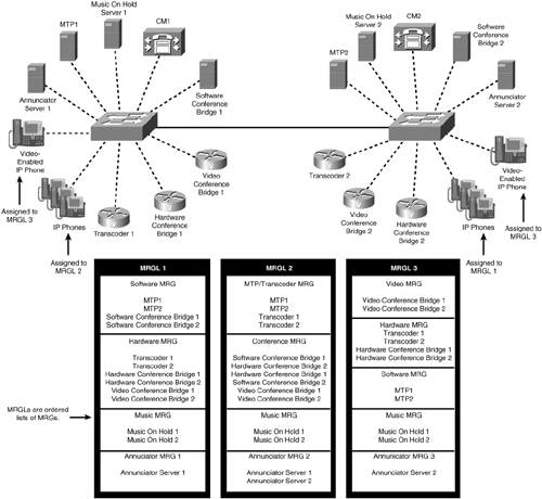
Resource allocation for IP Phones on CM1 (assigned to MRGL 2) is as follows:
- Conference allocation The phones on CM1 get a software conference resource or a hardware conference resource or a video conference resource. All conference resources in the cluster are allocated as a single pool of resources, and no distinction is made between them.
- MTP allocation All MTPs and transcoders in the cluster are allocated as a single pool of resources. There is no distinction made between them.
- Transcoder allocation Only transcoders are allocated when a transcoder is requested.
- MOH allocation Both MOH servers are used, and the load is spread across both of them.
- Annunciator allocation Both annunciator servers are used, and the load is spread across both of them.
Resource allocation for IP Phones on CM2 (assigned to MRGL 1) is as follows:
- Conference allocation The phones on CM2 always get a software conference bridge until there are no more software conference resources in the cluster. Then they get hardware conference resources or video conferences resources until software resources are available again. Software resources always have priority over hardware conference resources and video conference resources. There is no priority given to hardware conference resources over video conference resources. Both hardware and video resources are allocated as a pool of resources.
- MTP Allocation Software MTPs are allocated until there are no more software MTPs. Transcoders are allocated only when there are no software MTPs available. Software MTPs always have priority over transcoders.
- Transcoder allocation Only transcoders are allocated when a transcoder is requested.
- MOH allocation Both MOH servers are used, and the load is balanced across both of them.
- Annunciator allocation All annunciators are allocated from annunciator server 1. Annunciator server 2 is not available to phones on CM2.
Resource allocation for video-enabled IP Phones on CM1 or CM2 is the same, and is as follows:
- Conference allocation The video-enabled IP Phones on both CM1 and CM2 always allocate a video conference bridge if one is available. Then they get hardware conference resources until video conference resources are available again. Video resources always have priority over hardware conference resources.
- MTP allocation When an MTP is requested, transcoders are allocated until there are no more transcoders available. Software MTPs are then allocated until a transcoder becomes available. Transcoders always have priority over software MTPs.
- Transcoder allocation Only transcoders are allocated when a transcoder is requested.
- MOH allocation Both MOH servers are used, and the load is balanced across both of them.
- Annunciator allocation All annunciators are allocated from annunciator server 2. Annunciator server 1 is not available to video-enabled IP Phones.
The Order of Precedence for MRGL Assignments
Each endpoint device can have an MRGL associated with it. The two levels at which you can assign an MRGL are as follows:
- The device level
- The device pool level
When a CallManager needs a media resource for an endpoint during a call, CallManager requests a media resource of a specified type from the Media Resource Manager (MRM). The MRM finds the appropriate MRGL to use for that device by following the order of precedence, defined in Table 5-5.
|
Order of Precedence Levels |
Comments |
|---|---|
|
MRGL assigned to a device |
An MRGL assigned to a device applies only to that particular device. A media resource will be selected from the device's MRGL if one is assigned. If no resources of the requested type are available, it will then try to select a media resource from Null MRG. |
|
MRGL assigned to a device pool |
The MRGL assigned to a device pool applies to all devices that are in that device pool. This is the most general level at which an MRGL can be assigned. It will be used when there is no MRGL assigned at the device level. If no resources of the requested type are available, it will then try to select a media resource from the Null MRG. |
|
No MRGL assigned to the device pool or the device |
If neither of these two entities have an MRGL assigned, CallManager uses the Null MRG for all media resource allocations required. |
Media Resource Allocation Through Media Resource Manager
CallManager uses a simple two-step process to select a resource for a given allocation request once the MRGL is identified. Each step executes a simple algorithm. The interaction of these two algorithms makes control of the resource allocations very flexible.
The two-step allocation process is as follows:
|
Step 1. |
Get an MRG from the MRGL. |
|
Step 2. |
Find a resource within that MRG, if one is available. |
If the MRM finds an available resource of the specified type, it is returned to the requestor. If the selected MRG has no resources of the requested type, or the existing ones are not available, the MRM repeats this two-step sequence (perhaps multiple times) until either an available resource is found or all of the MRGs in the MRGL have been searched. Only if the MRM cannot find a resource of the specified type after searching all groups in the entire MRGL does it return an error indicating that no resources of that type are available.
Selecting an MRG from the MRGL
This algorithm selects and returns the next MRG from the list contained in the MRGL in priority order from top to bottom. The list is processed only once on each allocation request.
Selecting a Resource Within an MRG
Resources within an MRG are organized so that all resources of each given type are in a list together in the order presented in the MRG. In other words, it contains a set of lists, one for each type of resource that is present in that MRG.
This algorithm performs the following steps:
|
Step 1. |
Find the resource list for the type of resource requested. |
|
Step 2. |
When the list is found, allocate the next available resource using a next-available algorithm on the list. The next-available allocation begins at the point in the list where the previous allocation request ended and looks for the next resource in the list that is available. |
|
Step 3. |
If an available resource is found, allocate it and return it to the requestor. If one is not found, notify the MRM that one is not available in this MRG. |
Figure 5-10 illustrates the allocation order within an MRG. All resources are contained in the MRG. For calls that require a transcoder, the allocation order is illustrated. Note that they are allocated in next-available fashion.
Figure 5-10. Allocation Order Within an MRG for a Transcoder Request
Allocating a resource is accomplished by finding a device in the list that appears to have resources available. The device control process maintains the resource status for each device, so the MRM sends an allocation request to the device control process and attempts to allocate a resource. If one is available and the device status is good, a resource is allocated and returned to the MRM. If one is not available or the device status is bad (not available), the MRM is notified that no resource is available on that device. Figures 5-11, 5-12, and 5-13 illustrate this.
Figure 5-11. Normal Resource Allocation Sequence
Figure 5-12. Device Is Not Registered or Out of Service
Figure 5-13. Device Controller Has No Resources Available
Figure 5-11 shows the order of processing for resource allocation. The MRM gets a device name from the MRG and then sends a device look up request to the device manager. The device manager responds with the location of the device controller, whereupon the MRM sends an Allocation Request to the device controller. If the device controller has available resources, it responds with a Resource Allocation Response message, which is then returned to the requestor.
Figure 5-12 shows the allocation sequence when the first device is not registered. The MRM selects another device from the MRG and makes another request to the device manager. The sequence then proceeds normally.
Figure 5-13 shows the sequence when the device controller has no resources available for the device. In this case, the MRM must select another device from the MRG, request the location of the device controller, and then ask that device controller whether it has a resource. The device controller responds with a Resource Allocation Response, and the Resource Allocation Response is returned to the requestor.
When the MRM has exhausted the list of devices in the MRG and subsequently in the MRGL, it notifies the requestor that no resources of the requested type are available.
Tip
If you want the processing load for a given resource type spread across several media resource servers, put all media resource servers of a given type in the same MRG. Within a single MRG, a resource of a given type is allocated in a next-available fashion. This does not guarantee that it will spread the load evenly, but it will spread the load. If you want to force CallManager to allocate resources from the same server until no more resources are available on that server, you must put each resource server of the same type in a separate MRG, and organize the MRGs in the MRGL in the order that you want the resource servers used.
Organizing Resource Allocation Using MRGs and MRGLs
The resource allocation tools provided allow a great deal of flexibility in determining how CallManager allocates media processing resources. Several different arrangements are shown in this section. This is not an exhaustive set, but perhaps it is enough to spark some ideas and to help you understand how MRGs and MRGLs can be used effectively.
Figure 5-14 illustrates a possible arrangement of media resources within a CallManager cluster. In this example, different departments are homed on separate CallManager nodes. This arrangement forces phones in Sales to use resources from the Sales group, phones in Marketing to use resources in the Marketing group, and phones in Engineering to use resources in the Engineering group. In this case, the resources are registered with the same CallManager node as the phones and gateways. See Figure 5-15 for another possible arrangement.
Figure 5-14. Media Resource Group Cluster Overview
Figure 5-15. Media Resource Group System Overview
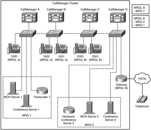
Figure 5-15 illustrates the fact that media resources are available throughout the cluster and do not have to be registered with the same CallManager from which they are used. All IP phones and the gateway in this figure have full access to media processing resources, even though in some instances the IP phones are registered to CallManager nodes that do not have any media processing resources registered to them. This arrangement still forces the IP phones on CallManagers A or B to use only resources from MRG1. The devices on CallManager C or D can use all resources, but they use the resources from MRG2 first. When those are exhausted, they can use the resources from MRG1.
Figure 5-16 illustrates a possible arrangement for restricting access to media processing resources.
Figure 5-16. Using an MRGL to Restrict Access to Media Resources
As shown, you can assign all resources to three groups (no resources are left in the default group). Create MRGL 1 and assign the three MRGs to it. Do not assign an MRGL at the device pool level. In the phone configuration, for the phones homed on CM1, do not assign an MRGL to them. These phones cannot use any media resources when they are configured this way because there are no resources available in the Null MRG and none available at the device pool level. Assign MRGL 1 to all the other IP phones. The other IP phones have access to all the resources.
You can use the same concept to restrict any particular device or type of devices from groups of users. For example, if you want to restrict phones on CM1 from using any conference resources, create another MRGL, and add the two MRGs without the conference resources to it. Assign the MRGL without conference resources to the phones on CM1. Now they cannot access conference bridges.
Cisco CallManager Architecture
- Cisco CallManager Architecture
- Circuit-Switched Systems
- Enterprise Deployment of CallManager Clusters
- Regions
- Summary
Call Routing
- Call Routing
- The Three Responsibilities of Call Routing
- The Seven Fundamentals of Call Routing
- Route Patterns and Route Filters
- Dialing Transformations
- Translation Patterns
- Call Hunting Constructs
- Calling Search Spaces and Partitions
- Case Studies
- Miscellaneous Solutions
- International Numbering Plans
- Troubleshooting
- Summary
Station Devices
- Station Devices
- Definition of Station Devices
- Overview of Station Device Features Supported by CallManager
- Overview of Station Devices Supported by CallManager
- SCCP Station Devices
- Cisco VT Advantage
- Computer Telephony Interface (CTI) Devices
- H.323 Endpoint Devices
- Summary
Trunk Devices
- Trunk Devices
- Architectural Overview of Trunk Devices
- Overview of Circuit-Switched Interfaces
- VoIP Gateway Security
- H.323 Gateways
- MGCP Gateways
- SIP
- Summary
Media Processing
- Media Processing
- Media Processing Overview
- Architecture and Functionality of the Media Control Layer
- Ad Hoc Conferencing
- Meet-Me Conferencing
- Summary
Manageability and Monitoring
Call Detail Records
- Call Detail Records
- Overview of CDR Data
- Creation and Usage of CDR Data
- Storage and Maintenance of CDR Data
- Understanding Field Data in CDRs
- Understanding Field Data in CMRs
- Identifying CDR Data Generated for Each Call Type
- Accessing CDR Data in the Central CDR Database
- Hints on Processing CDR Data
- Troubleshooting CDR Data Generation and Storage
- Summary
Appendix A. Feature List
Appendix B. Cisco Integrated Solutions
- Appendix B. Cisco Integrated Solutions
- Infrastructure Solutions
- Telephony Service Solutions
- Client Solutions
- Application Solutions
- System Tools
Appendix C. Protocol Details
- Appendix C. Protocol Details
- H.323 Signaling
- QSIG
- SIP Signaling
- SCCP Call Signaling
- Application Protocols
Index
EAN: 2147483647
Pages: 141
