Design Considerations
At this point, you should have a pretty good idea of how IPsec works at a high level as well as which topology your organization should probably deploy. This section of the chapter provides general design considerations that apply in some way to all of these topologies.
Platform Options
Platform options for security in general are discussed in Chapter 7, "Network Security Platform Options and Best Deployment Practices." Based on the information there and the unique requirements of IPsec, this section discusses some options for IPsec platform selection.
Site-to-Site IPsec Platforms
Often the most appropriate platform choice for site-to-site VPNs is to do your IPsec on a router. There are certainly situations in which a router might not be appropriate, as outlined in Chapter 7, but here's why the router is the best default choice.
If high availability is a requirement or your IPsec network is at all complex, you probably need dynamic routing. Even without a complex network, dynamic routing makes your VPN act more like a private network, greatly simplifying connectivity. As discussed later in this section, dynamic routing generally requires multicast traffic that doesn't function across IPsec links. IPsec as currently implemented and specified in the standards is unicast only. As such, the workaround is to encapsulate multicast traffic within a tunnel built using something like GRE. Although it is possible for an appliance to code this feature into the product, it can be found most easily in network devices (namely, routers). Likewise, if you need quality of service (QoS) on the edge of your network, a router is probably the best place to implement it.
WARNING
Remember from Chapter 7 that several characteristics of routers make them less than ideal for use in a security role. These still apply when considering them for an IPsec role. Configuration and management of the devices are key.
Remote User IPsec Platforms
For remote user VPNs, you have more flexibility because you are not running dynamic routing. For these users, an appliance, firewall, or router can be used, depending on the size of the network.
For example, a very small site might do its remote access and site-to-site on its sole access router to the Internet. A medium-size network might do site-to-site on a router, but separate its remote access to its firewall or a dedicated appliance. Larger networks will segment this access even further.
NOTE
For networks with a dedicated firewall, you probably don't want to implement IPsec on your WAN access router, but rather configure it on an IPsec-only device connected to your Internet edge. Specific designs for this are presented later in this chapter and in Chapter 13, "Edge Security Design."
Identity and IPsec Access Control
From an identity perspective, the most scalable solution is to use a AAA/OTP infrastructure using Xauth for remote user VPNs and digital certificates for all but the smallest site-to-site VPNs. For remote user VPNs, you are authenticating an individual, and as such, access control can be applied to that individual based on the user's group membership in the AAA server. For site-to-site VPNs, you are authenticating the device at the remote end, not the individual who initiated the traffic that started the IPsec SA setup. Just like a WAN connection, you are relying on the physical security and network access control at the remote site to ensure that only authorized individuals use the VPN.
The extent to which you can trust these remote locations factors in when considering any further access control for these connections.
Layer 3 IPsec Considerations
So far, you've examined IPsec basics, IPsec protocol considerations, topology choices, and platform options. Even after making many of these decisions, you still must consider other factors relating to IPsec and networking in general. These issues center around the following:
- Routing
- Network Address Translation (NAT)
- GRE
- IP addressing
Routing
Most of the routing information is covered earlier in the chapter. To summarize, in most cases you will benefit from dynamic routing. If you are migrating from a private WAN to a site-to-site VPN, use routing if you had it previously in your WAN. If your WAN was small enough that you used static routing, you can probably use static routes for your VPN as well. For remote user VPNs, you need only ensure that your central site has proper routing to the IPsec gateway terminating the remote user connections. The routing for the remote client is handled by the SPD and depends on the presence or absence of split tunneling.
Dynamic routing can be a great help while you are migrating from your private WAN to a VPN. You can bring up individual VPN links and make sure they work while still using the private WAN links. Then by just changing the routing metric, you can switch your traffic to the VPN link instead of the private WAN link. If there are any problems, you can just as easily switch your traffic back to the private WAN link while you troubleshoot problems with the VPN link.
NAT
NAT does some interesting things to IPsec, depending on the mode of operation. To begin with, NAT isn't necessary in most IPsec deployments whether they're site-to-site or remote user. Unfortunately, particularly with remote users, NAT sometimes exists and must be designed around. The next two sections outline NAT considerations in site-to-site and remote user VPNs.
Site-to-Site Considerations
In a traditional site-to-site network, each IPsec gateway usually requires a publicly routable IP address. This is because the negotiation between the two IPsec peers occurs over the public Internet. With RFC 1918 addresses on the inside of the gateway and routable addresses on the outside of the gateway, tunnel mode allows the 1918 addresses to traverse the Internet to your remote sites without modification. This is a typical site-to-site design and is shown in Figure 10-16.
Figure 10-16. Typical RFC 1918 IPsec
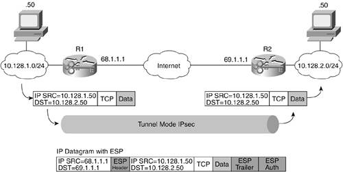
Because AH signs the entire packet (Figure 10-3), it is impossible to use with NAT. Because the outer IP header is not signed, ESP (Figure 10-4) can be used with NAT but only in one-to-one translations.
One-to-one translation means an IPsec gateway has a statically defined routable address that is used only for the gateway and does not come from a common pool. In this scenario, and when using ESP, NAT can work between the IPsec gateways. In Figure 10-16, if there were a NAT device (or two) between the IPsec gateways, the outer IP header could be modified by that NAT device and still allow IPsec to function properly. This works only if the IP address is not used in the ID field of the IKE authentication. This means you need digital certificates. Different vendors have workarounds for the one-to-one translation requirement for ESP, and this is an area of active development in the IETF.
Remote User Considerations
For remote users, relying on static NAT isn't an option. Too often, the remote user is in a location with unknown connectivity, often with many-to-one NAT. Unfortunately, many-to-one NAT doesn't work with IPsec. Here are just a few locations where many-to-one NAT might be used:
- Home broadband service
- Hotel Internet connections
- Connections from another organization through its Internet connection
The protocol standards for fixing this problem with many-to-one NAT are still being developed in the IETF. Check the IPsec Working Group for the latest information. For now, each IPsec vendor has its own method of solving this problem. Cisco Systems, for example, tunnels IPsec ESP packets inside of a UDP packet, which allows packets to cross a NAT device. In addition to this, the UDP source port for IKE is tracked by the gateway to ensure IKE functions properly. In normal situations, the source and destination ports for IKE are 500. With many-to-one NAT, this is not possible because source port modification is used by the NAT device to figure out which datagram goes to which host.
GRE
GRE is a method of tunneling traffic defined in RFC 2784. An alternate protocol, IP-within-IP defined in RFC 2003, does basically the same thing but does not support any protocol other than IP. GRE is widely used today and has a specific benefit for IPsec: GRE is capable of carrying multicast traffic over a unicast tunnel. This means that dynamic routing can be done using IPsec as an encryption option for the GRE traffic. The packet flow looks like this:
|
1. |
A packet arrives at the IPsec gateway. |
|
2. |
The gateway looks up the IP destination and sees that the destination is reachable by the GRE tunnel. |
|
3. |
The packets is fragmented if necessary and then encapsulated individually in GRE (which adds 24 bytes). |
|
4. |
Routing to the other side of the GRE tunnel is configured to use IPsec per the SPD configured on the peer. |
|
5. |
The GRE-encapsulated packet is encrypted with IPsec and sent to the other IPsec peer. (The IPsec packet might also need to be fragmented.) |
|
6. |
The reverse happens as the traffic is decrypted. |
TIP
When referring to this design that uses GRE and IPsec, it is appropriate to call it "GRE + IPsec" or "GRE over IPsec" but not "IPsec over GRE" (since IPsec is the final transport method).
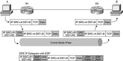
GRE + IPsec is one of the deployment methods discussed later in the chapter, and there you will be able to see what the configuration looks like in detail. GRE can also be used with routing as a form of high availability. This works by configuring an IPsec/GRE tunnel from a spoke to two different head-end central-site gateways. The preferred path can be chosen with routing protocol metrics. When one tunnel goes down, the second tunnel can continue to pass traffic. GRE + IPsec also exacerbates the fragmentation problem created by IPsec encapsulation because an additional 24-byte header is added on top of the ESP header. This effect is mitigated, though, because you are able to use transport mode IPsec instead of tunnel mode. Because you are already encapsulating the packet before IPsec, the IPsec flow is between only the two GRE endpoints, making transport mode possible. This eliminates the new IP header from tunnel mode, so the net increase is the 4 bytes used for the GRE identifier. This reduces the overall throughput of the IPsec VPN by a measurable amount (more so if you use tunnel mode + IPsec), but it is currently the only way to pass routing protocols that use multicast (OSPF, EIGRP on a Cisco router). Figure 10-17 shows the encapsulation details of GRE + IPsec.
Figure 10-17. GRE + IPsec
WARNING
Regarding GRE + IPsec, it might not always make sense to use transport mode instead of tunnel mode. If the IPsec hardware accelerators in your gateways are optimized for tunnel mode, you might be better off adding the extra 20 bytes. Check with your vendor for more details. Some hardware accelerators from Cisco, for example, are faster in tunnel mode.
One final consideration for GRE + IPsec is routing protocol scalability. Just like in a traditional WAN network, there is a limit on the number of routing peers that you can attach to each head-end device. Depending on the routing protocol you use and the unique characteristics of your network, that number is in the hundreds.
TIP
In a Cisco-only site-to-site deployment, EIGRP offers a mode called "EIGRP Stub" that greatly enhances the number of spokes that can be connected to any one peer. More information is available at the following URL: http://www.cisco.com/univercd/cc/td/doc/product/software/ios120/120newft/120limit/120s/120s15/eigrpstb.htm. Basic EIGRP is used in the GRE + IPsec configuration examples.
IP Addressing
Like any WAN deployment, it helps to have your IP address allocations easily summarized so that the entire site can be represented by a single IP address statement. In some networks, this is a possibility; in others (particularly larger networks), it is almost impossible without readdressing the entire network.
Fragmentation and Path Maximum Transmission Unit Discovery
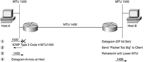
As you learned in Chapter 6, "General Design Considerations," fragmentation can be dealt with by allowing ICMP type 3 code 4 messages into your network. This allows a function called path MTU discovery (PMTUD) to function for TCP segments. End-host-to-end-host MTU negotiation occurs at the beginning of a TCP communication with the MSS option in the TCP header. This doesn't take into account differences in the path MTU, though, as introduced by different WAN MTUs. This is where PMTUD is useful. It is helpful to first see a basic example of fragmentation without IPsec: Figure 10-18 shows basic fragmentation as it occurs for UDP traffic and TCP traffic with the Don't Fragment (DF) bit not set; Figure 10-19 shows the same example with the host using PMTUD and setting the DF bit for all communications.
Figure 10-18. IP Fragmentation
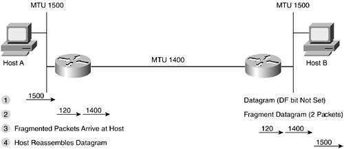
Figure 10-19. Basic PMTUD
When using GRE, it is just like the preceding example except the MTU is set to 1476 when the actual transmission media is 1500 (20 bytes for new IP header, 4 bytes for GRE encapsulation). GRE fragmentation occurs before encapsulation. PMTUD for the tunneled traffic (to catch lower MTU links along the path) is turned off by default on Cisco routers. You can enable it with the following command on the interface used by the tunnel:
Router(config-if)# tunnel path-mtu-discovery
When using IPsec, fragmentation occurs after encryption and PMTUD is on by default. If a packet arrives at the IPsec gateway and needs fragmentation but the DF bit is set, the gateway drops the packet and sends a type 3 code 4 message just as in traditional WAN fragmentation.
TIP
On Cisco routers, reassembly of fragmented IPsec packets is done in process mode as opposed to being Cisco Express Forwarding (CEF) switched. This can drastically reduce the forwarding speed of the decrypting router. For some platforms, starting primarily with the Cisco 12.2(13)T IOS release, Cisco introduced the "prefragmentation" feature for IPsec. This feature works by fragmenting a packet before it enters the IPsec process if the IPsec encapsulation would have required fragmentation after encryption. This ensures that the decrypting router does not have to reassemble the packet before decrypting it. Prefragmentation can be enabled with the following command run either system wide or for a specific interface:
Router(config)# crypto ipsec fragmentation before-encryption
If you are doing GRE + IPsec, you don't need this command. The same functionality is accomplished by lowering the ip mtu on the tunnel interface because GRE does fragmentation before encapsulation.
When transport mode ESP IPsec and GRE are combined, fragmentation can be fairly complex. Figures 10-20 and 10-21 show a packet with the DF not set and another with the DF bit set.
Figure 10-20. GRE + IPsec Fragmentation
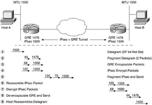
Figure 10-21. GRE + IPsec with PMTUD
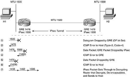
As you can see in Figure 10-21, IPsec transport mode ESP, for example, adds a maximum of 38 bytes to a packet for the ESP information. Tunnel mode adds a maximum of 58 bytes because of the new IP header.
Both of these numbers assume all the security options enabled for IPsec. Therefore, you can optimize your configuration to minimize the number of PMTUD rounds you must go through. Simply start your GRE tunnel with a default MTU of 1438 for transport mode or 1418 for tunnel mode. This ensures that, by the time the packet is fully encrypted, it will not need to be fragmented again.
Router(config)#interface Tunnel0
Router(config-if)#ip mtu 1438
Fragmentation has even more variations if you introduce an intermediary router with an MTU less than 1500. For this and many other fragmentation situations, consult the excellent Cisco TAC guide on fragmentation issues, "IP Fragmentation and PMTUD," at the following URL: http://www.cisco.com/en/US/tech/tk827/tk369/technologies_white_paper09186a00800d6979.shtml.
Firewall and NIDS Placement for VPNs
One of the interesting deployment decisions you must make regarding IPsec is one of access control. This includes access rights defined on the IPsec gateway and through the use of additional security controls in firewalls and NIDS. Because IPsec operates at Layer 3 (L3), it can carry any unicast IP traffic across the tunnel, nearly equaling the connectivity options of a user directly connected. This contrasts with a higher-layer VPN, which is typically built to support a small number of key applications (web, e-mail, and so on).
So, with the capability to run almost any application across the VPN, you must decide whether that is desirable. The basic question comes down to trust. Do you want to trust central-site users as much as VPN-connected users? The answer to this depends in large part on your security policy, but the following guideline should help.
The stronger the identity controls in your IPsec VPN, the greater your ability to trust remote users. Because of differences in digital certificate scalability, this can result in you trusting remote IPsec-connected sites more than dynamically connected remote IPsec users. Assuming you are using digital certificates for site-to-site IPsec and Xauth with OTP for remote user IPsec, you have a good foundation for a significant degree of trust in remote sites and users.
If you decide to fully trust these users, you can connect them directly to your network much like you would a private WAN link or modem pool. If, however, you decide to trust them a little bit less (which is my default answer), your topology will differ. The following two sections compare the considerations around access control in these two trust models.
Trusted IPsec Topology
Figures 10-22 and 10-23 show two variations of a topology in which the IPsec VPN is trusted and granted connectivity on par with internal users or privately connected WAN links. In both designs, site-to-site and remote user VPNs are combined onto the same gateway device, which is not appropriate in larger networks.
Figure 10-22. Trusted IPsec Topology
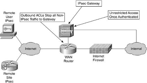
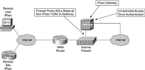
Figure 10-23. Trusted IPsec Topology (alternative)
As you can see, these are two variations on the same theme. In Figure 10-22, traffic to the IPsec gateway is diverted off of the WAN router after passing an ACL check ensuring that the traffic is IPsec. Remember that if you are using some sort of UDP or TCP encapsulation, to allow remote users to cross a NAT device you must allow this traffic in addition to IKE (UDP 500) and ESP (IP 50). After authentication and decryption, the traffic is passed directly to the internal network with no upper-layer filtering.
Figure 10-23 changes this only slightly by routing the IPsec traffic from a dedicated interface on the firewall into the internal network. Either design fulfills the connectivity goal. The firewall doesn't provide any added security. Because the traffic is encrypted, there is no real value the firewall can provide that an ACL can't, save one: to detect attacks against the IPsec gateways, you can audit the access control logging information. By filtering at the firewall, this data can easily be collected without having to view the information from another source. Still, you should audit the information from your Internet edge router anyway (for other security events), so this benefit is marginal.
WARNING
Because the IPsec users are fully trusted, there is no access control or intrusion detection system (IDS) after decryption. This means, if that trust was unfounded, remote IPsec connections would have direct access to your internal network with no easy point of audit or intrusion detection.
Semitrusted IPsec Topology
A more conservative IPsec topology is shown in Figures 10-24, 10-25, and 10-26. Again, a medium-size network is assumed.
Figure 10-24. Semitrusted IPsec Topology
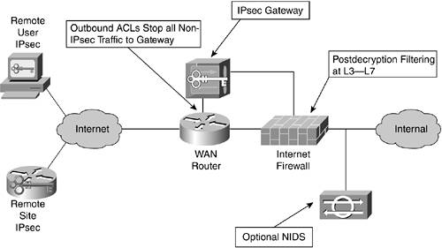
Figure 10-25. Semitrusted IPsec Topology (Alternative)
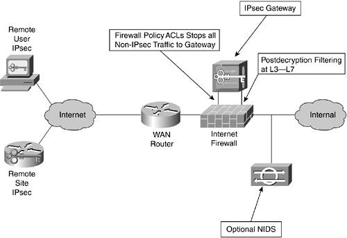
Figure 10-26. Semitrusted IPsec Topology: Integrated Firewall
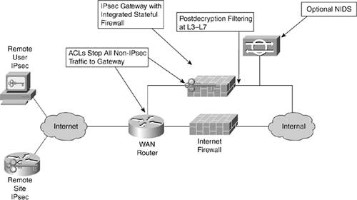
Figure 10-24 shows the main difference in the semitrusted topology when compared to trusted: traffic is routed into a firewall after decryption. This allows you to define the applications that can be run by remote IPsec connections in the same way that you can restrict the access for Internet users into your private network.
One policy around this limited access might provide only web and e-mail but not SSH or Telnet. For most organizations, however, this level of restriction is not appropriate for the general user population. For remote access, you are better off denying specific applications dictated by your policy and then permitting everything else.
In addition to providing restrictions on applications and services, the firewall acts as an audit point as well as an enforcement point for NIDS. By logging access at the firewall, you can have consistent access records of the communications initiated by your remote users. As discussed in Chapter 7, NIDS has particular issues when used to prevent a security violation through TCP resets or shunning. These issues are lessened when run against your internal users. Accidentally blocking an employee who triggered a NIDS alarm is a lot less costly than accidentally blocking a paying customer.
Figure 10-25 shows the same design modified to allow all traffic to flow into and out of two interfaces on the same firewall. You might prefer this design to the one in Figure 10-24 for the same reasons you might prefer the design in Figure 10-23 to the one in Figure 10-22.
The design in Figure 10-26 differs because the firewall functionality is integrated into the IPsec gateway. Assuming this is easy to configure and manage, this can be an attractive alternative to using the corporate firewall for VPN users. In some cases, though, you must firewall more than just IPsec traffic from remote users. You might have traditional dial-in, additional VPN devices, or WAN connections. In these cases, it is more appropriate to use a dedicated firewall to aggregate all of these remote access methods, as shown in Figure 10-27.
Figure 10-27. Centralized Remote Access Firewall
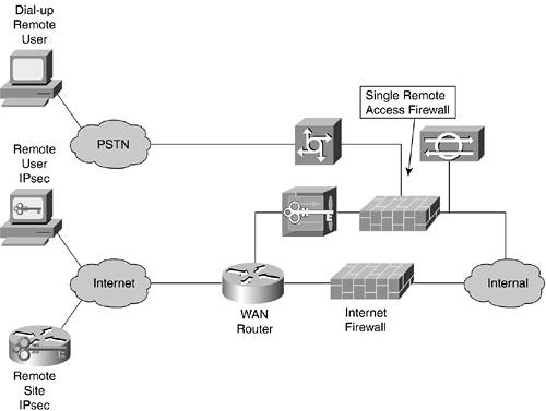
This kind of a design is further discussed in Chapter 13.
WARNING
Make sure you don't terminate your IPsec tunnels and then route them through the same firewall interface as external users accessing your network from the Internet. In this case, traffic on the same segment will be both trusted internal traffic (the decrypted IPsec flows) and untrusted external users. This severely handicaps your filtering options and leaves your VPN traffic subject to attack by outsiders.
High Availability
There are no direct provisions within the IPsec standards regarding HA. As such, vendors have implemented their own proprietary solutions to this problem. There are four potential methods of implementing IPsec HA:
- Hot standby Failover sessions using a protocol like Virtual Router Redundancy Protocol (VRRP) or Hot Standby Routing Protocol (HSRP).
- Stateful hot standby Failover sessions using one of the preceding protocols and transferring the IPsec state information from one device to another.
- Round robin Most common in remote user configurations giving a list of gateways to the client, which it tries in succession in the event the first fails.
- Routing convergence Configure IPsec links to multiple head-end devices using GRE tunnels and dynamic routing. In the event of a failure, the other IPsec tunnel will be used as fast as the routing protocol can converge. Because routing is used, each IPsec gateway need not be located in the same facility; routing can be used to determine through which gateway to route the traffic.
The first three options can be combined with some sort of load-balancing mechanism to make the best use of your deployed hardware. The routing convergence option can also be deployed in a load-balancing manner by dividing up the primary and secondary tunnels to different head-end devices, as shown in Figure 10-28.
Figure 10-28. Load-Balanced Site-to-Site Routed IPsec Design
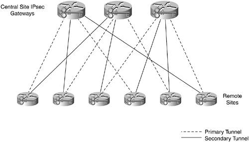
Here you can see that each of the three devices has exactly one third of the primary tunnels and one third of the secondary tunnels. This way, in the event of a head-end failure, the other two running gateways each can pick up half of the failed gateway's load. Managing this configuration can be difficult because tracking which remote branch should terminate on which central-site device gets very difficult as the number of central-site devices increases.
The first three HA options are primarily useful for remote user connections because they don't use routing. If your network is large enough that you need HA, you probably need routing, which will steer you toward the routing convergence option for your site-to-site networks.
NOTE
HSRP IPsec designs are not detailed in this book. As a strong advocate of routing for your VPN, I recommend GRE + IPsec for almost all IPsec site-to-site designs. If you are interested in HSRP IPsec, see the following URL: http://www.cisco.com/en/US/tech/tk583/tk372/technologies_tech_note09186a00800942f7.shtml.
QoS
Although this book doesn't cover QoS tools, it is important to point out where IPsec can intersect with QoS. QoS considerations around IPsec are varied. Depending on the application you are running, you might need differentiation of tunneled traffic or specific traffic within the tunnel. In general, QoS functions can be run on IPsec just like any other traffic. The key is to ensure that any QoS classification occurs before the packet is encrypted so that its priority is maintained.
Most IPsec implementations copy the type of service (TOS) bits from the IP header to the outer header in IPsec tunnel mode. This allows traffic, which has been classified prior to IPsec encryption, to have that same marking on the IPsec IP header between the IPsec endpoints.
If you are trying to classify traffic on the same device as you encrypt it, you might need a feature in Cisco IOS called qos pre-classify. This command enables classification of packets to occur before IPsec.
Most often, QoS requirements dictate the service level agreements (SLAs) you need from your SPs. If you don't know the target round-trip delay on an SP's network, it is impossible to determine whether the IPsec will put you over that delay budget. When two IPsec remote peers are on different SP networks, this creates additional headaches because often SLAs are difficult to achieve between service providers. From a design standpoint, there are three potential QoS situations to be aware of when deploying IPsec:
- Delay/bandwidth-sensitive application Applications such as IP telephony cannot deal with excessive delays. If you are running IP telephony over IPsec, you certainly must consider the IPsec process when calculating the delay budget for the IP telephony calls. By prioritizing IP telephony traffic over other VPN traffic, you can ensure that it gets preferential treatment as it passes through the crypto process and out to the SP.
- Power user resource starvation When setting up a remote user VPN, you might wish to limit the amount of bandwidth any one user can consume on the IPsec gateway. A broadband-connected user could consume a significant percentage of your overall gateway capacity if you aren't careful. Rate limiting generally occurs on the IPsec gateway and puts an upper limit on the total bandwidth each user can consume.
- Internet WAN link starvation When migrating from a private WAN to IPsec, keep in mind that you must augment your Internet capacity to allow for all the remote site's traffic. If you aren't careful, your other applications, such as your web server and e-mail system, might suddenly find themselves starved for bandwidth. This can also happen to the Internet link of a remote site because it often has far less bandwidth than the central site.
IPsec Vendor Interoperability
For most networks, IPsec interoperability doesn't come into play because the IPsec solution is sourced from a single vendor. In extranet environments, however, IPsec interoperability can become quite an issue. A few things affect interoperability in IPsec implementations:
- The technology isn't quite mature. Although certainly not completely new, getting two VPN gateways to talk IPsec isn't quite as simple as getting two RIP routers to talk to one another.
- Even if the technology were mature, IPsec is complex, which leads to issues in implementation.
- Because the vast majority of VPNs are single vendor, there is no motivation to solve all interoperability problems as would be present in the case of a more pervasive protocol like BGP or DNS.
- The specifications do not meet the feature requirements of the organizations deploying IPsec. This has lead many vendors to implement prestandard functions to meet customer needs.
In general, interoperability is better for site-to-site VPNs than remote user VPNs. With remote user, there is a greater likelihood of proprietary extensions preventing one vendor's client from connecting to another vendor's gateway.
I expect IPsec vendor interoperability to get better over time, but it might be a number of years before interoperability is pervasive and problem free.
Part I. Network Security Foundations
Network Security Axioms
- Network Security Axioms
- Network Security Is a System
- Business Priorities Must Come First
- Network Security Promotes Good Network Design
- Everything Is a Target
- Everything Is a Weapon
- Strive for Operational Simplicity
- Good Network Security Is Predictable
- Avoid Security Through Obscurity
- Confidentiality and Security Are Not the Same
- Applied Knowledge Questions
Security Policy and Operations Life Cycle
- Security Policy and Operations Life Cycle
- You Cant Buy Network Security
- What Is a Security Policy?
- Security System Development and Operations Overview
- References
- Applied Knowledge Questions
Secure Networking Threats
- Secure Networking Threats
- The Attack Process
- Attacker Types
- Vulnerability Types
- Attack Results
- Attack Taxonomy
- References
- Applied Knowledge Questions
Network Security Technologies
- Network Security Technologies
- The Difficulties of Secure Networking
- Security Technologies
- Emerging Security Technologies
- References
- Applied Knowledge Questions
Part II. Designing Secure Networks
Device Hardening
- Device Hardening
- Components of a Hardening Strategy
- Network Devices
- NIDS
- Host Operating Systems
- Applications
- Appliance-Based Network Services
- Rogue Device Detection
- References
- Applied Knowledge Questions
General Design Considerations
- General Design Considerations
- Physical Security Issues
- Layer 2 Security Considerations
- IP Addressing Design Considerations
- ICMP Design Considerations
- Routing Considerations
- Transport Protocol Design Considerations
- DoS Design Considerations
- References
- Applied Knowledge Questions
Network Security Platform Options and Best Deployment Practices
Common Application Design Considerations
- Common Application Design Considerations
- DNS
- HTTP/HTTPS
- FTP
- Instant Messaging
- Application Evaluation
- References
- Applied Knowledge Questions
Identity Design Considerations
- Identity Design Considerations
- Basic Foundation Identity Concepts
- Types of Identity
- Factors in Identity
- Role of Identity in Secure Networking
- Identity Technology Guidelines
- Identity Deployment Recommendations
- References
- Applied Knowledge Questions
IPsec VPN Design Considerations
- IPsec VPN Design Considerations
- VPN Basics
- Types of IPsec VPNs
- IPsec Modes of Operation and Security Options
- Topology Considerations
- Design Considerations
- Site-to-Site Deployment Examples
- IPsec Outsourcing
- References
- Applied Knowledge Questions
Supporting-Technology Design Considerations
- Supporting-Technology Design Considerations
- Content
- Load Balancing
- Wireless LANs
- IP Telephony
- References
- Applied Knowledge Questions
Designing Your Security System
- Designing Your Security System
- Network Design Refresher
- Security System Concepts
- Impact of Network Security on the Entire Design
- Ten Steps to Designing Your Security System
- Applied Knowledge Questions
Part III. Secure Network Designs
Edge Security Design
- Edge Security Design
- What Is the Edge?
- Expected Threats
- Threat Mitigation
- Identity Considerations
- Network Design Considerations
- Small Network Edge Security Design
- Medium Network Edge Security Design
- High-End Resilient Edge Security Design
- Provisions for E-Commerce and Extranet Design
- References
- Applied Knowledge Questions
Campus Security Design
- Campus Security Design
- What Is the Campus?
- Campus Trust Model
- Expected Threats
- Threat Mitigation
- Identity Considerations
- Network Design Considerations
- Small Network Campus Security Design
- Medium Network Campus Security Design
- High-End Resilient Campus Security Design
- References
- Applied Knowledge Questions
Teleworker Security Design
- Teleworker Security Design
- Defining the Teleworker Environment
- Expected Threats
- Threat Mitigation
- Identity Considerations
- Network Design Considerations
- Software-Based Teleworker Design
- Hardware-Based Teleworker Design
- Design Evaluations
- Applied Knowledge Questions
Part IV. Network Management, Case Studies, and Conclusions
Secure Network Management and Network Security Management
- Secure Network Management and Network Security Management
- Utopian Management Goals
- Organizational Realities
- Protocol Capabilities
- Tool Capabilities
- Secure Management Design Options
- Network Security Management Best Practices
- References
- Applied Knowledge Questions
Case Studies
- Case Studies
- Introduction
- Real-World Applicability
- Organization
- NetGamesRUs.com
- University of Insecurity
- Black Helicopter Research Limited
- Applied Knowledge Questions
Conclusions
- Conclusions
- Introduction
- Management Problems Will Continue
- Security Will Become Computationally Less Expensive
- Homogeneous and Heterogeneous Networks
- Legislation Should Garner Serious Consideration
- IP Version 6 Changes Things
- Network Security Is a System
References
Appendix A. Glossary of Terms
Appendix B. Answers to Applied Knowledge Questions
Appendix C. Sample Security Policies
INFOSEC Acceptable Use Policy
Password Policy
Guidelines on Antivirus Process
Index
EAN: 2147483647
Pages: 249
