UTP Noise and Interference
There are six major sources of noise and interference in a high-speed UTP system:
- Far-end reflections
- Near-end reflections
- Near end crosstalk ( NEXT )
- Alien crosstalk
- Far-end crosstalk (FEXT)
- Radio-frequency interference (RFI)
8.3.1 UTP: Far-End Reflections
When you launch power into a transmission system, three things can happen to it:
- Part of the power is absorbed by the transmission medium as the signal propagates.
- After a one-way propagation delay, part of the power is delivered to the load.
- The remaining power reflects from the load or from intermediate imperfections within the transmission line, and then bounces around within the cable until it is dissipated by mechanism (1) or (2).
In any reasonable signal transmission channel, only a tiny fraction of the signal power leaks out of the cable system in the form of radiation. As far as the integrity of the received signal is concerned , this amount of lost power is insignificant. It may cause some significant EMI headaches , but it's not large enough to worry about when computing the amplitude or shape of the received signal.
Portions of the original transmitted power that bounce around within the cable, arriving later at the far-end load are called far-end reflections (Figure 8.10). In a modern UTP data transmission system, because the one-way cable delay greatly exceeds the data baud period, reflections from one baud typically arrive at the receiver during the reception of some later baud. The far-end reflections are therefore not correlated with the data in the current received baud period and constitute a source of random noise to the receiver at the far end of the cable. This section examines the magnitude of far-end reflected noise.
Figure 8.10. One-half of 10BASE-T link showing unidirectional data transmission on one pair of UTP.
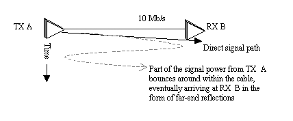
The magnitude of the far-end reflected signal shown in Figure 8.10 depends in part on the characteristic impedance of the cable. The characteristic impedance of data-grade UTP is controlled to within 15% for category 3 and 10% for higher categories (Table 8.1).
At the bitter ends of the cabling where the wiring meets your transceiver, a reflection always occurs due to the inevitable mismatch between the cable impedance and the input (or output) impedance of your hardware. With some hard work, you can control the input (or output) impedance of your circuitry to within about ±5%. The worst-case reflections occur when your transceiver impedance is high and the cable is low (or vice versa). Assuming a +5% transceiver impedance and a “15% category 3 UTP cable impedance, the total impedance mismatch is on the order of 20%, which generates about a 10% reflection [68] . If you have terminated the cable at both ends , the worst-case round-trip reflection would in that case be only 10% of 10%, amounting to only 1% of the transmitted signal amplitude not counting the additional round-trip of cable attenuation suffered by the reflected signal. Such a scenario illustrates the big benefit of terminating a cable at both ends ”each round-trip reflection is attenuated twice .
[68] A transceiver impedance of 105 ohms coupled to a cable impedance of 85 ohms generates a reflection of size (85 - 105)/(85 + 105) = “0.105 times the height of the incoming signal.
A complete reflections budget needs to take into account not only the reflections at the ends of the cable, but also those that occur in the middle. Wherever a transition occurs from one cable to another, there exists the chance that one cable will have a high impedance and the other a low impedance. When working with category 3 or 5 UTP, reflections from major cable transition points have a maximum amplitude of 15%, [69] provided that the lengths of cable on either side of the transition are sufficiently long to build up a full-scale reflection amplitude. The relation between the length of cable required to build up a full- sized reflection and the signal risetime is given approximately by
[69] A cable impedance of 85 ohms coupled to a cable impedance of 115 ohms generates a reflection of size (115 - 85)/(115 + 85) = 0.15 times the height of the incoming signal.
Equation 8.5

|
where |
cables of length l full (m) generate a full-sized reflection, |
|
t r is the signal 10% to 90% risetime (or fall time) in s, and |
|
|
v is the cable propagation velocity, m/s. |
Cables shorter than the critical length l full generate smaller reflections, in proportion to their length. For example, suppose you were working with a Nyquist band -limited system operating at 25 Mbaud on a cable with velocity v = 0.6 c . The risetime for such a system approximately equals the bit period of 40 ns. The critical length l full for this link is therefore l full = (40 ·10 “9 s)(0.6 ·2.998 ·10 8 m/s)/2 = 3.6 m. In this type of link, cables shorter than one meter won't generate much of a reflection even if their impedance mismatch is significant. Cables longer than 3.6 m, on the other hand, can easily produce noticeable reflections.
In a practical long-distance link, the worst-case magnitude of the far-end reflections must be limited by design. This is accomplished by establishing limits on the nominal cable impedance, the maximum variation of impedance within each cable, and the number of major transition points within each individual link. The number of transition points permitted in horizontal generic building wiring is four.
To compute the worst-case far-end reflection, you must sum all the second-order reflection modes. Figure 8.11 illustrates all the second-order reflection modes in a UTP connection with two transition points. [70] In the far-end received noise budget, all the worst-case second-order modes must be summed at the receiver.
[70] Transitions are usually accompanied by connectors.
Figure 8.11. Second-order reflection products for UTP connection.
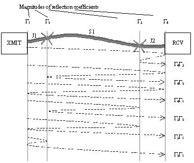
When estimating the worst-case reflection modes by hand, just sum the absolute values of the worst-case reflection coefficients at each transition point. [71] In addition, assume zero cable attenuation between transition points. For a more accurate answer, try using a mathematical calculation tool like MathCad, Mathematica, or MatLab to grind through all possible combinations of worst-case high and low impedances in each section of cable. Program the tool to check the total reflection noise and received signal intensity for each combination.
[71] In a slow data transmission system one might assume that two successive reflections, one positive and one negative, might average together during the period of one data symbol, rendering a worst-case effect that is less than the sum of absolute values. In a fast system where the reflections are each separated by more than one data symbol, it is possible to construct a data sequence that actually produces the worst-case sum-of-absolute-values effect.
The worst reflections usually result from transition points spaced apart by one-half data baud. Move the transition points closer, and the reflections tend to blur together, failing to attain peak worst-case values. Move the transition points further apart, and the reflected signals encouter additional round-trip cable attenuation. A spacing of about one-half data baud is the worst.
Connectors located at the cable transition points also generate their own reflections, which superimpose on the reflections due to changes in cable impedance. The magnitude of these reflections must be included in a good noise budget (see Section 8.4, "UTP Connectors").
Example Calculation of Far-End Reflected Noise Magnitude
Assume a system with cable impedances specified to within 100 W ± 10% and using both source and end terminations accurate to within 5%. Let there be one cable transition point located near each end of the cable (as in Figure 8.11).
The total cable attenuation between points is as follows :
J1 (short jumper )
“1 dB
S1 (long segment)
“10 dB
J2 (short jumper)
“1 dB
The assumed impedances are as follows:
Source
105 W
J1
85 W
S1
115 W
J2
85 W
End
105 W
The worst-case reflection coefficients are as follows:
G 1
“19.5 dB
G 2
“16.4 dB
G 3
“16.4 dB
G 4
“19.5 dB
The worst second-order, modes are as follows:
J1 S1 J2 G 4 J2 G 3 J2
“(1 + 10 + 1 + 19.5 + 1 + 16.4 + 1)
“49.9 dB
J1 S1 J2 G 4 J2 S1 G 2 S1 J2
“(1 + 10 + 1 + 19.5 + 1 + 10 + 16.4 + 10 + 1)
“69.9 dB
J1 S1 J2 G 4 J2 S1 J1 G 1... J1 S1 J2
“(1 + 10 + 1 + 19.5 + 1 + 10 + 1 + 19.5 ... + 1 + 10 + 1)
“75.0 dB
J1 S1 G 3 S1 G 2 S1 J2
“(1+10+16.4+10+16.4+10+1)
“64.8 dB
J1 S1 G 3 S1 J1 G 1 J1 S1 J2
“(1 + 10 + 16.4 + 10 + 1 + 19.5 + 1 + 10 + 1)
“69.9 dB
J1 G 2 J1 G 1 J1 S1 J2
“(1 + 16.4 + 1 + 19.5 + 1 + 10 + 1)
“49.9 dB
Worst-case total (sum of magnitudes )
“42.2 dB
The signal-to-noise ratio (SNR) at the far-end receiver is as follows:
Signal: J1 S1 J2
“(1 + 10 + 1)
“12 dB
Noise
“42.2 dB
SNR
30.2 dB
POINTS TO REMEMBER
- A complete noise budget takes into account all reflections within a cabling system.
- Connectors generate reflections that superimpose on the reflections generated by changes in cable impedance.
8.3.2 UTP: Near-End Reflections
When you shout into a tunnel, it echoes back. The same thing happens when you blast a high-speed digital signal into a long UTP cable: You get an echo. The term near-end reflection encompasses two different types of echo effects. The first echo effect is due to reflections that occur at cable transition points, termination points, and connectors. The other echo effect is specified by cable return loss (RL). It has to do with reflections generated due to imperfections within the cable itself.
The return loss specifications are important in systems that attempt to transmit in both directions ( full-duplex ) at the same time on the same pair of conductors.
In a unidirectional link the near-end reflections are of no consequence, because when you are transmitting on one conductor pair, you are not also listening to that same pair. Bidirectional, full-duplex systems are different. In a bidirectional, full-duplex link you are listening on the same pair with which you are transmitting. In that case you hear your own echo.
Figure 8.12 shows an example of a bidirectional, full-duplex data link. This link was designed by ROLM in 1983 as the basis of its digital telephones. The ROLM link sends two-level PAM data at 256 Kbaud in each direction. Data are sent continually at all times, in both directions, on a single pair of a category 3 cable. Partly because the data rate was so slow, echo problems on this link were easily managed. The ROLM system used a hybrid circuit (see Section 8.3.3 "UTP: Hybrid Circuits") to enable reception of the far-end signal even while the local transmitter was broadcasting.
Figure 8.12. A ROLM digital telephone transceiver transmits bidirectionally on a single pair of category 3 cable (circa 1982).
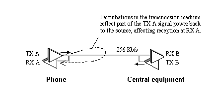
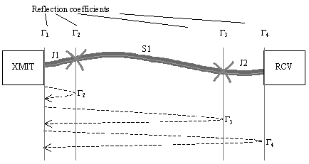
The noise reflected from cable transition points and connectors is qualitatively the same as far-end reflected noise, but quantitatively much more significant. The reason that near-end reflections matter so much in bidirectional systems is because the reflections in Figure 8.13 that arrive at RX A have bounced from only one reflecting body, as opposed to the reflections in Figure 8.11, which have each been attenuated by at least two bounces. The difference between the two situations is striking. The signal-to-noise ratio in the near-end case is much worse .
Figure 8.13. First-order reflection products for UTP connection.
Example: Near-End Reflected Noise Magnitude
Assume a system with cable impedances specified to within 100 W ± 10% and using both source and end terminations accurate to within 5%. Let there be one cable transition point located near each end of the cable (Figure 8.13).
The total cable attenuation between points is as follows:
J1 (short jumper)
“1 dB
S1 (long segment)
“10 dB
J2 (short jumper)
“1 dB
The assumed impedances are as follows:
Source
105 W
J1
85 W
S1
115 W
J2
85 W
End
105 W
The worst-case reflection coefficients are as follows:
G 1
“19.5 dB
G 2
“16.4 dB
G 3
“16.4 dB
G 4
“19.5 dB
The worst near-end reflection modes are as follows:
J1 G 2 J1
“(1 + 16.4 + 1)
“18.4 dB
J1 S1 G 3 S1 J1
“(1 + 10 + 16.4 + 10 + 1)
“38.4 dB
J1 S1 J2 G 4 J2 S1 J1
“(1 + 10 + 1 + 19.5 + 1 + 10 + 1)
“43.5 dB
Worst-case total (sum of magnitudes)
“17.1 dB
The signal-to-noise ratio (SNR) at a near-end receiver is as follows:
Signal: J1 S1 J2
“(1 + 10 + 1)
“12 dB
Noise
“17.1 dB
SNR
(Signal - Noise)
5.1 dB
POINT TO REMEMBER
- Bidirectional links must tolerate near-end reflections.
8.3.2.1 UTP: (Structural) Return Loss
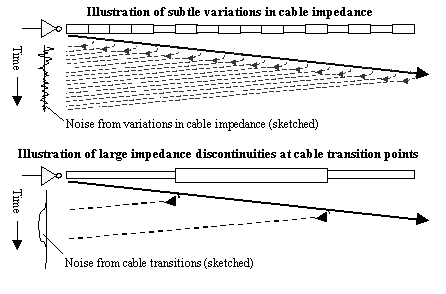
Compared to discrete reflections, the structural return effect is more complicated. Structural return noise results from minor variations in the characteristic impedance of a continuous cable. As a signal propagates down the cable, these minor variations create small reflections that propagate back towards the source. The composite of all the backwards -propagating signals is called structural return noise. This noise appears at the source as an almost Gaussian noise waveform. For sinusoidal inputs, the expected magnitude of the structural return noise for long cables varies in proportion to the 3/4-power of w . The faster you go, the larger the structural return noise becomes.
At higher frequencies the increase in structural return noise complicates the design of hybrid circuits. For example, some of the very early Ethernet UTP transceivers made by 3Com used a bidirectional architecture very similar to the ROLM system depicted in Figure 8.12. These early Ethernet transceivers operated bidirectionally at 10 Mb/s over category 3 UTP. The data rate per pair was higher than in the ROLM system by a factor of (10 MHz/256 KHz) = 39, making structural return loss problems significantly more worrisome (39 3/4 = 15.6 times more worrisome).
Structural return noise shares many similarities with the noise generated by reflections from cable transitions. Both are self-induced effects, meaning that the magnitude of either is proportional to the transmitted signal. If the transmitter ever shuts off, both effects diminish to near zero within one cable round-trip time.
Structural return noise is contributed from many, many small sources, all of which blur together into a continuously evolving waveform. The effect looks like white noise (except that the step response of the noise is precisely the same every time you measure it). Cable transitions, on the other hand, generate much larger, distinct, individual reflected signals punctuated by long gaps (Figure 8.14). Both noise sources contribute to the overall near-end noise budget at the receiver.
Figure 8.14. Time-space diagram showing qualitative difference between noise due to impedance variations and noise due to cable transition points.
Structural return noise is controlled for all generic building wiring types in one of two ways:
- A specification of structural return loss combined with a specification on the mean value of characteristic impedance (used for old category 3 cables), or
- A single specification of cable return loss (used for newer category 5e and 6 cables).
To understand the difference between these two specifications, imagine that characteristic impedance is a function that fluctuates as you progress along the length of a cable. The old structural return loss specification decomposes the characteristic impedance function into a mean value plus fluctuations. The term structural return loss refers only to the noise (in dB) reflected due to the fluctuations in impedance. Reflections due to the mean value of impedance are counted separately. When this form of specification is used, limits on the mean value of impedance are explicitly called out.
The newer term return loss assumes the cable is terminated into a perfect 100- W differential load. The noise (in dB) reflected under this 100- W load condition includes reflections from the fluctuations in impedance (structural return loss) plus other reflections due to errors in the mean value of impedance. The return loss therefore includes both the structural return noise and the mean value of characteristic impedance simultaneously instead of with distinct specifications. When a return loss specification is indicated, the nominal value of characteristic impedance is implied by the value of load resistance used in the test, but no explicit limits on the mean value of characteristic impedance are called out.
The TIA/EIA 568-B standard for categories 5e and 6 specifies return loss, as opposed to structural return loss, in order to circumvent problems associated with accurately defining and measuring the mean value of characteristic impedance (see Table 8.4). An overall noise budget calculation taking into account all forms of near-end reflections including cable return noise should be undertaken for any bidirectional full-duplex system.
Table 8.4. (Structural) Return Loss for UTP and 150- W STP-A Cabling (Worst Pair)
|
Cable type |
Freq. Range MHz |
Return loss dB |
|---|---|---|
|
cat-3 (structural return loss) |
1 10 |
12 12 “10log( f /10) |
|
cat-5e (return loss) |
1 10 20 |
20+5log( f ) 25 25 “7log( f /20) |
|
cat-6 (return loss) |
1 10 20 |
20+5log( f ) 25 25 “7log( f /20) |
|
150- W STP-A |
20 |
24 24 “10log( f /20) |
|
NOTES ”Values taken from TIA/EIA-568-B.2-2001 and TIA/EIA-568-B.2-1-2001. In all formulas, the frequency variable f is in MHz. |
||
POINTS TO REMEMBER
- A specification of structural return loss combined with a specification of the mean value of characteristic impedance is used for old category 3 cables.
- A single specification of cable return loss (as measured with the cable terminated in a 100- W load) simultaneously limits both the mean value and local perturbations in cable impedance.
8.3.2.2 Modeling Structural Return Loss
A transfer function representing the structural return effect may be modeled as a large number of separate little reflections, each with a frequency response proportional to w . The general form of the model looks like this:
Equation 8.6

|
where |
SRL ( w ) is a transfer function representing the structural return effect, |
|
w is the frequency of interest, rad/s, |
|
|
a n is a collection of independent, uncorrelated random variables |
|
|
H ( w , l ) is a transfer function representing a segment of cable l meters in length, as measured at frequency w , and |
|
|
D x is the length of each segment in the model, m. |
The model breaks the cable into N segments, each representing a small section of length D x . Each element in the sum represents the reflections due to the structural return effect from portion n . The term a n indicates the strength of the effect from segment n , which depends randomly on local impedance perturbations. When synthesizing a random SRL transfer function, a reasonable distribution to use for each a n is a Gaussian distribution with zero mean and standard deviation s . [72] In that case the standard deviation s should be set to produce the correct nominal amount of overall gain A at some frequency w , according to the following formula:
[72] The Greek letter sigma is used here to refer to the standard deviation of a random process, not conductivity.
Equation 8.7

The term j w in equation [8.6] indicates that the basic effect within each segment is a differentiating effect. This comes about due to the geometry of each segment. Imagine a single segment in isolation, coupled to an otherwise ideal, infinite cable. Let the segment in question have an impedance uniform over its length, but different from the characteristic impedance of the remainder of the cable. The imperfect segment will induce two impedance discontinuities, one at either of its ends, with opposite reflection coefficients (that is, one reflection will be negative and the other positive). The essence of the reflection effect is this: As the main signal steps into the perturbed area, a reflection will be generated, and as the main signal passes back out, a second reflection roughly equal in magnitude but opposite in sign to the first will be generated. The result is a pair of small, closely spaced impulses with opposite polarities. If the delay represented by each segment in the above model represents much less than the rise (or fall) time of the signals involved, the structural return operation at each segment looks very much like a derivative.
The term H ( w ,2 n · D x ) indicates that the total path traversed by the reflection from segment n includes the distance n · D x from the driver to segment n followed by an identical distance n · D x on the way back.
The attenuation predicted by this model at any particular frequency w is a random variable whose magnitude obeys the Rayleigh distribution. When the nominal gain is set to value A (this sets the average reflected power to a value of A 2 times the incoming signal power), the actual gain may vary considerably from trial to trial above and below this value. If it is your intention to generate a model whose worst-case gain just touches some specified limit for SRL, you should de-rate A by anywhere from 6 to 12 dB before using equation [8.7] to calculate an appropriate standard deviation. A de-rating factor of 8 dB was used to generate the synthetic NEXT curves in Figure 8.21.
Alternately, if you are casting random SRL functions for use in Monte-Carlo testing, you may individually adjust each function to guarantee that it just grazes the specified limit in at least one location.
If the function H ( w , l ) represents a skin-effect-limited channel, then the SRL noise modeled by these equations displays a 3/4-power law dependence on frequency (i.e., the noise grows at a rate of 15 dB per decade ).
POINTS TO REMEMBER
- Structural return noise is modeled as a summation of many noise sources with random amplitudes.
- Structural return noise grows at a rate of 15 dB per decade.
8.3.3 UTP: Hybrid Circuits
The circuit that makes possible bidirectional full-duplex transmission is called a hybrid circuit . Figure 8.15 illustrates a simple hybrid circuit appropriate for use on a single-ended transmission medium.
Figure 8.15. A hybrid circuit subtracts half the transmitted signal from the received signal to form a remainder equal to the desired signal from the far end.
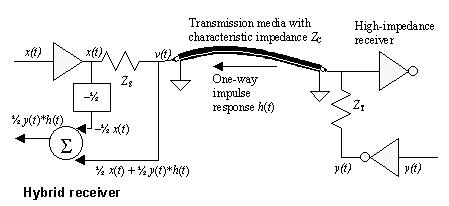
The waveform at v ( t ) is a superposition of effects from both sides. Mathematically, it is a linear combination of the signal x ( t ) and the signal y ( t ). Setting y ( t ) momentarily to zero, you may evaluate the gain from x ( t ) to v ( t ) using the voltage-divider equation.
In general these equations are pretty hairy, but they can be simplified in a major way by carefully designing impedance Z S to match Z C . Under that assumption the gain from x ( t ) to v ( t ) would be precisely 1/2. Similarly, the gain from y ( t ) to v ( t ) is also 1/2, but with an extra term included to account for the propagation loss in the transmission media.
Mathematically, the propagation effect is the equivalent of convolving the signal y ( t ) with the impulse response h ( t ) of the transmission line, leading to a fairly simple composite form for the waveform at v ( t ):
Equation 8.8

|
where |
the symbol * represents the convolution (linear filtering) operator. |
This last expression indicates that the signal at v is composed of two parts : one half the signal y ( t ) you wish to receive, modified by its passage through the intervening cable segment, plus a pesky interfering signal (1/2) · x ( t ). The beauty of the hybrid concept is that you can predict and therefore eliminate the pesky interfering signal by simply subtracting from the received waveform v ( t ) the known interfering quantity (1/2) · x ( t ). The summation block in Figure 8.15 subtracts (1/2) · x ( t ) from v ( t ), producing a final waveform equal to (1/2) · y ( t )* h ( t ). All hybrid circuits work on the same general principle ”they subtract from the received signal the known (or measured) interference from the transmitter.
Notice that the circuit gain from y ( t ) to v ( t ) is in the best of cases no greater than 1/2. This loss of 6 dB is a consequence of using what amounts to a double-end termination scheme.
The hybrid doesn't rid the circuit of the effects of h ( t ), but at least it eliminates interference from local transmissions. This technique is widely used to construct bidirectional full-duplex links.
The effects of h ( t ), if objectionable , must be reversed by an equalizing circuit. The equalizing circuit may either predistort the waveform y ( t ) to account for the assumed degree of distortion present on the cable or post-filter the resulting v ( t ) to restore the original waveform, or a little of both.
Let's review the conditions necessary for the proper operation of the hybrid:
- Foreknowledge of the transmission line impedance.
- End-termination with impedance Z T = Z C at all frequencies.
- Source-termination with impedance Z S = Z C at all frequencies.
If the termination impedances do not match Z C , then the gain from x ( t ) to v ( t ) will differ from 1/2 and the cancellation will not function properly. The same hybrid circuit is typically used at both ends of the line.
Hybrid circuits are rated in terms of the amount of the locally transmitted signal that leaks through the cancellation circuit to affect the hybrid output. This leakage is called the hybrid return loss. The hybrid return loss is reported in units of dB relative to the nominal gain of the received signal, which is usually 1/2. The hybrid loss is a function of the transmission-line impedance and the impedance of the terminations at both source and far ends of the transmission line.
It is instructive to examine the sensitivity of the hybrid circuit to various parameters.
A hybrid circuit's sensitivity to perturbations in the source impedance is approximately 1/2, meaning that a 10% change in the source impedance results in a 5% relative error at the output of the hybrid (26 dB return loss). The sensitivity to perturbations in the far-end termination impedance is similar.
The hybrid circuit in Figure 8.15 is designed to operate in a low-loss mode (LC mode or above), for which the characteristic impedance of the transmission line maintains a fairly constant real value Z C over the frequencies of interest. What if the line were operated in the dispersive RC mode? In that mode the characteristic impedance changes substantially with frequency. Matching Z S and Z T to Z C ( w ) for a dispersive line can become a serious challenge.
Figures 8.16, 8.17, and 8.18 explore that challenge. Each figure plots the input impedance Z IN ( w ) of a loaded transmission line versus frequency for several situations. The dotted lines reveal the characteristic impedance Z C ( w ) of the transmission line. This is the input impedance you would measure if the line were of infinite extent (or perfectly terminated). The real part of Z C appears in the top half of each figure, while the imaginary part (always negative) appears in the bottom half. The dotted-line plot for each figure is the same, representing the characteristic impedance of a normalized RC transmission line with per-unit-length parameters R = 1, L = 1, and C = 1.
Figure 8.16. With a simple resistive termination at the far end, the precise input impedance of the terminated transmission line varies as a function of the transmission-line length. It is therefore impossible to build a perfect (nonadaptive) hybrid circuit that works at all lengths and all frequencies using a simple resistive termination.
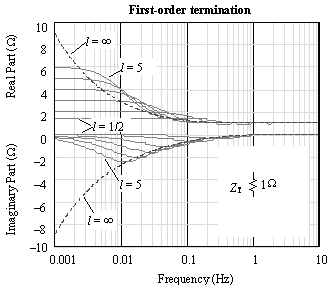
Figure 8.17. A second-order termination circuit improves the stability of the input impedance function at frequencies down to 0.1 Hz.
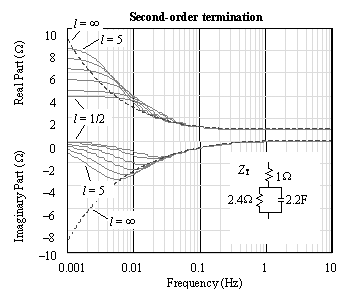
Figure 8.18. A third-order termination circuit stabilizes the input-impedance function at frequencies down to 0.02 Hz.
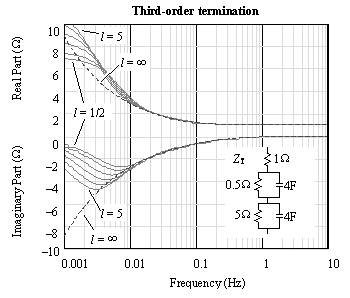
The solid lines in each figure depict the actual input impedance of normalized transmission lines of various lengths with particular end terminations. The lengths selected are 1/2, 1, 2, 3, 4, and 5 units.
Figure 8.16 illustrates the consequences of terminating an RC line with a simple resistance, in this case Z T = 1 W . This figure reveals an input impedance in the area above 1 Hz holding flat at 1 W . That's because the line is operating at those frequencies mostly as a low-loss, or LC, transmission line, for which the characteristic impedance equals  , a value that does not much change with frequency. Since the low-loss line is properly terminated in its characteristic impedance of 1 W , the reflection coefficient at the far end is zero and the input impedance Z IN does not vary with line length. It stays at 1 W .
At low frequencies the input impedance of finite-length, 1- W terminated RC transmission line varies dramatically with both frequency and lne length. For example, at DC the input impedance equals the far-end termination resistance (1 W ) plus the DC resistance of the line itself. In Figure 8.16 the series resistance of the line is 1 W per unit length, so for lengths of 1/2, 1, 2, 3, 4, and 5 units, the total DC resistance (line plus load) shown at the left side of the figure reads 1.5, 2, 3, 4, 5, and 6 ohms.
For this normalized transmission line, a hybrid constructed with source and load impedances of 1 W would function down to a frequency of approximately 1 Hz, below which the hybrid return loss would become unacceptably large.
You may generalize this rule for a resistively terminated hybrid, saying that the circuit only works above a cutoff frequency f = R / L (Hz), where R and L are the per-unit-inch values of resistance and inductance in the transmission line.
One exception to this generalized rule happens if the line is short enough compared to the frequencies of operation to be considered a simple lumped-element circuit. In that case the hybrid circuit at the transmitter "sees through" directly to the receiver load so the circuit still functions regardless of Z C .
Normally, though, if you want your hybrid to function below the RC-mode cutoff frequency, you have two choices:
- Build a better terminating network, or
- Use digital adaptive hybrid cancellation.
The principle behind choice 1 is that the more closely your terminations match the line impedance, the better your hybrid circuit will function. Figure 8.17 and Figure 8.18 illustrate the advantages of second-order and third-order termination networks. In each case the termination impedance Z T matches the true characteristic impedance of the line Z C to progressively lower frequencies. The second-order circuit works down to about 0.1 Hz, and the third-order circuit works down to 0.02 Hz, irrespective of line length.
The component values shown in the various termination networks may be scaled for use on other transmission lines by multiplying all the resistance times the factor  and multiplying all the capacitances by the factor
  .
.
Note that the circuit of Figure 8.15 directly DC-couples the two endpoints. The DC operating point of the hybrid output therefore depends on, among other factors, the DC-average potential of signals x ( t ) and y ( t ). If the duty cycles of the two transmitters vary from 50% or the power-supply voltages available at the two ends of the link wander, DC voltages may be induced at the hybrid output. To eliminate these considerations, a hybrid output is generally AC-coupled, and then followed by DC level restoration should that be necessary.
Figure 8.19 illustrates a simple hybrid block diagram useful for balanced transmission in the low-loss mode. Assuming the differential signal coming out of the driver is x ( t ), the differential signal developed across the primary (or secondary) of the transformer must be  . The intermediate nodes of the bridge form weighted averages according to the ratio of resistances in the bridge legs. Assuming R >> Z , this bridge forms a differential output voltage of
  .
.
Figure 8.19. A simple balanced hybrid circuit subtracts a fixed fraction of the transmitted signal from the received signal.
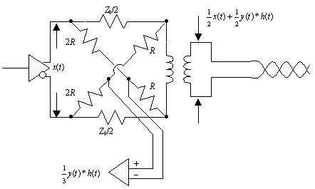
The main factors that limit the performance of this circuit are parasitic capacitances within the transformer, imbalance in the resistor ratios, and the unavoidable uncertainty in the impedance of the cabling. A better hybrid circuit is formed by replacing the fixed fractional subtraction of  with a variable gain or a digital adaptive filter. A sufficiently complex adaptive digital filter can compensate for cable roughness and also cable-transition reflections simultaneously. Such a filter is called an adaptive echo cancellation circuit.
Digital adaptive hybrid cancellation (also called echo cancellation) is beyond the scope of this book; however, a general overview of the echo cancellation problem appears in [67] . An excellent introduction to the theory behind digital adaptive echo cancellation appears in [68] . A detailed study of the mathematics behind adaptive filters in general and adaptive echo cancellation in particular is given in [66] .
POINTS TO REMEMBER
- A hybrid circuit makes possible bidirectional full-duplex transmission through a single channel.
- A sufficiently complex adaptive digital filter can compensate for cable roughness and also cable-transition reflections simultaneously. Such a filter is called an adaptive echo cancellation circuit.
8.3.4 UTP: Near-End Crosstalk
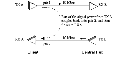
Any data link that transmits on one pair while listening on a different pair is susceptible to near-end crosstalk (NEXT). Figure 8.20 illustrates the 10BASE-T Ethernet system, showing the general behavior of NEXT. The distinction between NEXT and alien crosstalk (see next section) has to do with the source of the interference. NEXT, since it comes from your own transmitter, is somewhat under your control. Alien crosstalk, which may come from another application operating on different pairs within the same cable jacket, is not.
Figure 8.20. 10BASE-T installation showing behavior of NEXT.
The NEXT effect for UTP differs markedly from the simple NEXT effect observed on two parallel printed circuit board tracks X and Y . In the pcb case a fast step edge on trace X induces ( ideally ) a simple boxcar-shaped pulse of NEXT voltage on trace Y .
The UTP crosstalk waveform is complicated by the twisting pattern of the conductors. Every time one pair does a half twist, the adjacent NEXT reverses polarity. Successive twists tend, to first order, to cancel each other out. The crosstalk that is left over represents the degree to which the twisting was imperfect. The twisting imperfections comprise a classic second-order effect: a random generator of NEXT.
NEXT may be modeled as a large number of separate little crosstalk effects, each with a frequency response proportional to w . The mathematical model used to generate synthetic NEXT transfer functions is identical with the one used to produce SRL transfer functions, so the NEXT effect has an overall frequency response proportional to the 3/4 power of frequency (Figure 8.21). NEXT must be included in the SNR budget for any full-duplex system.
Figure 8.21. Synthetic NEXT curves for category 3 UTP generated by a random SRL/NEXT model.
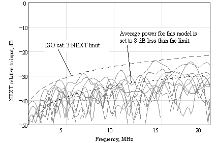
If you are using 100- W UTP cable, TIA/EIA 568-B cable specifications limit the NEXT to the maximum values presented in Table 8.5. The table lists NEXT specifications using formulas exactly as shown in the relevant standards. For purposes of comparison, the table also shows the NEXT performance at the specific frequency of 5 MHz. Since all the curves vary with 15log( f ), you can extrapolate the entire high-frequency performance curve of each cable from that single value.
Table 8.5. NEXT for UTP and 150- W STP-A Cabling (Worst Pair)
|
Cable |
Freq. Range(MHz) |
Min. allowed NEXT loss [1] , [2] (dB) |
Min. allowed NEXT loss at 10 MHz (dB) |
|---|---|---|---|
|
cat-3 |
0.772 “16 |
11.26 “15log 10 ( f /100) [3] |
26.3 |
|
cat-5e |
0.772 “100 |
35.3 “15log 10 ( f /100) [4] |
50.3 |
|
cat-6 |
0.772 “250 |
44.3 “15log 10 ( f /100) |
59.3 |
|
150- W STP-A |
1 “300 |
38.5 “15log 10 ( f /100) |
53.5 |
[1] NOTE (1) “Values from TIA/EIA-568-B.2-2001, as measured for cables greater than 100m in length.
[2] NOTE (2) “In all formulas, the frequency variable f is in MHz.
[3] NOTE (3) ”The form of this equation has been modified to conform with the other NEXT equations in this table.
[4] NOTE (4) ”This value is 3 dB more stringent than the older EIA/TIA 568-A category 5.
As shown in the table, 150- W STP-A has the best NEXT performance. That's part of what makes it easy to get a high-speed data link to work on 150- W STP-A. In comparison to category 5 UTP, the good NEXT performance of 150- W STP-A is obtained, in large measure, by increased physical separation and shielding of the conductors, both of which tend to increase the bulk and weight of the cable.
Whatever cable you use, an overall NEXT calculation, including NEXT from all adjacent pairs, must be included in the SNR budget for any bidirectional full-duplex system.
It is traditional when making multi-disturber NEXT calculations to assume that all pairs do not simultaneously suffer from worst-case NEXT. This argument implies that the worst-case sum of NEXT noise from N adjacent disturbers should be less than N times the disturbance from the worst pair. Such procedures have been in use (at least) since the inception of the 10BASE-T standard (see annex A of the IEEE 802.3 standard "Example Crosstalk Computation for Multiple Disturbers"). Take caution when using this procedure: Its proper use depends heavily on a precise knowledge of the statistics of NEXT in multiple-pair cables, something which is extremely difficult to pin down with any accuracy and which is not guaranteed by any known standard, specification, or measurement procedure.
One of the worst cases for NEXT happens when the far end of a short cable is left unplugged. With the far-end termination missing, the amplitude of the transmitted signal in most double-end-terminated architectures will double. For similar reasons, the receiver becomes twice as susceptible to noise. The overall effect is a quadrupling of crosstalk into the receiver. You may be thinking it doesn't matter how much crosstalk you have when the system is dysfunctional , but there is a subtle catch: If the crosstalk is sufficient to trip the carrier-detect threshold on the receiver, it will think it is listening to a system at the far end, when all it is doing is hearing its own crosstalk. This can cause some very strange system behavior. It is always a good idea to implement a hardware signal-detect function that disqualifies any strange -looking incoming signals. The signal-detect function should always reliably detect disconnected or powered -off conditions at the other end of the cable.
A circuit that fixes the NEXT problem is called an adaptive near-end crosstalk canceller. It takes as inputs the collection of all transmitted signals and produces one output for each received signal. The outputs attempt to predict the precise interference that will occur on each received signal line, given the past history of the transmitters. The circuit then subtracts the predicted interference from each incoming line. What remains is the desired signal from the other end. The design of good NEXT cancellation algorithms is a challenging digital signal processing problem (see [66] , [67] ).
POINTS TO REMEMBER
- NEXT is modeled as a summation of many noise sources with random amplitudes.
- NEXT grows at a rate of 15 dB per decade.
8.3.5 UTP: Alien crosstalk
Alien crosstalk is noise that comes from other devices that use conductors within the same cable jacket as your system. Within the context of a 10BASE-T installation, an alien device could be a second 10BASE-T device or perhaps a telephone.
The 10BASE-T standards committee went through an exhaustive process of evaluating alien crosstalk for category 3 UTP. The committee determined that one primary source of alien noise would be telephone devices operating on an adjacent pair. The worst-case noise generated by this device happens when the telephone handset is raised while the phone is ringing, interrupting the ringing current. The differential noise spike coupled onto an adjacent pair by a ringing-interruption event can be as large as 264 mV, as measured using a 100-ohm receiver having a bandwidth B of approximately 15 MHz. The noise measured varies in proportion to the receiver bandwidth B .
While there was (and still is) some controversy about the rigor of the experimental procedure used to determine the 264-mV noise number, there is no question that Ethernet 10BASE-T systems that are designed to withstand 264 mV of differential noise prove extremely reliable in the field. [73] Other standards (notably 100BASE-TX) have addressed this issue by stipulating that any other unused pairs within the same jacket remain unused.
[73] By 1999 there were over 100 million Ethernet 10BASE-T nodes in operation worldwide.
The importance of the distinction between alien crosstalk and NEXT is that NEXT can be cancelled by a suitably sophisticated circuit similar to a digital adaptive hybrid. Alien crosstalk, because your circuit does not have access to the driving function x ( t ) within the alien device, cannot be cancelled.
The Gigabit Ethernet standard 1000BASE-T incorporates an elaborate form of multi-way crosstalk cancellation. This is a four-channel full-duplex system operating at 125 Mbaud per pair. It uses a PAM-5 coding to achieve a transmission rate of 250 Mb/s on each pair. Each receiver is programmed to cancel the echo from its own transmitter in addition to NEXT from the other three active transmitters. Because this system uses all four pairs, installers are not tempted to install alien devices within the same jacket.
POINT TO REMEMBER
- Alien crosstalk comes from devices occupying unused pairs within your cable jacket.
8.3.6 UTP: Far-End Crosstalk
Figure 8.22 illustrates the far-end crosstalk (FEXT) scenario present in 100BASE-T2. The 100BASE-T2 data link uses two pairs, each transmitting 50 Mb/s in a bidirectional, full-duplex mode over 100 meters of category 3 UTP. FEXT couples part of the signal from transmitter A over to receiver D (and B to C , etc.). FEXT affects any link that utilizes multiple pairs transmitting in the same direction within the same cable jacket.
Figure 8.22. 100BASE-T2 transmitter A induces FEXT measurable at receiver D .
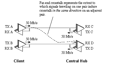
The FEXT parameters quoted in Table 8.6 are defined as equal-level far-end crosstalk (ELFEXT) measurements. ELFEXT is defined as the difference in dB between the signal levels measured at the inputs to transceivers C and D in Figure 8.22 when transmitting only from location A . The table includes information for categories 5e and 6 cabling.
ELFEXT for category 3 cables remains unspecified. This lack of specification hampered the development of standards for 100BASE-T2 and 100BASE-T4 transceivers, two variants of Ethernet built to operate at 100 Mb/s over category 3 cable. Both of these variants depended on the use of wire pairs transmitting in the same direction within the same jacket.
In the absence of concrete specifications for ELFEXT, the 100BASE-T2 and 100BASE-T4 LAN standards assumed , based on laboratory measurements, that ELFEXT on category 3 cables would never exceed 5.0-20log(f/100) dB over the range of 2 MHz to 16 MHz. That assumption was used in both cases as part of the signal-to-noise budget. Unfortunately, the cable industry never adopted the assumption as a formal specification, nor were the sales of either transceiver sufficient to prove the assumption correct before both variants were overtaken in the marketplace by the category-5 version, 100BASE-TX.
Table 8.6. ELFEXT Limits
|
Standard |
Cable |
Freq. Range(MHz) |
Min. allowed ELFEXT loss(dB) |
|---|---|---|---|
|
EIA/TIA 568-B |
cat-5e |
1 “100 |
23.8 “20log 10 ( f /100). |
|
EIA/TIA 568-B |
cat-6 |
1 “250 |
27.8 “20log 10 ( f /100). |
|
NOTE (1) ”Values listed apply to cable only. A complete link budget will differ (see EIA-568-B). |
|||
|
NOTE (2) ”150- W STP-A incorporates only two pairs, one used in either direction, rendering the ELFEXT inapplicable. |
|||
|
NOTE (3) ”Values of ELFEXT for category 3 cabling have never been standardized. |
|||
FEXT may be modeled as a large number of separate crosstalk effects in a manner similar to equation [8.6], but with major simplifications . Wherever on the cable the crosstalk occurs, the signal eventually must traverse one complete cable length. [74] Therefore, the term H ( w ,2 n · D x ) in [8.6] is replaced by H ( w , L ), where L is the total length of the cable. Factoring out the product j w H ( w , L ) from under the sum in [8.6] leaves you with nothing but a pure differentiation, multiplied by the unidirectional cable response, further multiplied by a single consolidated random variable (the summation of a 's), which you may adjust to produce the appropriate worst-case behavior. ELFEXT noise grows in direct proportion to frequency and generally with the square root of the cable length.
[74] The crosstalk signal generated by segment n travels along the aggressor pair from position 0 to position n l , where the crosstalk happens, and thence along the victim pair from that point to the end of the cable.
FEXT must be included in the SNR budget for systems that transmits on multiple pairs in the same direction.
Whenever you encounter a situation where FEXT is important, you may also wish to consider the effect of timing skew between the pairs. Timing skew is the worst-case (maximum) difference between the propagation delay of any of the pairs in a multipair data link. Timing skew affects any data link that starts with a single transmitted data stream, parcels it out among more than one parallel path, and then reassembles the fragments at the far end. The fragments arriving at the receiver must be de-skewed before they are reassembled into a complete data stream. The de-skew logic realigns the arriving fragments by building out the delay of the quickest pairs to match the delay of the slowest pairs.
In UTP data links, the timing skew slowly varies over the period of a day with the changes in temperature of the cable. It is not sufficient to measure the skew once when the link is first powered on and then forever compensate with a fixed de-skew circuit. Data arriving at the receiver must be continuously de-skewed before assembling it into a complete data stream.
Your choice of fragment size has a dramatic impact on the complexity of the de-skew circuitry. If you select a fragment size whose duration is smaller than the timing skew (for example, a single bit), you will have to contend with the possibility that fragments from one data pair may be delayed by more than one full fragment, as compared to fragments from another pair. Therefore, the de-skew circuitry must incorporate means to detect and track which fragment follows which.
If, on the other hand, you select a fragment size whose duration is larger than the timing skew (for example, a 32-bit word), the order of reassembly for fragments is never in question. The de-skew circuitry merely realigns the fragments to begin on exact timing boundaries, using minor timing adjustments smaller than the fragment size. Larger fragments have the advantage of simplifying the de-skew circuitry, but the disadvantage of increasing overall latency.
POINTS TO REMEMBER
- FEXT is modeled as a single noise source with a random amplitude.
- FEXT grows at a rate of 20 dB per decade.
8.3.7 Power sum NEXT and ELFEXT
TIA/EIA 568-B specifies for four-pair horizontal wiring, categories 5e and 6, the worst-case aggregate power coupled into any victim pair as being no more than 3 dB worse than the noise power coupled from the most aggressive of the other three pairs within the same jacket. [75]
[75] In the case of category 6 NEXT the power-sum limit exceeds the pair-to-pair limit by only 2 dB.
This number compares with the 10log(3)=4.77 dB increase in total coupled power you would expect from three uncorrelated sources of equal strength. In effect, this specification says that while there may be one combination of pairs that press up against the limit for pair-to-pair NEXT or ELFEXT, not all combinations of pairs may do so.
POINT TO REMEMBER
- Within a single jacket there may be one combination of pairs that press up against the limit for pair-to-pair NEXT or ELFEXT, but not all combinations of pairs may do so.
8.3.8 UTP: Radio-Frequency Interference
Radio waves impinging on a twisted-pair cable from faraway sources influence both conductors equally, generating common-mode currents within the cabling. In some cases the common-mode currents can be quite large. Any imbalance in the connectors, transceivers, or cables will convert part of the common-mode induced power into a differential mode, which is picked up by differential receivers.
In a UTP system, the best antidote for RFI is good signal balance. To the extent that you can make the system perfectly symmetrical, the conversion from common to differential mode won't happen. Good transceivers that deliver excellent common-mode balance usually couple to the line through a transformer or common-mode choke (or both). Such transceivers are largely immune to external RFI as well as 60-Hz power shifts. Keep in mind that any system with a transformer will require the use of a DC-balanced code [76] or a DC-resoration circuit in the receiver.
[76] A DC-balanced data code is designed to equalize the numbers of ones and zeroes in the data stream, making it possible to transmit the code successfully through transformers and other AC-coupled circuits. An example of a DC-balanced data code is the well-known Manchester code.
Several authors have attempted to quantify the expected levels of RF noise on UTP cabling. The best presentation I've seen on this subject was delivered by W. Michael King of Costa Mesa, California, in a speech to the IEEE 802.3 Ethernet committee in September 1993. In that presentation, Mr. King emphasized the point that RF pickup is a four-stage process. To predict actual levels of interference in an indoor LAN-type application, you need to know
- The intensity of RF fields in the outside environment,
- The degree of RF shielding provided by a building,
- The degree to which RF fields couple differentially into category 3 UTP, and
- The effect of input filtering present in the LAN receiver.
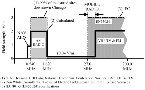
The intensity of RF fields in the outdoor environment (U.S. only) may be estimated based on the relevant power, frequency, and antenna height restrictions imposed on the AM, FM, and TV broadcast industry by the Federal Communications Commission. This data has been compiled by, among others, Don White Consultants and is summarized in Figure 8.23. Also shown in that figure are actual measurements of RF field intensity in the AM broadcast band taken by AT&T in the city of Chicago (deemed representative of a major U.S. metropolitan area). Potential emissions from mobile radios, which in contrast to major broadcast services can be moved quite close to the affected wiring, are depicted as well. The limits drawn for mobile radio emissions are those imposed by EN55024 specifications. The general conclusion from Figure 8.23 is that there are two major bands of interference, the AM band from .540 to 1.620 MHz and the Mobile/TV/FM from 27 to 200 MHZ and beyond. In each band the worst-case outdoor field strength expected at an ordinary commercial building site is 3 V/m. There are no licensed high-powered radio sources in the United States occupying the midrange from 1.620 to 27.0 MHz.
Figure 8.23. Interoffice products must tolerate 3 V/m RF fields in the AM and Mobile/TV/FM bands.
Bob Smith [77] (of Synoptics, later known as Bay Networks) in 1992 and 1993 measured FM and AM radio station pickup on category 3 cables. His measurements are reproduced in Figure 8.24. These measurements were performed using a single segment of well-terminated category 3 cable, 100-m in length, held in the horizontal polarization, and measuring the differential pickup. Mr. Smith's measurements were made using actual AM and FM broadcast signals located near San Jose, California. For each station, he carefully measured the local field strength using a calibrated loop antenna and then normalized his measured differential pickup to predict what would have resulted from the presence of a 3 V/m local electric field. The measurements were made outdoors and so do not benefit from the building-attenuation effect anticipated in real-life LAN applications. In the absence of building attenuation you may conclude from this figure that RF pickup for horizontally polarized cables is less than 40 mV in the AM band and less than 200 mV in the Mobile/FM/TV band.
[77] The same Bob Smith who patented the common-mode termination used on some FDDI-Copper and 100BASE-TX transceivers.
Mr. Smith's measurements represented cable pickup in a long, horizontal cable run. What about vertical cable runs, as often happen in tall buildings ?
In the AM band most buildings efficiently attenuate the RF field intensity. Try it. With a portable AM radio, find out how many stations you can pick up outside your building, and then move the receiver indoors. The indoor reception is usually much worse. In a tall steel building the attenuation of AM radio stations ranges anywhere from 30 to 50 dB. This attenuation is so impressive that AM radios almost never work in high-rise buildings. RF pickup of AM radio stations on category 3 cable in high-rise buildings is therefore not much of a problem. Wooden or brick buildings don't provide as much attenuation as a steel high-rise, but neither are they as tall, so the horizontally-measured results in Figure 8.24 should apply.
Figure 8.24. The susceptibility of typical category 3 UTP to an external 3 V/m RF field has been measured in the AM radio band (Bob Smith, Sept. 1993) and also in the Mobile, TV & FM band (Bob Smith, Oct. 1992).
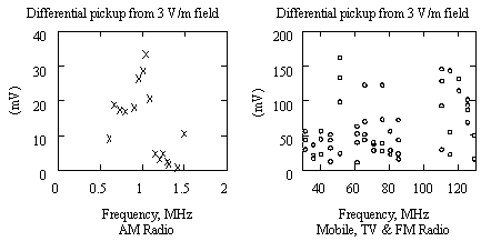
In the FM radio band building attenuation is almost nonexistent, especially near the edges of the building. FM radio stations come through practically full-strength. Even worse, some mobile services may be literally located inside the building, where any putative building attenuation couldn't possibly help. You can't count on building attenuation to help you in the Mobile/FM/TV band. For category 3 cable systems, you must either design your system to work with 200 mV of RF noise or provide a low-pass filter in the receiver to filter out potential Mobile/FM/TV interference.
In a typical installation, only one RF source will produce the lion's share of the interference, so you don't have to worry about summing noise across multiple interference sources. The worst-case noise limits should be set at 40 mV in the AM band and 200 mV in the Mobile/FM/TV band.
If you limit the spectral content of your signals to the band below 27 MHz and provide good low-pass filtering in the receiver to cut off all interference above 27 MHz, you can eliminate most of the Mobile/FM/TV interference. That should result in a category 3 data link that picks up less than 40 mV of noise in most commercial situations.
Exceptions to this rule could include
- Installations immediately adjacent to high-powered commercial broadcast antennas,
- Installations immediately adjacent to high-powered military broadcast services, and
- Installations immediately adjacent to low-powered local transmitters if they are located within a few feet of the cabling.
Category 5e cabling, which sports a tighter twist and better overall balance of each pair, can be expected to pick up approximately 12 dB less RF interference than category 3 cabling at all frequencies. For category 6 cabling, the expected difference is approximately 17 dB.
POINTS TO REMEMBER
- The best antidote for RFI is good signal balance.
- A 27-MHz low-pass filter applied to category-3 horizontal cabling should cut RFI to less than 40 mV in most commercial situations.
- Categories 5e and 6 cabling pick up less RFI.
8.3.9 UTP: Radiation
UTP common-mode signals radiate much more effectively than differential mode signals. The key to obtaining good radiated performance is good common-mode balance. This problem is equivalent to the problem of hardening your system against RFI, and the same solutions apply.
Examples of systems that can be made to pass FCC Class-A radiated emissions, given a sufficiently well-balanced coupling network, appear in Table 8.7. For each link type, the table lists the number of simultaneously active pairs, the overall data transfer rate, the baud rate on each pair, and the maximum differential dV/dt on each pair. If you are planning a system with either a faster or larger signal swings than these known-good designs, now would be a good time to review your product plans.
The 100BASE-TX and 1000BASE-T systems are both scrambled , meaning that the outgoing data at the transmitter has been multiplied (X-OR'd) with a known, repetitive pseudorandom sequence. The inverse operation is then applied in the receiver to recover the original data. Scrambling accomplishes several purposes:
- Scrambling spreads the spectral power density of the transmitted signal over a wide range of frequencies. This reduces the peak radiation in any one band.
- Scrambling reduces unintentional correlation between successive bits in the outgoing data stream. This helps the adaptive equalizer circuits to converge quickly and efficiently.
- Scrambling reduces unintentional correlation between the outgoing and received data streams. This makes the near-end noise cancellation systems work better.
Scrambling in the 100BASE-TX is applied after 4B5B data coding, with the unfortunate result that several properties of the 4B5B data code, like DC-balance and limited run-length, are destroyed . The 1000BASE-T standard takes the more reasonable approach of scrambling the data prior to coding.
Table 8.7. Systems That Pass FCC Class-A Radiated Emissions Limits
|
System |
Cable |
Active pairs within cable |
Data rate Mb/s |
Baud rate per pair |
Max.diff. dV/dt |
|---|---|---|---|---|---|
|
IEEE 802.310BASE-T |
Cat. 3 |
2 |
10 |
20 Mbaud(10 MHz Manchester) |
0.16 V/ns |
|
IEEE 802.3100BASE-TX |
Cat. 5 |
2 |
100 |
125 Mbaud(3-level MLT-3) scrambled |
0.33 V/ns |
|
IEEE 802.31000BASE-T |
Cat. 5 |
4 |
1000 |
125 Mbaud(5-level PAM with pre-distortion) scrambled |
0.33 V/ns |
POINTS TO REMEMBER
- The key to obtaining good radiated performance is good common-mode balance.
- Scrambling spreads the spectral power density of the transmitted signal, reducing the peak radiation.
Fundamentals
- Impedance of Linear, Time-Invariant, Lumped-Element Circuits
- Power Ratios
- Rules of Scaling
- The Concept of Resonance
- Extra for Experts: Maximal Linear System Response to a Digital Input
Transmission Line Parameters
- Transmission Line Parameters
- Telegraphers Equations
- Derivation of Telegraphers Equations
- Ideal Transmission Line
- DC Resistance
- DC Conductance
- Skin Effect
- Skin-Effect Inductance
- Modeling Internal Impedance
- Concentric-Ring Skin-Effect Model
- Proximity Effect
- Surface Roughness
- Dielectric Effects
- Impedance in Series with the Return Path
- Slow-Wave Mode On-Chip
Performance Regions
- Performance Regions
- Signal Propagation Model
- Hierarchy of Regions
- Necessary Mathematics: Input Impedance and Transfer Function
- Lumped-Element Region
- RC Region
- LC Region (Constant-Loss Region)
- Skin-Effect Region
- Dielectric Loss Region
- Waveguide Dispersion Region
- Summary of Breakpoints Between Regions
- Equivalence Principle for Transmission Media
- Scaling Copper Transmission Media
- Scaling Multimode Fiber-Optic Cables
- Linear Equalization: Long Backplane Trace Example
- Adaptive Equalization: Accelerant Networks Transceiver
Frequency-Domain Modeling
- Frequency-Domain Modeling
- Going Nonlinear
- Approximations to the Fourier Transform
- Discrete Time Mapping
- Other Limitations of the FFT
- Normalizing the Output of an FFT Routine
- Useful Fourier Transform-Pairs
- Effect of Inadequate Sampling Rate
- Implementation of Frequency-Domain Simulation
- Embellishments
- Checking the Output of Your FFT Routine
Pcb (printed-circuit board) Traces
- Pcb (printed-circuit board) Traces
- Pcb Signal Propagation
- Limits to Attainable Distance
- Pcb Noise and Interference
- Pcb Connectors
- Modeling Vias
- The Future of On-Chip Interconnections
Differential Signaling
- Differential Signaling
- Single-Ended Circuits
- Two-Wire Circuits
- Differential Signaling
- Differential and Common-Mode Voltages and Currents
- Differential and Common-Mode Velocity
- Common-Mode Balance
- Common-Mode Range
- Differential to Common-Mode Conversion
- Differential Impedance
- Pcb Configurations
- Pcb Applications
- Intercabinet Applications
- LVDS Signaling
Generic Building-Cabling Standards
- Generic Building-Cabling Standards
- Generic Cabling Architecture
- SNR Budgeting
- Glossary of Cabling Terms
- Preferred Cable Combinations
- FAQ: Building-Cabling Practices
- Crossover Wiring
- Plenum-Rated Cables
- Laying Cables in an Uncooled Attic Space
- FAQ: Older Cable Types
100-Ohm Balanced Twisted-Pair Cabling
- 100-Ohm Balanced Twisted-Pair Cabling
- UTP Signal Propagation
- UTP Transmission Example: 10BASE-T
- UTP Noise and Interference
- UTP Connectors
- Issues with Screening
- Category-3 UTP at Elevated Temperature
150-Ohm STP-A Cabling
- 150-Ohm STP-A Cabling
- 150- W STP-A Signal Propagation
- 150- W STP-A Noise and Interference
- 150- W STP-A: Skew
- 150- W STP-A: Radiation and Safety
- 150- W STP-A: Comparison with UTP
- 150- W STP-A Connectors
Coaxial Cabling
- Coaxial Cabling
- Coaxial Signal Propagation
- Coaxial Cable Noise and Interference
- Coaxial Cable Connectors
Fiber-Optic Cabling
- Fiber-Optic Cabling
- Making Glass Fiber
- Finished Core Specifications
- Cabling the Fiber
- Wavelengths of Operation
- Multimode Glass Fiber-Optic Cabling
- Single-Mode Fiber-Optic Cabling
Clock Distribution
- Clock Distribution
- Extra Fries, Please
- Arithmetic of Clock Skew
- Clock Repeaters
- Stripline vs. Microstrip Delay
- Importance of Terminating Clock Lines
- Effect of Clock Receiver Thresholds
- Effect of Split Termination
- Intentional Delay Adjustments
- Driving Multiple Loads with Source Termination
- Daisy-Chain Clock Distribution
- The Jitters
- Power Supply Filtering for Clock Sources, Repeaters, and PLL Circuits
- Intentional Clock Modulation
- Reduced-Voltage Signaling
- Controlling Crosstalk on Clock Lines
- Reducing Emissions
Time-Domain Simulation Tools and Methods
- Ringing in a New Era
- Signal Integrity Simulation Process
- The Underlying Simulation Engine
- IBIS (I/O Buffer Information Specification)
- IBIS: History and Future Direction
- IBIS: Issues with Interpolation
- IBIS: Issues with SSO Noise
- Nature of EMC Work
- Power and Ground Resonance
Points to Remember
Appendix A. Building a Signal Integrity Department
Appendix B. Calculation of Loss Slope
Appendix C. Two-Port Analysis
- Appendix C. Two-Port Analysis
- Simple Cases Involving Transmission Lines
- Fully Configured Transmission Line
- Complicated Configurations
Appendix D. Accuracy of Pi Model
Appendix E. erf( )
Notes
EAN: N/A
Pages: 163
 f
f 