Skin Effect
High-frequency current in a practical conductor does not flow uniformly throughout the cross-sectional area of the conductor. Magnetic fields within the conductor adjust the distribution of current, forcing it to flow only in a shallow band just underneath the surface of the conductor. The redistribution of current increases the apparent resistance of the conductor. In transmission lines we call this increase in resistance the skin effect . The thickness of the conduction band d is called the skin depth of the conductor.
The skin effect is an inductive mechanism related to the rate of change of magnetic fields within the conductor, so it becomes increasingly intense at higher frequencies. Below a certain cutoff frequency w d the skin effect is still present, but not at a noticeable level. Above w d , the skin effect squeezes the current into progressively more shallow regions at the periphery of the conductor, increasing the apparent AC resistance of the conductor without limit in proportion to the square root of frequency.
The skin effect governs the behavior of all conductors. As an example, Figure 2.10 depicts the series resistance of RG-58/U coaxial cable plotted as a function of frequency. The plot uses log-log axes. Figure 2.10 also shows, on the same axes, the series inductive reactance 2 p fL of the cable, assuming L = 253 nH/m.
Figure 2.10. Above the onset of the skin effect the series resistance of the center conductor markedly increases.
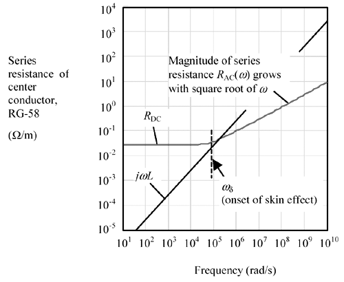
At frequencies below the skin-effect cutoff frequency w d the series resistance maintains a constant value equal to the total DC resistance of the conductors (both the inner signal conductor and shield are added in series). Beyond w d the effective series resistance rises with the square root of frequency.
2.6.1 What Causes the Skin Effect, and What Does It Have to Do With Skin?
To understand the skin effect, you must first understand how eddy currents operate within a solid conductor. Figure 2.11 depicts a sheet of conducting material, illuminated from the left side with a changing magnetic field. In a good conductor the presence of such a changing magnetic field sets up circulating eddy currents within the material, shown as dotted lines. The eddy currents circulate around the incoming lines of magnetic force, whose lines of flux point to the right. Although I've drawn the eddy currents as individual loops, in reality the loops merge continuously together across the sheet, forming an overall counterclockwise circulation of current around the perimeter of the sheet.
Figure 2.11. A changing magnetic flux creates eddy currents in a conducting plane.
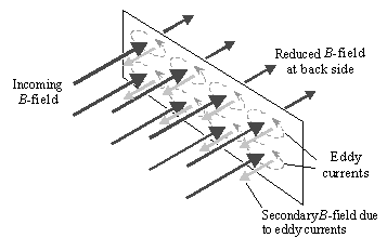
The eddy currents generate their own magnetic fields. The lines of magnetic flux associated with these secondary fields point to the left, always bucking the direction of the incoming field. [15] When the resistivity of the material is high, or the material is thin, the eddy currents remain small and the intensity of the secondary field comprises no more than a small perturbation to the incoming field.
[15] To do otherwise would lead to the possibility of perpetual motion.
If the resistivity is lowered , or the sheet thickened, the eddy currents increase and the secondary magnetic fields grow to a more noticeable magnitude. [16] An observer located behind the sheet begins to see partial cancellation of the incoming and secondary fields. In other words, a good conducting sheet acts as a magnetic shield that attenuates the passage of magnetic flux.
[16] But never larger than the amplitude of the incoming field.
Note that the above discussion relates only to magnetic fields perpendicular to the sheet. Magnetic lines of force running parallel to the sheet do not penetrate it and so do not create eddy currents.
In summary, magnetic lines of force intercepting a conducting object cause eddy currents, and the eddy currents reduce the intensity of the perpendicular magnetic field at the surface of the conductor. The eddy currents reduce the intensity of magnetic fields observed on the other (back) side of the sheet as well. The ratio of the field amplitude at the back of the sheet to the incoming field amplitude on the front is called the shielding effectiveness of the sheet.
If you add a second sheet in parallel with the first, the second sheet attenuates the field amplitude a second time. If you cascade a set of n parallel sheets, the overall structure should exponentially improve the shielding by n times. If you simply use a sheet n -times thicker, you get a similar result ”the field on the back side decays exponentially with the thickness of the sheet.
I have left many details out of this general discussion in order to communicate one, simple main result: The magnetic fields within a conductor decay exponentially as you move from the surface of any conductor towards the interior . The whole story is considerably more complicated, as it involves consideration of both the electric and magnetic fields, the wave impedance of the impinging wave, the characteristic impedance of the conducting medium, and reflections back and forth across the thickness of the sheet. A good, practical summary of the issues appears in [3] . Detailed, mathematically complete descriptions may be found in [4] and [5] .
The thickness of material required to reduce the internal magnetic field intensity within the conductor by a factor of 1/ e is called the skin depth of the material. For a good conductor the skin depth d depends on the frequency of operation, the conductivity, and the magnetic permeability of the material. In practice you will find that materials many skin depths thick make excellent magnetic shields , while materials less thick than one skin depth provide only partial attenuation of magnetic fields.
Equation 2.42

|
where |
d is the skin depth over which magnetic fields are attenuated by a factor of 1/ e (m), |
|
|
w = 2 p f is the frequency of operation (rad/s), |
||
|
m is the magnetic permeability of the conducting material (H/m), and |
||
|
s is the conductivity of the conducting material (S/m). |
||
|
For annealed copper at room temperature s = 5.80 ·10 7 S/m. |
||
|
For nonmagnetic materials m = 4 p ·10 “7 H/m. |
||
Equation [2.42] prescribes changes in the skin depth in inverse proportion to the square root of frequency. Table 2.2 lists the skin depths of several materials at various frequencies.
As you can see from the table, the thickness of a 1/2-oz copper layer (0.017 mm) spans many skin depths at frequencies above 100 MHz (the primary region of interest to high-speed digital designers). You may conclude that pcb traces and planes appear many skin depths thick at high frequencies and that these objects act, at high frequencies, as excellent magnetic shields.
2.6.2 Eddy Currents within a Conductor
Figure 2.12 shows a cutaway view of the of eddy currents present within the body of a circular conductor. This figure assumes the frequency of operation w << w d , so the total current I = cos( w t ) remains distributed fairly evenly across the entire cross-sectional area of the conductor.
Figure 2.12. A changing magnetic field within the body of a conductor creates internal eddy currents that affect the distribution of current within the conductor.
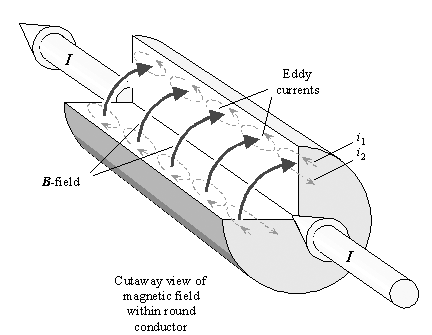
Table 2.2. Skin Depth of Conductive Media
|
Carbon steel SAE1045 |
Stainless steel [1] |
Nickel |
Copper, annealed |
Aluminum |
Soil (Earth) [2] |
|
|---|---|---|---|---|---|---|
|
Relative magnetic permeability |
1000 |
500 |
100 |
1 |
1 |
1 |
|
Conductivity (S/m) |
5.80 ·10 6 |
1.16 ·10 6 |
1.16 ·10 7 |
5.80 ·10 7 |
3.55 ·10 7 |
0.1 |
|
Frequency (Hz) |
Skin depth (mm) |
|||||
|
60 |
0.85 |
2.7 |
1.9 |
8.5 |
11. |
205. |
|
10 3 |
0.21 |
0.66 |
0.47 |
2.1 |
2.7 |
50. |
|
10 4 |
0.066 |
0.21 |
0.15 |
0.66 |
0.85 |
16. |
|
10 5 |
0.021 |
0.066 |
0.047 |
0.21 |
0.27 |
5.0 |
|
10 6 |
0.0066 |
0.021 |
0.015 |
0.066 |
0.085 |
1.6 |
|
10 7 |
0.0021 |
0.0066 |
0.0047 |
0.021 |
0.027 |
0.52 |
|
10 8 |
0.00066 |
0.0021 |
0.0015 |
0.0066 |
0.0085 |
0.20 |
|
10 9 |
0.00021 |
0.00066 |
0.00047 |
0.0021 |
0.0027 |
0.16 |
|
10 10 |
0.000066 |
0.00021 |
0.00015 |
0.00066 |
0.00085 |
0.16 |
[1] NOTE (1) ”Values for steel alloys vary tremendously. Some stainless steels have almost no magnetic properties. See [3], p. 163, and [4], p. 244.
[2] NOTE (2) ”above 100 MHz the Earth is no longer a good conductor, so the formula for skin depth changes.
The changing current I induces a changing magnetic field ( curved arrows). These magnetic lines of force cut through the body of the conductor, creating circulating eddy currents internal to the conductor (dotted lines). As w slowly increases, the magnetic fields grow in proportion to w , and so do the eddy currents.
The end of the conductor is cut away in the drawing to show eddy current i 1 flowing near the periphery of the conductor in a direction aligned with the major direction of current flow and eddy current i 2 flowing interior to the conductor in the opposite direction. Even though these currents are depicted in the cutaway view in only two radial positions, they occur at all radial positions around the conductor. The eddy currents circulate end to end everywhere throughout the conductor. The eddy currents increase the effective current density around the periphery of the conductor while decreasing it in the middle.
If you raise w well above w d the eddy current effect becomes extremely pronounced, finally expunging all current (and all magnetic flux) from the center of the conductor. In the limit at very high frequencies the skin effect restricts the flow of current to a shallow band just under the surface of the conductor. The effective depth of the conduction band (skin depth) is given by [2.42]. If at frequency w the skin depth of the material is much less than half the conductor thickness, then current hardly penetrates at all to the interior of the conductor.
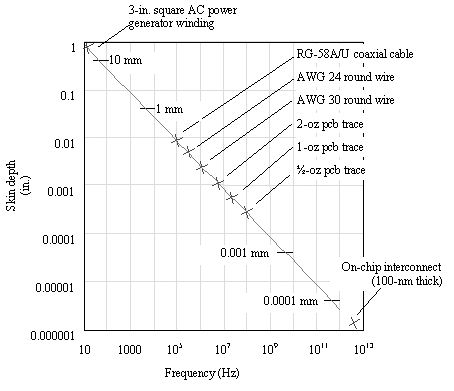
Figure 2.13 plots the skin depth for copper versus frequency, marking out the particular frequencies at which the skin depth takes hold for various types of conductors.
Figure 2.13. The X positions mark the skin-effect onset frequency for each conductor type.
2.6.3 High and Low-Frequency Approximations for Series Resistance
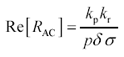
Once a conductor falls under the grip of the skin effect, current flows only in a shallow band of effective depth d around the periphery of the conductor. In mathematical language, the skin effect restricts the flow of current to an annular ring of thickness d and perimeter p , having cross-sectional area equal to p d . The effective resistance of a conductor in the skin-effect region is
Equation 2.43
|
where |
Re[ R AC ] is the real part of the skin-effect impedance ( W /m), assuming you are operating at a frequency high enough that wire radius greatly exceeds the skin depth (i.e., w >> w d ), |
|
p is the perimeter of a cross-section of the signal conductor (m), [17] |
|
|
d is the skin depth of the signal conductor at the frequency of operation (m), |
|
|
s is the conductivity of the signal conductor (S/m), |
|
|
k p is a correction factor determined by the proximity effect (see Section 2.10, "Proximity Effect"), and |
|
|
k r is a correction factor determined by the roughness effect (see Section 2.11, "Surface Roughness"). |
[17] For example, the perimeter of a round conductor with diameter d is p d . The perimeter of a rectangular conductor having width w and thickness t is 2( w + t ).
For round conductors well separated from the path of returning signal current, the factor k p equals unity. For conductors that are smooth on a scale comparable to the skin depth the factor k r also equals unity.
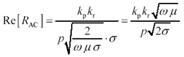
Substituting [2.42] for d yields an expression that shows how R AC changes with frequency. Since the conductor's apparent resistance is inversely proportional to the depth of current flow (the skin depth), and equation [2.43] says that the skin depth varies inversely proportional to the square root of frequency, you may conclude that the skin-effect resistance grows proportional to the square root of w .
Equation 2.44
|
where |
Re[ R AC ] is the real part of the skin-effect impedance ( W /m), assuming w >> w d , |
|
k p is a correction factor determined by the proximity effect (see Section 2.10, "Proximity Effect"), and |
|
|
k r is a correction factor determined by the roughness effect (see Section 2.11, "Surface Roughness"). |
|
|
p is the perimeter of a cross-section of the signal conductor (m), |
|
|
w is the frequency of operation (rad/s), |
|
|
m is the magnetic permeability of the signal conductor (H/m), and |
|
|
s is the conductivity of the signal conductor (S/m). |
|
|
For annealed copper at room temperature s = 5.800 ·10 7 S/m. |
|
|
For non-magnetic materials m = 4 p ·10 “07 H/m. |
|
Equation [2.44] is a high-frequency approximation for the series resistance of a wire. It applies to conductors of any reasonable convex cross-sectional shape, well separated from their return path, at w sufficiently far above w d that the skin depth remains far less than half the conductor thickness.
The low-frequency approximation for series resistance is [2.37]. It applies when w is sufficiently small that the conductor remains much thinner than the skin depth.
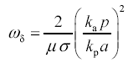
The crossover frequency w d is that frequency where the low-frequency and high-frequency models of series resistance coincide. Since in this frequency range the roughness factor is not usually significantly different from unity, it has been omitted from the equation.
Equation 2.45
|
where |
w d is the frequency (rad/s) where the skin-effect resistance predicted by [2.44] equals the DC resistance, |
|
k p is a correction factor determined by the proximity effect (see Section 2.10, "Proximity Effect"), and |
|
|
k a is the DC resistance correction factor (see Section 2.4, "DC Resistance"), |
|
|
m is the magnetic permeability of the signal conductor (H/m), |
|
|
s is the conductivity of the signal conductor (S/m), |
|
|
p is the perimeter of a cross-section of the signal conductor (m), and |
|
|
a is the cross-sectional area of the signal conductor (m 2 ). |
At the crossover frequency the actual resistance of a round wire appears 2.09 dB larger than either the DC or skin-effect models would predict.
Table 2.3 lists the crossover frequencies and the skin depth at which each crossover occurs for variously shaped conductors. The calculation of series resistance at mid-frequencies is a matter of some delicacy addressed in later sections.
Table 2.3. Skin-Effect Onset Frequency
|
Conductor geometry |
Skin-effect onset w d (rad/s) |
Skin depth d ( w d ) (m) |
|---|---|---|
|
Round, radius r |
|
|
|
Rectangular, w x t |
|
|
|
Square, w x w |
|
|
|
Thin, w x t, t << w |
|
|


POINTS TO REMEMBER
- Magnetic fields within a conductor adjust the distribution of high frequency current, forcing it to flow only in a shallow band just underneath the surface of the conductor.
- The effective depth of penetration of current is called the skin depth.
- The increase in the apparent resistance of the conductor caused by this redistribution of current is called the skin effect.
- At frequencies above the skin-effect onset frequency w d the effective series resistance of a conductor rises with the square root of frequency.
Fundamentals
- Impedance of Linear, Time-Invariant, Lumped-Element Circuits
- Power Ratios
- Rules of Scaling
- The Concept of Resonance
- Extra for Experts: Maximal Linear System Response to a Digital Input
Transmission Line Parameters
- Transmission Line Parameters
- Telegraphers Equations
- Derivation of Telegraphers Equations
- Ideal Transmission Line
- DC Resistance
- DC Conductance
- Skin Effect
- Skin-Effect Inductance
- Modeling Internal Impedance
- Concentric-Ring Skin-Effect Model
- Proximity Effect
- Surface Roughness
- Dielectric Effects
- Impedance in Series with the Return Path
- Slow-Wave Mode On-Chip
Performance Regions
- Performance Regions
- Signal Propagation Model
- Hierarchy of Regions
- Necessary Mathematics: Input Impedance and Transfer Function
- Lumped-Element Region
- RC Region
- LC Region (Constant-Loss Region)
- Skin-Effect Region
- Dielectric Loss Region
- Waveguide Dispersion Region
- Summary of Breakpoints Between Regions
- Equivalence Principle for Transmission Media
- Scaling Copper Transmission Media
- Scaling Multimode Fiber-Optic Cables
- Linear Equalization: Long Backplane Trace Example
- Adaptive Equalization: Accelerant Networks Transceiver
Frequency-Domain Modeling
- Frequency-Domain Modeling
- Going Nonlinear
- Approximations to the Fourier Transform
- Discrete Time Mapping
- Other Limitations of the FFT
- Normalizing the Output of an FFT Routine
- Useful Fourier Transform-Pairs
- Effect of Inadequate Sampling Rate
- Implementation of Frequency-Domain Simulation
- Embellishments
- Checking the Output of Your FFT Routine
Pcb (printed-circuit board) Traces
- Pcb (printed-circuit board) Traces
- Pcb Signal Propagation
- Limits to Attainable Distance
- Pcb Noise and Interference
- Pcb Connectors
- Modeling Vias
- The Future of On-Chip Interconnections
Differential Signaling
- Differential Signaling
- Single-Ended Circuits
- Two-Wire Circuits
- Differential Signaling
- Differential and Common-Mode Voltages and Currents
- Differential and Common-Mode Velocity
- Common-Mode Balance
- Common-Mode Range
- Differential to Common-Mode Conversion
- Differential Impedance
- Pcb Configurations
- Pcb Applications
- Intercabinet Applications
- LVDS Signaling
Generic Building-Cabling Standards
- Generic Building-Cabling Standards
- Generic Cabling Architecture
- SNR Budgeting
- Glossary of Cabling Terms
- Preferred Cable Combinations
- FAQ: Building-Cabling Practices
- Crossover Wiring
- Plenum-Rated Cables
- Laying Cables in an Uncooled Attic Space
- FAQ: Older Cable Types
100-Ohm Balanced Twisted-Pair Cabling
- 100-Ohm Balanced Twisted-Pair Cabling
- UTP Signal Propagation
- UTP Transmission Example: 10BASE-T
- UTP Noise and Interference
- UTP Connectors
- Issues with Screening
- Category-3 UTP at Elevated Temperature
150-Ohm STP-A Cabling
- 150-Ohm STP-A Cabling
- 150- W STP-A Signal Propagation
- 150- W STP-A Noise and Interference
- 150- W STP-A: Skew
- 150- W STP-A: Radiation and Safety
- 150- W STP-A: Comparison with UTP
- 150- W STP-A Connectors
Coaxial Cabling
- Coaxial Cabling
- Coaxial Signal Propagation
- Coaxial Cable Noise and Interference
- Coaxial Cable Connectors
Fiber-Optic Cabling
- Fiber-Optic Cabling
- Making Glass Fiber
- Finished Core Specifications
- Cabling the Fiber
- Wavelengths of Operation
- Multimode Glass Fiber-Optic Cabling
- Single-Mode Fiber-Optic Cabling
Clock Distribution
- Clock Distribution
- Extra Fries, Please
- Arithmetic of Clock Skew
- Clock Repeaters
- Stripline vs. Microstrip Delay
- Importance of Terminating Clock Lines
- Effect of Clock Receiver Thresholds
- Effect of Split Termination
- Intentional Delay Adjustments
- Driving Multiple Loads with Source Termination
- Daisy-Chain Clock Distribution
- The Jitters
- Power Supply Filtering for Clock Sources, Repeaters, and PLL Circuits
- Intentional Clock Modulation
- Reduced-Voltage Signaling
- Controlling Crosstalk on Clock Lines
- Reducing Emissions
Time-Domain Simulation Tools and Methods
- Ringing in a New Era
- Signal Integrity Simulation Process
- The Underlying Simulation Engine
- IBIS (I/O Buffer Information Specification)
- IBIS: History and Future Direction
- IBIS: Issues with Interpolation
- IBIS: Issues with SSO Noise
- Nature of EMC Work
- Power and Ground Resonance
Points to Remember
Appendix A. Building a Signal Integrity Department
Appendix B. Calculation of Loss Slope
Appendix C. Two-Port Analysis
- Appendix C. Two-Port Analysis
- Simple Cases Involving Transmission Lines
- Fully Configured Transmission Line
- Complicated Configurations
Appendix D. Accuracy of Pi Model
Appendix E. erf( )
Notes
EAN: N/A
Pages: 163
