The Concept of Resonance
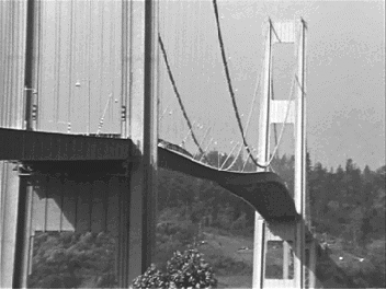
Atoms resonate. Oceans resonate. Your vocal chords resonate. The Tacoma Narrows bridge (Figure 1.2) used to resonate in high winds. Vibrating, periodic phenomena abound in nature, especially within high-speed digital electronics.
Figure 1.2. The Tacoma Narrows bridge in Washington State, known locally as "Galloping Gertie," heaving under the influence of heavy winds.

The technical requirements for resonance are simple. First, there must be two or more reservoirs for the storage of some amount of energy E along with a relatively loss-free mechanism for exchanging the energy between them. Such a system almost always harbors one or more modes of oscillatory behavior whereby the total stored system energy can slosh back and forth among the various storage modes.
Second, there must be a source of external power coupled into (at least) one of the reservoirs. The coupling mechanism must be capable of delivering power P into the system without unduly disturbing the resonant behavior.
Third, the external stimulation must excite the periodic resonant behavior you wish to excite. Otherwise, the system won't start resonating. In technical terms, this means that for linear systems the spectral power density of the source must overlap with the natural resonant frequency (or frequencies) of the system. For nonlinear phenomena, this spectral condition is usually helpful but not always required (see [2] ).
Resonant systems may be characterized by their quality factor, Q . The Q measures the reluctance of a system to give up its naturally stored energy. A system with high Q tends to resonate, or ring, for many cycles. A system with low Q damps quickly.
The value of Q is technically defined as the ratio of energy stored to the average energy dissipated per radian of oscillation. The range of Q values typically encountered in digital electronics ranges from less than unity (no resonance) to more than 10 6 (a highly resonant crystal oscillator).
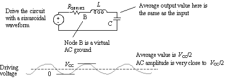
Let's do a specific example. Consider the simple RLC resonator depicted in Figure 1.3. It is representative of a short, unterminated pcb connection with a heavy capacitive load at the receiver. The resistor R SERIES represents the output impedance of the driving gate. In such a circuit, for a single resistance in series with the resonant elements, the Q equals
Equation 1.11

Figure 1.3. A short, unterminated pcb trace with a heavy capacitive load resembles this simple LC series-resonant circuit.

We'll assume in this example the Q is greater than one. Drive this circuit with a periodic waveform, and let the sine wave frequency match the natural frequency of oscillation. Assume the driver rise/fall times are just fast enough to perform this function, so the driving signal looks pretty sinusoidal. From these conditions we may derive the output amplitude of the voltage across the capacitive load. It may surprise you to find that the output amplitude can grow quite large.
To begin the analysis, break down the driving signal into two components : a steady-state DC offset and a sinusoid at frequency f . The amplitude of the DC offset is V CC /2 (that's the average value of the output). The amplitude of the fundamental frequency is also V CC /2. When added to the DC offset, this brings the peak excursions just up to V CC and down to zero. We will do the DC and AC analyses separately.
The DC analysis for this circuit is easy. Since input and output are connected with an inductor , the average value of the output must equal the average value of the input. Therefore, the DC component of the output waveform is precisely V CC /2.
The AC analysis for this circuit is not too hard either. It may be derived using an energy-balance equation. This equation will balance the energy delivered to the circuit during one radian of oscillation with the energy dissipated within the circuit over the same period.
Once the circuit has reached steady-state operation, the power delivered to the circuit per radian of oscillation is P /2 p f . The amount of energy dissipated per radian of oscillation (from the definition of Q ) is E/Q . These two quantities must balance:
Equation 1.12

|
where |
P is the power delivered to the circuit, |
|
E is the total energy stored within the circuit, and |
|
|
Q is the quality factor for the resonator, equal to |
You are driving the circuit at its resonant frequency, and you know that the input impedance of a perfect series LC resonator operated at its resonant frequency is zero. Therefore, the AC voltage at point (B) in the circuit must be zero. That implies that the full AC driving voltage of ± V CC /2 must appear across resistor R SERIES . The power P delivered to the circuit must therefore equal ½( V CC /2) 2 / R SERIES .
We also know that the total energy E sloshes back and forth between the inductor and the capacitor. At the peak of the output voltage, all the energy is retained within the capacitor , and none in the inductor (the current through L at this moment is zero). If the AC component of the output swings from + V OUT to - V OUT , the energy E stored within the capacitor at the peaks must equal  .
.
Substituting all into equation [1.12], we can now write an energy-balance equation in terms of the AC input amplitude V CC /2 and the AC output amplitude V OUT .
Equation 1.13

Rearranging terms,
Equation 1.14

Recognizing that  ,
,
Equation 1.15

Combining the C terms on the right-hand side,
Equation 1.16

Finally, recognizing for a series-resonant circuit the definition of  ,
,
Equation 1.17

And taking a square root of both sides,
Equation 1.18

We see that the amplification factor for this circuit, that is, the ratio of the AC output amplitude to the amplitude of the AC fundamental in the driving signal, equals the circuit Q . Therein lies the importance of Q . It defines ( roughly ) the amount of amplification that may occur within a resonant circuit. Note that the complete output waveform is a superposition of the DC response V CC /2 and the amplified AC signal. The preceding analysis applies only when Q >> 1.
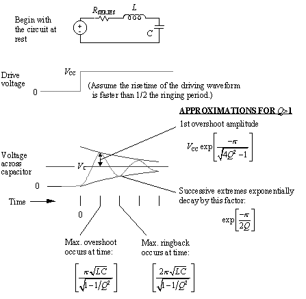
Now let's move on to a different problem. Figure 1.4 provides some useful approximations for the maximum degree of overshoot expected when a resonant circuit is driven by a step input .
Figure 1.4. The higher the Q, the greater the overshoot.

As illustrated in Figure 1.4, the higher the Q , the greater the overshoot. For Q of 1/2 or below the circuit is over-damped and no visible overshoot occurs. Values of Q greater than 1/2 create overshoot. These approximations apply to any resonant circuit that has unit response at DC and is possessed of only one main resonance, at a frequency well below the knee frequency of the driving step source, with a Q greater than one.
An excessive value of R SERIES pushes the Q below 1/2, giving the circuit a sluggish , overdamped response. The overdamped response in such a circuit is dominated by the action of the resistor R SERIES charging the capacitor. Given particular values of L and C , the best choice of R SERIES for digital applications is usually whatever value forces Q closest to unity. That gives the best risetime without undue amounts of overshoot. In other applications, such as the feedback filter for a control system, one might strive for a Q somewhat below 1/2.
Occasionally you will encounter an LC tank circuit driven by a current source and loaded by some parallel resistance. For a single resistance in parallel with the resonant elements, the Q equals
Equation 1.19

For any LC resonator that includes series and parallel elements, the inverses of the Q 's add
Equation 1.20

Distributed transmission lines also harbor resonant modes. As in all resonance problems, they are caused by multiple reservoirs of energy coupled together with a low-loss mechanism.
To understand the energy reservoir formations along a transmission line, imagine a line driven with a specific risetime t r . Every point p n along the line is surrounded by a quantity of dielectric medium that serves as a storage repository for electric field energy. It is also surrounded by a magnetically permeable medium that serves as a storage repository for magnetic field energy. In circuit terms, the voltage and current at point p n form two independent circuit variables , each of which can serve as an energy storage reservoir. Therefore, every transmission line has at least two energy storage reservoirs.
Furthermore, if two points p n and p m along the line are separated by a delay greater than t r , then over a scale of time commensurate with one rising edge, they each represent distinct, uncoupled, independent energy storage reservoirs. The longer the line, the more independent reservoirs exist and the more possibilities develop for resonant behavior.
Common strategies for combating resonance in transmission lines are threefold. Combinations of the three techniques are often employed.
- Shrink the line until it is very short, with a delay much shorter than a rising edge. This couples together all the voltages and all the currents along the line so that they can no longer independently vary without influencing each other. Any reasonable real-valued impedance at one end of the line will then fix the global relationship between the voltage and current, nailing them inextricably together. If done properly, the line will be reduced to a system that for all practical purposes possesses only one energy reservoir and therefore cannot resonate.
- Terminate the transmission line at one end, the other, or both, using a resistance equal to the characteristic impedance of the line. The termination absorbs part of the power within line, effectively reducing the circuit Q to a very low value. Low- Q circuits cannot resonate.
- Add sufficient distributed loss along the transmission line to control the Q . This can be done by selecting the conductor geometry and materials such that the skin-effect resistance is sufficient to do the job or by manipulating the dielectric losses of the substrate.
POINT TO REMEMBER
- Low- Q , dissipative circuits can't resonate. This is a desirable feature for a digital transmission path .
Fundamentals
- Impedance of Linear, Time-Invariant, Lumped-Element Circuits
- Power Ratios
- Rules of Scaling
- The Concept of Resonance
- Extra for Experts: Maximal Linear System Response to a Digital Input
Transmission Line Parameters
- Transmission Line Parameters
- Telegraphers Equations
- Derivation of Telegraphers Equations
- Ideal Transmission Line
- DC Resistance
- DC Conductance
- Skin Effect
- Skin-Effect Inductance
- Modeling Internal Impedance
- Concentric-Ring Skin-Effect Model
- Proximity Effect
- Surface Roughness
- Dielectric Effects
- Impedance in Series with the Return Path
- Slow-Wave Mode On-Chip
Performance Regions
- Performance Regions
- Signal Propagation Model
- Hierarchy of Regions
- Necessary Mathematics: Input Impedance and Transfer Function
- Lumped-Element Region
- RC Region
- LC Region (Constant-Loss Region)
- Skin-Effect Region
- Dielectric Loss Region
- Waveguide Dispersion Region
- Summary of Breakpoints Between Regions
- Equivalence Principle for Transmission Media
- Scaling Copper Transmission Media
- Scaling Multimode Fiber-Optic Cables
- Linear Equalization: Long Backplane Trace Example
- Adaptive Equalization: Accelerant Networks Transceiver
Frequency-Domain Modeling
- Frequency-Domain Modeling
- Going Nonlinear
- Approximations to the Fourier Transform
- Discrete Time Mapping
- Other Limitations of the FFT
- Normalizing the Output of an FFT Routine
- Useful Fourier Transform-Pairs
- Effect of Inadequate Sampling Rate
- Implementation of Frequency-Domain Simulation
- Embellishments
- Checking the Output of Your FFT Routine
Pcb (printed-circuit board) Traces
- Pcb (printed-circuit board) Traces
- Pcb Signal Propagation
- Limits to Attainable Distance
- Pcb Noise and Interference
- Pcb Connectors
- Modeling Vias
- The Future of On-Chip Interconnections
Differential Signaling
- Differential Signaling
- Single-Ended Circuits
- Two-Wire Circuits
- Differential Signaling
- Differential and Common-Mode Voltages and Currents
- Differential and Common-Mode Velocity
- Common-Mode Balance
- Common-Mode Range
- Differential to Common-Mode Conversion
- Differential Impedance
- Pcb Configurations
- Pcb Applications
- Intercabinet Applications
- LVDS Signaling
Generic Building-Cabling Standards
- Generic Building-Cabling Standards
- Generic Cabling Architecture
- SNR Budgeting
- Glossary of Cabling Terms
- Preferred Cable Combinations
- FAQ: Building-Cabling Practices
- Crossover Wiring
- Plenum-Rated Cables
- Laying Cables in an Uncooled Attic Space
- FAQ: Older Cable Types
100-Ohm Balanced Twisted-Pair Cabling
- 100-Ohm Balanced Twisted-Pair Cabling
- UTP Signal Propagation
- UTP Transmission Example: 10BASE-T
- UTP Noise and Interference
- UTP Connectors
- Issues with Screening
- Category-3 UTP at Elevated Temperature
150-Ohm STP-A Cabling
- 150-Ohm STP-A Cabling
- 150- W STP-A Signal Propagation
- 150- W STP-A Noise and Interference
- 150- W STP-A: Skew
- 150- W STP-A: Radiation and Safety
- 150- W STP-A: Comparison with UTP
- 150- W STP-A Connectors
Coaxial Cabling
- Coaxial Cabling
- Coaxial Signal Propagation
- Coaxial Cable Noise and Interference
- Coaxial Cable Connectors
Fiber-Optic Cabling
- Fiber-Optic Cabling
- Making Glass Fiber
- Finished Core Specifications
- Cabling the Fiber
- Wavelengths of Operation
- Multimode Glass Fiber-Optic Cabling
- Single-Mode Fiber-Optic Cabling
Clock Distribution
- Clock Distribution
- Extra Fries, Please
- Arithmetic of Clock Skew
- Clock Repeaters
- Stripline vs. Microstrip Delay
- Importance of Terminating Clock Lines
- Effect of Clock Receiver Thresholds
- Effect of Split Termination
- Intentional Delay Adjustments
- Driving Multiple Loads with Source Termination
- Daisy-Chain Clock Distribution
- The Jitters
- Power Supply Filtering for Clock Sources, Repeaters, and PLL Circuits
- Intentional Clock Modulation
- Reduced-Voltage Signaling
- Controlling Crosstalk on Clock Lines
- Reducing Emissions
Time-Domain Simulation Tools and Methods
- Ringing in a New Era
- Signal Integrity Simulation Process
- The Underlying Simulation Engine
- IBIS (I/O Buffer Information Specification)
- IBIS: History and Future Direction
- IBIS: Issues with Interpolation
- IBIS: Issues with SSO Noise
- Nature of EMC Work
- Power and Ground Resonance
Points to Remember
Appendix A. Building a Signal Integrity Department
Appendix B. Calculation of Loss Slope
Appendix C. Two-Port Analysis
- Appendix C. Two-Port Analysis
- Simple Cases Involving Transmission Lines
- Fully Configured Transmission Line
- Complicated Configurations
Appendix D. Accuracy of Pi Model
Appendix E. erf( )
Notes
EAN: N/A
Pages: 163
 .
.