Documentation Beyond Views
In many ways, an architecture is to a system what a map of the world is to the world. Thus far, we have focused on capturing the various architectural views of a system, which tell the main story. In the words of Miles Harvey, they are the "continents, oceans, mountains, lakes, rivers, and political borders" of the complete system map that we are drawing. But we now turn to the complement of view documentation, which is capturing the information that applies to more than one view or to the documentation package as a whole. Documentation beyond views corresponds to the adornments of the map, which complete the story and without which the work is inadequate.
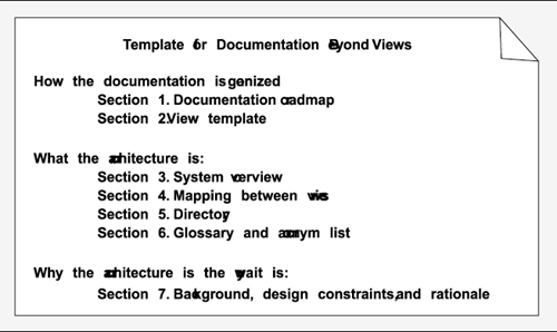
Documentation beyond views consists of three major aspects, which we can summarize as how/what/why:
- How the documentation is laid out and organized so that a stakeholder of the architecture can find the information he or she needs efficiently and reliably. This part consists of a documentation roadmap and a view template.
- What the architecture is. Here, the information that remains to be captured beyond the views themselves is a short system overview to ground any reader as to the purpose of the system, the way the views are related to one another, a list of elements and where they appear, and a glossary and an acronym list for the entire architecture.
- Why the architecture is the way it is: the background for the system, external constraints that have been imposed to shape the architecture in certain ways, and the rationale for large-scale decisions.
Figure 10.2 summarizes documentation beyond views.
Figure 10.2. Documenting information beyond views consists of how/what/why: how the documentation is laid out to serve stakeholdersa documentation roadmap and a view template; additional information beyond the views about what the architecture issystem overview, mapping between views, a directory, and a glossary; and why the architecture is the way it issystem background, design constraints, and rationale.
10.3.1 How the Documentation Is Organized to Serve a Stakeholder
Every suite of architecture documentation needs an introductory piece to explain its organization to a new stakeholder and to help that stakeholder access the information he or she is most interested in. The two kinds of how information to help an architecture stakeholder are a documentation roadmap and a view template.
Documentation Roadmap
The documentation roadmap introduces the reader to the information that the architect has chosen to include in the suite of documentation. When using the documentation as a basis for communication, a new reader needs to determine where particular information can be found. When using the documentation as a basis for analysis, a reader needs to know which views contain the information necessary for a particular analysis. A roadmap contains this information.
A roadmap consists of the following two sections:
- Description of the parts. The roadmap begins with a brief description of each part of the documentation package. Each entry may contain document information, such as the author, location, and latest version. The major part of the roadmap describes the views that the architect has included in the package. For each view, the roadmap gives
- The name of the view and what style it instantiates.
- A description of the view's element types, relation types, and property types. These descriptions can be found in the style guide from which the view was built and can be included in the roadmap directly or by reference. They let a reader begin to understand the kind of information that he or she can expect to see presented in the view.
- A description of what the view is for. Again, this information can be found in the corresponding style guide. The goal is to tell a stakeholder whether the view is likely to contain information of interest. The information can be presented by listing the stakeholders who are likely to find the view of interest, and by listing a series of questions that can be answered by examining the view.[1]
[1] ANSI/IEEE-1471-2000, the ANSI/IEEE recommended practice for architectural description for software-intensive systems, requires that the se-lected views address the concerns of at least users, acquirers, developers, and maintainers. See Section 11.6 for more information.
- A description of language, modeling techniques, or analytical methods used in constructing the view.[2]
[2] This information is also required by ANSI/IEEE-1471-2000.
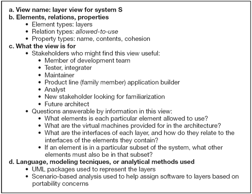
Figure 10.3 shows what a roadmap might say about a layered view for system S.
Figure 10.3. A roadmap for a layered view of system S
- How stakeholders might use the package. The roadmap follows with a section describing how various stakeholders might access the package to help address their concerns. This might include short scenarios, such as "A maintainer wishes to know the units of software that are likely to be changed by a proposed modification."
View Template
A view template is the standard organization for a view. Figure 10.1 and the material surrounding it provide a basis for a view template by defining the standard parts of a view document and the contents and rules for each part. The purpose of a view template is that of any standard organization: It helps a reader navigate quickly to a section of interest, and it helps a writer organize the information and establish criteria for knowing how much work is left to do.
10.3.2 What the Architecture Is
System Overview
This is a short prose description of the system's function, its users, and any important background or constraints. The purpose is to provide readers with a consistent mental model of the system and its purpose.
The system overview is, strictly speaking, not part of the architecture and does not contain architectural information but is indispensable for understanding the architecture. If an adequate system overview exists elsewhere, such as in the overall project documentation, a pointer to it is sufficient.
Mapping Between Views
Because all the views of an architecture describe the same system, it stands to reason that any two views will have much in common. Helping a reader or other consumer of the documentation understand the relationship between views will help that reader gain a powerful insight into how the architecture works as a unified conceptual whole. Being clear about the relationship by providing mappings between views is the key to increasing understanding and to decreasing confusion.
The mappings in a particular architecture are often complicated. For instance, each module may map to multiple runtime elements, such as when classes map to objects. Complications arise when the mappings are not one-to-one or when runtime elements of the system do not exist as code elements at all, such as when they are imported at runtime or incorporated at build or load time. These are relatively simple none- or one-to-many mappings. But in general, parts of the elements in one view can map to parts of elements in another view.
As discussed in Section 6.1, a view packet can sometimes point to another view packet in a different view. This is also part of the information that maps views.
Directory
The directory is an index of all the elements, relations, and properties that appear in any of the views, along with a pointer to its definition.
Glossary and Acronym List
The glossary and acronym list defines terms used in the architecture documentation that have special meaning. These lists, if they exist as part of the overall system or project documentation, may be given as pointers in the architecture package.
10.3.3 Why the Architecture Is the Way It Is: Background, Design Constraints, and Rationale
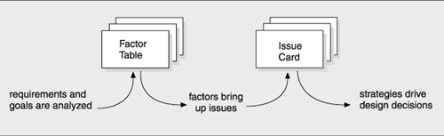
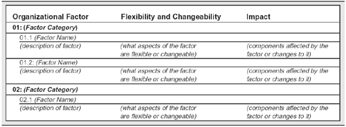
This section documents the reasoning behind decisions that apply to more than one view. Prime candidates include documentation of background or organizational constraints that led to decisions of systemwide import.
|
By now, you may realize that rationale is an important ingredient in the mix of architecture documentation, for this is the third place in the documentation package where it enjoys a reserved section. (The first place is in the documentation for an interface, see Chapter 7, and a second is in the template for a view, shown in Figure 10.1.) Having three places in the documentation package for rationale does indeed signal its importance but also results from the fact that these are different kinds of rationale, distinguished by the scope of the design decisions to which each pertains. Rationale can apply to a single view, to the design of an interface of an individual element, or to the entire design approach. No matter what the scope, the principles about what rationale should contain and when it should be included overlap all areas.
|
Rationale is the architect's chance to explain key decisions to a skeptical audience of peers, perhaps even a future architect. The goal is to convey why the architectureor the piece of it to which the rationale appliesis in fact a good solution. The idea is to convey a vicarious appreciation of the thought process the architect went through to arrive at the decision.
Once you've decided to document a design decision, try to describe it with the following five-part outline:
- Decision: a succinct summary of the design decision.
- Constraints: the key constraints that ruled out other possibilities. The system's requirements constitute a large body of constraints but by no means all. Sometimes, a particular operating system must be used; other times, a particular middleware system; at other times, the components derived from legacy systems. Perhaps there were funding pressures, or a particular commercial component was chosen because of the organization's relationship with its vendor. Perhaps key stakeholders wielded influence that affected the design. Business goals, such as time to market, often influence an architecture, as do quality attribute goals, such as modifiability, that are not always documented in a system's requirements. Some design choices result from constraints generated by other design decisions and from trade-offs with other solutions.
- Alternatives: the options you considered and the reasons for ruling them out. The reasons need not be technical: A future architect will especially appreciate your insights about what dead ends to avoid, as well as your candor if you think you made the wrong decision or if you could just as well have adopted another approach.
- Effects: the implications or ramifications of the decision. For example, what constraints does the decision impose on downstream developers, users, maintainers, testers, or builders of other interacting systems?
- Evidence: any confirmation that the decision was a good one. For example, you can explain how the design choice meets the requirements or satisfies constraints. There are various frameworks for reasoning about quality attributes, such as rate-monotonic analysis and queuing models. Use cases and quality scenarios are also used to evaluate the architecture with respect to the requirements.
Like all documentation, rationale is subject to a cost/benefit equation. But know this: Most rationale is read and used by the person who wrote it in the first place, often after weeks rather than years. So if you're altruistic, write rationale as your legacy for the next generation. If you're more motivated by interests closer to home, remember that the time it saves may be your own.
Software Architectures and Documentation
- P.1. The Role of Architecture
- P.2. Uses of Architecture Documentation
- P.3. Interfaces
- P.4. Views
- P.5. Viewtypes and Styles
- P.6. Seven Rules for Sound Documentation
- P.7. Summary Checklist
- P.8. Discussion Questions
- P.9. For Further Reading
Part I. Software Architecture Viewtypes and Styles
The Module Viewtype
- Overview
- Elements, Relations, and Properties of the Module Viewtype
- What the Module Viewtype Is For and What Its Not For
- Notations for the Module Viewtype
- Relation to Other Viewtypes
- Summary Checklist
- Discussion Questions
- For Further Reading
Styles of the Module Viewtype
- Styles of the Module Viewtype
- Decomposition Style
- Uses Style
- Generalization Style
- Layered Style
- Summary Checklist
- Discussion Questions
- For Further Reading
The Component-and-Connector Viewtype
- Overview
- Elements, Relations, and Properties of the C&C Viewtype
- What the C&C Viewtype Is For and What Its Not For
- Relation to Other Viewtypes
- Summary Checklist
- Discussion Questions
- For Further Reading
Styles of the Component-and-Connector Viewtype
- Styles of the Component-and-Connector Viewtype
- The Pipe-and-Filter Style
- Shared-Data Style
- Publish-Subscribe Style
- Client-Server Style
- Peer-to-Peer Style
- Communicating-Processes Style
- Notations for C&C Styles
- Summary Checklist
- Discussion Questions
- For Further Reading
The Allocation Viewtype and Styles
- Overview
- Elements, Relations, and Properties of the Allocation Viewtype
- Deployment Style
- Implementation Style
- Work Assignment Style
- Summary Checklist
- Discussion Questions
- For Further Reading
Part II. Software Architecture Documentation in Practice
- Part II. Software Architecture Documentation in Practice
- ECS Architecture Documentation Roadmap
- ECS System Overview
- ECS Software Architecture View Template
- Mapping Between Views
- Directory
- Architecture Glossary and Acronym List
- Module Decomposition View
- Module Uses View
- Module Generalization View
- Module Layered View
- C&C Pipe-and-Filter View
- C&C Shared-Data View
- C&C Communicating-Processes View
- Allocation Deployment View
- Allocation Implementation View
- Allocation Work Assignment View
Advanced Concepts
- Advanced Concepts
- Chunking Information: View Packets, Refinement, and Descriptive Completeness
- Using Context Diagrams
- Combined Views
- Documenting Variability and Dynamism
- Creating and Documenting a New Style
- Summary Checklist
- Discussion Questions
- For Further Reading
Documenting Software Interfaces
- Overview
- Interface Specifications
- A Standard Organization for Interface Documentation
- Stakeholders of Interface Documentation
- Notation for Interface Documentation
- Examples of Interface Documentation
- Summary Checklist
- Discussion Questions
- For Further Reading
Documenting Behavior
- Beyond Structure
- Where to Document Behavior
- Why to Document Behavior
- What to Document
- How to Document Behavior: Notations and Languages
- Summary Checklist
- Discussion Questions
- For Further Reading
Choosing the Views
- Choosing the Views
- Stakeholders and Their Documentation Needs
- Making the Choice
- Two Examples
- Summary Checklist
- Discussion Questions
- For Further Reading
Building the Documentation Package
- Building the Documentation Package
- One Document or Several?
- Documenting a View
- Documentation Beyond Views
- Validating Software Architecture Documentation
- Summary Checklist
- Discussion Questions
- For Further Reading
Other Views and Beyond
- Other Views and Beyond
- Overview
- Rational Unified Process/Kruchten 4+1
- UML
- Siemens Four Views
- C4ISR Architecture Framework
- ANSI/IEEE-1471-2000
- Data Flow and Control Flow
- RM-ODP
- Where Architecture Documentation Ends
- A Final Word
- For Further Reading
- Appendix A. Excerpts from a Software Architecture Documentation Package
- Volume I ECS Software Architecture Documentation Beyond Views
Rationale, Background, and Design Constraints
References
EAN: 2147483647
Pages: 152
