Powering the Cisco IP Phone
Most Cisco IP Phone models are capable of using the following three options for power:
- PoE With PoE, the phone plugs into the data jack that connects to the switch, and the user PC in turn connects to the IP Phone. Power-sourcing equipment (PSE), such as Cisco Catalyst PoE-capable modular and fixed-configuration switches, insert power over the Ethernet cable to the powered device, for example, an IP Phone or 802.11 wireless access point.
- Midspan power injection Because many switches do not support PoE, the powered device must support a midspan power source. This midspan device sits between the LAN switch and the powered device and inserts power on the Ethernet cable to the powered device. A technical difference between the midspan and inline power mechanism is that power is delivered on the spare pairs (pins 4, 5, 7, and 8). An example of midspan PSE is a Cisco Catalyst Inline Power Patch Panel.
- Wall power Wall power needs a DC converter for connecting the IP Phone to a wall outlet.
Note
You must order the wall power supply separately from the Cisco IP Phone. This can increase the cost of the end devices significantly. Before you decide to use wall power rather than PoE to power the Cisco IP Phones, be sure to verify the total cost of this decision.
Two Types of PoE Delivery
Cisco provides two types of inline power delivery: the Cisco original implementation and the IEEE 802.3af PoE standard. You can refer to both inline power types as PoE.
Because Cisco was the first to develop PoE, there was not an established PoE industry standard to which Cisco could conform. Because of this, the industry considers Cisco's original implementation PoE as prestandard and proprietary. Although Cisco will eventually discontinue this prestandard implementation, Cisco devices will continue to support it for many years to come. The Cisco prestandard PoE implementation supports the following features:
- Provides 48 V DC at up to 6.3 to 7.7 watts (W) per port over data pins 1, 2, 3, and 6.
- Supports most PoE-capable Cisco devices (IP Phones and wireless access points).
- Uses a Cisco proprietary method of determining whether an attached device requires power. Power is delivered only to devices that require power.
Since first developing PoE, Cisco has been driving the evolution of this technology toward standardization by working with the IEEE and member vendors to create a standards-based means of providing power from an Ethernet switch port. The IEEE 802.3af committee has ratified this capability. The IEEE 802.3af PoE standard supports the following features:
- Specifies 48 V DC at up to 15.4 W per port over data pins 1, 2, 3, and 6 or the spare pins 4, 5, 7, and 8 (a PSE can use one or the other, but not both).
- Enables a new range of Ethernet-powered devices that consume additional power.
- Standardizes the method of determining whether an attached device requires power. The PSE delivers power only to devices that require power. This type has several optional elements, such as power classification, where powered devices can optionally support a signature that defines the maximum power requirement. PSE that supports power classification reads this signature and budgets the correct amount of power per powered device, which will likely be significantly less than the maximum allowed power.
Without power classification, the switch reserves the full 15.4 W of power for every device. This behavior might result in oversubscription of the available power supplies so that some devices will not be powered even though there is sufficient power available.
Power classification defines these five classes:
0 (default) 15.4 W reserved
1 4 W
2 7 W
3 15.4 W
4 Reserved for future expansion
All Cisco IEEE 802.3af-compliant switches support power classification.
Tip
The Cisco Power Calculator is an online tool that enables you to calculate the power supply requirements for a specific PoE configuration. The Cisco Power Calculator is available to registered Cisco.com users at www.cisco.com/go/poe.
PoE Device Detection
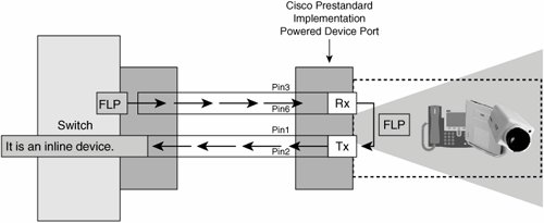
The Cisco prestandard PoE and industry standard IEEE 802.3af PoE have slightly different methods of detecting an inline power-capable device. Figure 8-1 illustrates how a Cisco prestandard Catalyst switch detects a Cisco IP Phone, wireless access point, or other inline power-capable device. When a switch port that is configured for inline power detects a connected device, the switch sends an Ethernet Fast Link Pulse (FLP) to the device. The Cisco powered device (IP Phone) loops the FLP back to the switch to indicate its inline power capability. The switch then delivers 48 V DC PoE (inline) power to the IP Phone or other inline power-capable endpoint.
Figure 8-1. Cisco Prestandard PoE Device Detection
A Cisco Catalyst IEEE 802.3af-compliant switch detects a Cisco IP Phone, wireless access point, or other inline power-capable device through a very similar process. The PSE (Cisco Catalyst switch) detects a powered device by applying a voltage in the range of 2.8 V to 10 V on the cable and then looks for a 25K ohm signature resistor rather than using the Cisco proprietary FLP signal. Compliant powered devices must support this resistance method. If the appropriate resistance is found, the Cisco Catalyst switch delivers power.
Catalyst Family of PoE Switches
The Cisco Catalyst LAN switching portfolio is the industry-leading family of intelligent switching solutions delivering a robust range of security and quality of service (QoS) capabilities. The Cisco Catalyst switch portfolio allows organizations to enable new business applications and integrate new technologies such as wireless and IP telephony into their network infrastructure. Here are the switches in the Cisco Catalyst family:
- Cisco Catalyst modular switching The Cisco Catalyst 6500 Series delivers a 96-port 10BASE-T/100BASE-T line card and 48-port 10BASE-T/100BASE-T and 10BASE-T/100BASE-T/1000BASE-T line cards. The Catalyst 6500 Series offers a modular PoE daughter card architecture for the 96-port card and the 48-port 10/100/1000 card. The Cisco Catalyst 4500 Series delivers 48-port 10/100 and 10/100/1000 line cards. All line cards support both IEEE 802.3af and Cisco prestandard inline power. The cards are compatible with any Cisco Catalyst 6500 or 4500 chassis and Supervisor Engine. The Cisco Catalyst modular chassis switches can deliver 15.4 W per port for all 48 ports on a module simultaneously.
- Cisco Catalyst stackable switching The Cisco Catalyst 3750 Series offers 48- and 24-port Fast Ethernet switches that comply with IEEE 802.3af and Cisco prestandard PoE. The Cisco Catalyst 3560 Series offers 48- and 24-port Fast Ethernet switches that support both the industry standard and Cisco standard PoE.
- Cisco EtherSwitch modules The Cisco 36- and 16-port 10/100 EtherSwitch modules for Cisco 2600 and 3700 Series routers offer branch office customers the option to integrate switching and routing in one platform. These modules can support Cisco prestandard PoE and provide straightforward configuration, easy deployment, and integrated management in a single platform. The Cisco 2600 Series requires a separate external PoE power supply; the Cisco 3700 Series integrates the power supply. Cisco has also released EtherSwitch modules for the newer Integrated Service Routers (ISRs). These new EtherSwitch modules support both the Cisco prestandard PoE and the IEEE 802.3af PoE.
Table 8-1 lists the Cisco Catalyst PoE options.
|
PoE Option |
Cisco Catalyst 6500 |
Cisco Catalyst 4500 |
Cisco Catalyst 3750 |
Cisco Catalyst 3560 |
Cisco EtherSwitch Module |
|---|---|---|---|---|---|
|
PoE Configuration Options |
48-, 96-port 10/100 or 48-port 10/100/1000 |
48-port 10/100 or 10/100/1000 |
24-, 48-port 10/100 |
24-, 48-port 10/100 |
16-, 36-port 10/100 |
|
IEEE 802.3af-Compliant |
Yes |
Yes |
Yes |
Yes |
No (older series) Yes (ISRs) |
|
Cisco Prestandard PoE |
Yes |
Yes |
Yes |
Yes |
Yes |
Tip
The switches that are listed here also support multiple VLANs per port and QoS capabilities.
Note
The pace of change in IP telephony is intense. By the time you are reading this text, Cisco will have most likely introduced multiple new product lines and switch models that support PoE and many other features. Always be sure to check the Cisco website for the latest product information.
Configuring PoE
By default, PoE is enabled on all Cisco devices that support the PoE feature. The default mode for PoE is auto, which means the switch will automatically detect if a device is PoE capable and supply power, if necessary. If you are using a switch that is running Cisco Catalyst Operating System software (CatOS), use the following syntax to modify the default PoE settings:
CatOS>(enable) set port inlinepower <mod/port> ?
 auto Port inline power auto mode
 off Port inline power off mode
The two modes are auto and off. In the off mode, the switch does not power up the port even if an unpowered phone is connected. In the auto mode, the switch powers up the port only if the switching module has discovered the phone. Examples of devices running Cisco CatOS include the Cisco Catalyst 6500, 4500, and 4000 Series.
Tip
It can be useful to turn PoE capabilities off on ports that you are sure will never use the feature. If the power supply your switch is equipped with is unable to extend power to all ports, you can specify ports that should receive power. Otherwise, the switch will allocate power to ports with lower port numbers until it exhausts the available power supply leaving the higher port numbers unpowered. The switch allocates power to ports configured with the "auto" setting regardless of whether the port is using the power.
If you are using a switch that is running Cisco IOS (NativeIOS), use the following syntax to modify the default PoE settings:
NativeIOS(config-if)# power inline [auto | never]
Use the power inline command on switches that are running native Cisco IOS software (examples include the Catalyst 6500, 4500, 3750, and 3560 switches). The powered device-discovery algorithm is operational in the auto mode. The powered device-discovery algorithm is disabled in the never mode. Other modes exist for allocating power, depending on the version of Cisco IOS, for example, the ability to allocate power on a per-port basis with the allocation milliwatt command.
Note
The Catalyst 6500 Series can run either Cisco Catalyst Operating System software or native Cisco IOS software if the switch Supervisor Engine has a Multilayer Switch Feature Card (MSFC). Otherwise, these switches can run only Cisco Catalyst software. The Cisco Catalyst 4500 and 4000 Series can also run Cisco Catalyst software or native Cisco IOS software, depending on the Supervisor Engine. Generally, late-edition Supervisor Engines run native Cisco IOS software; however, you should check the product documentation to determine the Supervisor Engine and the operating system that is supported on your specific model.
Verifying PoE
You can use the following command to display a view of the power allocated on Cisco Catalyst switches running the CatOS:
CatOS>(enable) show port inline power 7
Default Inline Power allocation per port: 10.000 Watts (0.23 Amps @42V)
Total inline power drawn by module 7: 75.60 Watts (1.80 Amps @42V)
Port InlinePowered PowerAllocated
 Admin Oper Detected mWatt mA @42V
---- ----- ---- -------- --------- -----------
7/1 auto off no 0 0
7/2 auto on yes 6300 150
7/3 auto on yes 6300 150
7/4 auto off no 0 0
7/5 auto off no 0 0
7/6 auto off no 0 0
7/7 auto off no 0 0
You can use the following command to display a view of the power allocated on Cisco Catalyst switches running the NativeIOS:
NativeIOS#show power inline
Available:360(w) Used:22(w) Remaining:338(w)

Interface Admin Oper Power Device Class Max
--------- ------ ---------- ------- ------------------- ----- ----
Fa0/1 auto off 0.0 n/a n/a 15.4
Fa0/2 auto off 0.0 n/a n/a 15.4
Fa0/3 auto off 0.0 n/a n/a 15.4
Fa0/4 auto off 0.0 n/a n/a 15.4
Fa0/5 auto off 0.0 n/a n/a 15.4
Fa0/6 auto off 0.0 n/a n/a 15.4
Fa0/7 auto off 0.0 n/a n/a 15.4
Fa0/8 auto on 10.3 IP Phone 7970 15.4
Fa0/9 auto off 0.0 n/a n/a 15.4
Fa0/10 auto on 6.3 IP Phone 7960 n/a 15.4
Fa0/11 auto off 0.0 n/a n/a 15.4
Fa0/12 auto off 0.0 n/a n/a 15.4
Fa0/13 auto off 0.0 n/a n/a 15.4
Fa0/14 auto on 6.3 IP Phone 7960 n/a 15.4
Table 8-2 provides a brief description of the output.
|
Output |
Description |
|
|---|---|---|
|
Port |
Identifies the port number on the module |
|
|
Inline Powered |
Admin |
Identifies the port configuration from using the set inlinepower mod/port [auto | off] command |
|
Oper |
Identifies whether the inline power is operational |
|
|
Power Allocated |
Detected |
Identifies whether power is detected |
|
mWatt/Watts |
Identifies the milliwatts (CatOS) or Watts (NativeIOS) supplied on a given port |
|
|
mA @42V |
Identifies the milliamps at 42 V supplied on a given port (the actual voltage is 48 V) |
|
Part I: Cisco CallManager Fundamentals
Introduction to Cisco Unified Communications and Cisco Unified CallManager
Cisco Unified CallManager Clustering and Deployment Options
- Cisco Unified CallManager Clustering and Deployment Options
- The Two Sides of the Cisco Unified CallManager Cluster
- Cluster Redundancy Designs
- Call-Processing Deployment Models
- Summary
- Review Questions
Cisco Unified CallManager Installation and Upgrades
- Cisco Unified CallManager Installation and Upgrades
- Cisco Unified CallManager 4.x Clean Installation Process
- Upgrading Prior Cisco Unified CallManager Versions
- Summary
- Review Questions
Part II: IPT Devices and Users
Cisco IP Phones and Other User Devices
Configuring Cisco Unified CallManager to Support IP Phones
- Configuring Cisco Unified CallManager to Support IP Phones
- Configuring Intracluster IP Phone Communication
- IP Phone Configuration
- Case Study: Device Pool Design
- Summary
- Review Questions
Cisco IP Telephony Users
- Cisco IP Telephony Users
- Cisco CallManager User Database
- Cisco CallManager User Configuration
- User Logon and Device Configuration
- Summary
- Review Questions
Cisco Bulk Administration Tool
- Cisco Bulk Administration Tool
- The Cisco Bulk Administration Tool
- Using the Tool for Auto-Registered Phone Support
- Summary
- Review Questions
Part III: IPT Network Integration and Route Plan
Cisco Catalyst Switches
- Cisco Catalyst Switches
- Catalyst Switch Role in IP Telephony
- Powering the Cisco IP Phone
- Data and Voice VLANs
- Configuring Class of Service
- Summary
- Review Questions
Configuring Cisco Gateways and Trunks
- Configuring Cisco Gateways and Trunks
- Cisco Gateway Concepts
- Configuring Access Gateways
- Cisco Trunk Concepts
- Configuring Intercluster Trunks
- SIP and Cisco CallManager
- Summary
- Review Questions
Cisco Unified CallManager Route Plan Basics
- Cisco Unified CallManager Route Plan Basics
- External Call Routing
- Route Plan Configuration Process
- Summary
- Review Questions
Cisco Unified CallManager Advanced Route Plans
- Cisco Unified CallManager Advanced Route Plans
- Route Filters
- Discard Digit Instructions
- Transformation Masks
- Translation Patterns
- Route Plan Report
- Summary
- Review Questions
Configuring Hunt Groups and Call Coverage
- Configuring Hunt Groups and Call Coverage
- Call Distribution Components
- Configuring Line Groups, Hunt Lists, and Hunt Pilots
- Summary
- Review Questions
Implementing Telephony Call Restrictions and Control
- Implementing Telephony Call Restrictions and Control
- Class of Service Overview
- Partitions and Calling Search Spaces Overview
- Time-of-Day Routing Overview
- Configuring Time-of-Day Routing
- Time-of-Day Routing Usage Scenario
- Summary
- Review Questions
Implementing Multiple-Site Deployments
- Implementing Multiple-Site Deployments
- Call Admission Control
- Survivable Remote Site Telephony
- Summary
- Review Questions
Part IV: VoIP Features
Media Resources
- Media Resources
- Introduction to Media Resources
- Conference Bridge Resources
- Media Termination Point Resources
- Annunciator Resources
- Transcoder Resources
- Music on Hold Resources
- Media Resource Management
- Summary
- Review Questions
Configuring User Features, Part 1
- Configuring User Features, Part 1
- Basic IP Phone Features
- Softkey Templates
- Enhanced IP Phone Features
- Barge and Privacy
- IP Phone Services
- Summary
- Review Questions
Configuring User Features, Part 2
- Configuring User Features, Part 2
- Cisco CallManager Extension Mobility
- Client Matter Codes and Forced Authentication Codes
- Call Display Restrictions
- Malicious Call Identification
- Multilevel Precedence and Preemption
- Summary
- Review Questions
Configuring Cisco Unified CallManager Attendant Console
- Configuring Cisco Unified CallManager Attendant Console
- Introduction to Cisco CallManager Attendant Console
- Call Routing and Call Queuing
- Server and Administration Configuration
- Cisco Attendant Console Features
- Summary
- Review Questions
Configuring Cisco IP Manager Assistant
- Configuring Cisco IP Manager Assistant
- Cisco IP Manager Assistant Overview
- Cisco IP Manager Assistant Architecture
- Configuring Cisco IPMA for Shared-Line Support
- Summary
- Review Questions
Part V: IPT Security
Securing the Windows Operating System
- Securing the Windows Operating System
- Threats Targeting the Operating System
- Security and Hot Fix Policy
- Operating System Hardening
- Antivirus Protection
- Cisco Security Agent
- Administrator Password Policy
- Common Windows Exploits
- Security Taboos
- Summary
- Review Questions
Securing Cisco Unified CallManager Administration
- Securing Cisco Unified CallManager Administration
- Threats Targeting Remote Administration
- Securing CallManager Communications Using HTTPS
- Multilevel Administration
- Summary
- Review Questions
Preventing Toll Fraud
- Preventing Toll Fraud
- Toll Fraud Exploits
- Preventing Call Forward and Voice-Mail Toll Fraud Using Calling Search Spaces
- Blocking Commonly Exploited Area Codes
- Using Time-of-Day Routing
- Using FAC and CMC
- Restricting External Transfers
- Dropping Conference Calls
- Summary
- Review Questions
Hardening the IP Phone
Understanding Cryptographic Fundamentals
- Understanding Cryptographic Fundamentals
- What Is Cryptography?
- Symmetric Encryption
- Asymmetric Encryption
- Hash Functions
- Digital Signatures
- Summary
- Review Questions
Understanding the Public Key Infrastructure
- Understanding the Public Key Infrastructure
- The Need for a PKI
- PKI as a Trusted Third-Party Protocol
- PKI Entities
- PKI Enrollment
- PKI Revocation and Key Storage
- PKI Example
- Summary
- Review Questions
Understanding Cisco IP Telephony Authentication and Encryption Fundamentals
- Understanding Cisco IP Telephony Authentication and Encryption Fundamentals
- Threats Targeting the IP Telephony System
- How CallManager Protects Against Threats
- PKI Topologies in Cisco IP Telephony
- PKI Enrollment in Cisco IP Telephony
- Keys and Certificate Storage in Cisco IP Telephony
- Authentication and Integrity
- Encryption
- Summary
- Review Questions
Configuring Cisco IP Telephony Authentication and Encryption
- Configuring Cisco IP Telephony Authentication and Encryption
- Authentication and Encryption Configuration Overview
- Enabling Services Required for Security
- Using the CTL Client
- Working with Locally Significant Certificates
- Configuring the Device Security Mode
- Negotiating Device Security Mode
- Generating a CAPF Report
- Summary
- Review Questions
Part VI: IP Video
Introducing IP Video Telephony
- Introducing IP Video Telephony
- IP Video Telephony Solution Components
- Video Call Concepts
- Video Protocols Supported in Cisco CallManager
- Bandwidth Management
- Call Admission Control Within a Cluster
- Call Admission Control Between Clusters
- Summary
- Review Questions
Configuring Cisco VT Advantage
- Configuring Cisco VT Advantage
- Cisco VT Advantage Overview
- How Calls Work with Cisco VT Advantage
- Configuring Cisco CallManager for Video
- Configuring Cisco IP Phones for Cisco VT Advantage
- Installing Cisco VT Advantage on a Client
- Summary
- Review Questions
Part VII: IPT Management
Introducing Database Tools and Cisco Unified CallManager Serviceability
- Introducing Database Tools and Cisco Unified CallManager Serviceability
- Database Management Tools
- Cisco CallManager Serviceability Overview
- Tools Overview
- Summary
- Review Questions
Monitoring Performance
- Monitoring Performance
- Performance Counters
- Microsoft Event Viewer
- Microsoft Performance Monitor
- Real-Time Monitoring Tool Overview
- Summary
- Review Questions
Configuring Alarms and Traces
- Configuring Alarms and Traces
- Alarm Overview
- Alarm Configuration
- Trace Configuration
- Trace Analysis
- Trace Collection
- Bulk Trace Analysis
- Additional Trace Tools
- Summary
- Review Questions
Configuring CAR
- Configuring CAR
- CAR Overview
- CAR Configuration
- Report Scheduling
- System Database Configuration
- User Report Configuration
- Summary
- Review Questions
Using Additional Management and Monitoring Tools
- Using Additional Management and Monitoring Tools
- Remote Management Tools
- Dependency Records
- Password Changer Tool
- Cisco Dialed Number Analyzer
- Quality Report Tool
- Summary
- Review Questions
Part VIII: Appendix
Appendix A. Answers to Review Questions
Index
EAN: 2147483647
Pages: 329
