Configuring Intracluster IP Phone Communication
Unbelievably, you can have an entire Cisco IP telephony network deployed in a matter of seconds using the Cisco CallManager in its base configuration. However, setting up the voice network correctly can take a considerable amount of planning and configuration. Thankfully, this chapter shows you how to set up the network manually, and then shows you how to pull it off automatically in a matter of seconds.
Removing DNS Reliance
Chapter 4 discussed the boot process of a Cisco IP Phone. It is critical to understand that process to effectively troubleshoot the IP telephony network. Just to review, the following are three of the critical steps in the process:
|
1. |
Cisco IP Phone obtains an IP address from the DHCP server along with the IP address of the TFTP server. |
|
2. |
The Cisco IP Phone contacts the TFTP server and downloads its configuration. |
|
3. |
The Cisco IP Phone registers with the Cisco CallManager. |
These steps (along with a few others) were presented in the preceding chapter. Now you might be wondering, "The Cisco IP Phone downloads its configuration from the TFTP server. So...where does that configuration come from?" Great question! It comes from you. As you configure the Cisco CallManager, it will generate a configuration file that it places on the TFTP server for the IP Phone to download. In that configuration file will be a list of up to three Cisco CallManagers for the Cisco IP Phone to contact.
One of the most common problems that occur in the field is a Cisco IP Phone failing to register with the Cisco CallManager because it cannot resolve the Cisco CallManager's hostname to an IP address. This is because, by default, the Cisco CallManager puts a list of up to three Cisco CallManager hostnames the Cisco IP Phone can contact. If you have not configured the IP Phones for DNS name resolution (or the IP Phones cannot reach the DNS server), the phone registration will fail.
Because of this, changing the name of the selected server to the IP address of the server in the Cisco CallManager Administration window is the first step in configuring Cisco CallManager to support Cisco IP Phones.
Note
Removing DNS reliance is considered a best-practice step in configuring Cisco CallManager. If you prefer, you can keep the Cisco CallManager hostnames in the configuration and still have a functional network.
Renaming the server to the IP address has the following benefits:
- It allows IP Phones and other devices to find Cisco CallManager on the network without having to query the Domain Name System (DNS) server to help resolve the server name to an IP address.
- It prevents the IP telephony network from failing if the IP Phones lose the connection to the DNS server.
- It decreases the time that is required when a device attempts to contact Cisco CallManager.
Complete these steps to eliminate DNS reliance:
|
Step 1. |
In Cisco CallManager Administration, choose System > Server. The Find and List Servers window appears. Click Find to display a list of available servers. |
|
Step 2. |
Click a server name. The Server Configuration window appears. |
|
Step 3. |
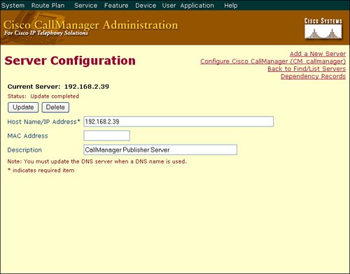
Remove the hostname and enter the IP address for the server in the Host Name/IP Address field. Click Update. |
|
Step 4. |
Repeat Steps 1-3 for every Cisco CallManager in the cluster. |
After the Cisco CallManager hostnames are changed to the appropriate IP addresses, the Cisco CallManager automatically updates the configuration file on the TFTP server, causing the IP Phones to contact the Cisco CallManagers via the IP address rather than the hostname. Figure 5-1 illustrates the Server Configuration screen.
Figure 5-1. Cisco CallManager Server Configuration Window
Note
There are other places where server names must be changed to IP addresses to fully remove DNS resolution from the cluster. Most of these can be found in the Service > Enterprise Parameters options.
Configuring Device Pools
Device pools provide a convenient way to define a set of common characteristics that can be assigned to devices, such as IP Phones, instead of assigning individual characteristics to individual phones. Device pools enable you to simply assign the phone to the device pool so that the phone automatically inherits the common configuration items. You must configure the device pool for Cisco IP Phones before adding them to the network.
To create a new device pool, you must first create (or use default settings where applicable) the following minimal mandatory components:
- Cisco CallManager group
- Date/time group
- Region
- Softkey template
- Cisco Survivable Remote Site Telephony (SRST) reference
Note
The SRST Reference field allows you to specify the IP address of the Cisco SRST router. Cisco SRST enables routers to provide call-handling support for Cisco IP Phones when they lose their connection to remote Cisco CallManager installations or when the WAN connection is down.
These components (except for the SRST reference) are covered later in this chapter. SRST is covered in Chapter 14, "Implementing Multiple-Site Deployments."
The device pool combines all of the individual configurations that you have created into a single entity. You will eventually assign this entity to individual devices, such as IP Phones. This process will configure these devices with most of the configuration elements that they need to operate efficiently in your IP telephony network.
For example, configuring 100 different Cisco IP Phones to use the Arizona time zone, the English language, and the classical-style music on hold (MOH) option is tedious. Instead, you can create a device pool, named "Arizona," that configures the correct time zone, language, and MOH, and you can make a single assignment of the Arizona device pool to each IP Phone.
Complete these steps to create the device pool:
|
Step 1. |
Choose System > Device Pool. The Find and List Device Pools window opens. |
|
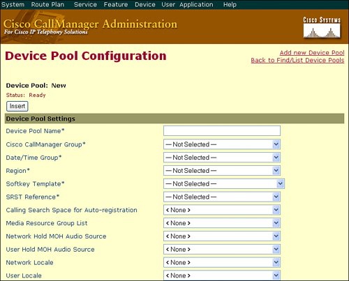
Step 2. |
Click the Add a New Device Pool link to open the Device Pool Configuration window shown in Figure 5-2. Choose, at a minimum, the Cisco CallManager group, date/time group, region, and softkey template. |
Figure 5-2. Cisco CallManager Device Pool Configuration Window
Note
It is a good practice to name your configuration components in Cisco CallManager to reflect their purpose. For example, you could name the Arizona Device Pool "Arizona_DP." You could name the Arizona Date and Time Group "Arizona_DT." This allows you to easily identify these items in the Cisco CallManager database.
You can configure many options through a device pool. Some of these options are shown here; others are fully explained later in the book. Table 5-1 provides a quick reference for each of the configuration options in the device pool.
|
Field |
Description |
|---|---|
|
Device Pool Name[*] |
Describes a name for the device pool. |
|
Cisco CallManager Group[*] |
Selects a redundancy group for the device pool. This redundancy group can contain a maximum of three redundant Cisco CallManager servers. |
|
Date/Time Group[*] |
Assigns the correct time zone to the device. |
|
Region[*] |
Determines the coder-decoder (codec) selection used by the device, depending on the end location of the call. |
|
Softkey Template[*] |
Defines the type and order of the softkeys that are displayed on the liquid crystal display (LCD) of a Cisco IP Phone. |
|
SRST Reference[*] |
Configures SRST and selects the gateway that will support the device if the connection to the Cisco CallManager is lost. |
|
Calling Search Space for Auto-registration |
Defines whom an IP Phone is able to call if it auto-registers with the Cisco CallManager. |
|
Media Resource Group List |
Assigns media resource support to a device for functions such as conferencing, transcoding, or MOH. |
|
Network Hold MOH Audio Source |
Selects the audio that Cisco CallManager should play when a user presses the Transfer or Conference button on the Cisco IP Phone. |
|
User Hold MOH Audio Source |
Selects the audio that Cisco CallManager should play when a user presses the Hold button on the Cisco IP Phone. |
|
Network Locale |
Defines the tones and cadences that the device uses. |
|
User Locale |
Defines the language that the device uses. |
|
Connection Monitor Duration |
Defines the amount of time that the IP Phone monitors its connection to Cisco CallManager before it unregisters from SRST and reregisters to Cisco CallManager. This is to ensure that the link is stable (not "flapping"). The default for the enterprise parameter specifies 120 seconds, which can be modified on a device-pool basis or left at the default value. |
|
MLPP Precedence and Preemption Information |
Manages Multilevel Precedence and Preemption (MLPP) settings: MLPP Indication: Specifies whether devices in the device pool that are capable of playing precedence tones will use the capability when the devices plan an MLPP precedence call MLPP Preemption: Specifies whether devices in the device pool that are capable of preempting calls in progress will use the capability when the devices plan an MLPP precedence call MLPP Domain: A hexadecimal value for the MLPP domain that is associated with the device pool |
[*] Indicates a required field.
If you make changes to a device pool, you must reset the devices in that device pool before the changes will take effect.
You cannot delete a device pool that has been assigned to any device or one that is used for device defaults configuration. To find out which devices are using the device pool, click the Dependency Records link in the Device Pool Configuration window. If you try to delete a device pool that is in use, an error message is displayed. Before deleting a device pool that is currently in use, you must perform one of the following tasks:
- Update the devices to assign them to a different device pool.
- Delete the devices that are assigned to the device pool that you want to delete.
Individual components of a device pool are explored in the following subtopics.
Cisco Unified CallManager Group Configuration
A Cisco CallManager group specifies a prioritized list of Cisco CallManager servers for a Cisco IP Phone to register to, with a maximum of three in the list. The first Cisco CallManager in the list serves as the primary Cisco CallManager for devices that are assigned to that group. The other members of the group serve as the secondary and tertiary backups. Changes to the Cisco CallManager group affect the configuration file that is given to Cisco IP Phones by the TFTP server when they initially boot.
Complete these steps to configure a Cisco CallManager group:
|
Step 1. |
Choose System > Cisco CallManager Group. The default group that was created by Cisco CallManager during the installation appears. |
|
Step 2. |
Choose Add New Cisco CallManager Group to create a new Cisco CallManager group. |
|
Step 3. |
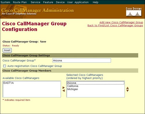
Move the "Available" Cisco CallManager servers to the "Selected" Cisco CallManagers using the left and right arrows to place them in the group. You can change the order of Cisco CallManager servers using the up and down arrows, which adjusts the priority of the Cisco CallManager servers where the top server will be the primary server of the group and the bottom server will be the tertiary server of the group. |
In Figure 5-3, you can see the Cisco CallManager group called "Arizona" has three Cisco CallManager servers. You would assign the Cisco CallManager group to a device pool, and you then assign this device pool to the Cisco IP Phone. The IP Phone uses the Arizona Cisco CallManager as its primary Cisco CallManager, the California Cisco CallManager as its secondary, and the Michigan Cisco CallManager as its tertiary. Cisco CallManager Administration will present an error message if you attempt to add a fourth Cisco CallManager (for example, the EAST1A Cisco CallManager) to the list.
Figure 5-3. Cisco CallManager Group Configuration Window
Note
The Auto-registration Cisco CallManager Group check box (shown in Figure 5-3) dictates that all devices that auto-register will receive the current Cisco CallManager Group assignment. You can only designate a single Cisco CallManager Group as the auto-registration group. Auto-registration is covered thoroughly at the end of this chapter.
Note
The sample Cisco CallManager group configuration is an example of clustering over the IP WAN because only Cisco CallManagers in the same cluster can be added to a Cisco CallManager group. More commonly, Cisco CallManager clustered servers reside in the same physical location. You can then configure Cisco CallManager groups based on the servers within your data center. For example, the server Arizona_SUB1 could be the primary, Arizona_SUB2 could be the secondary, and Arizona_PUB could be the tertiary server in a Cisco CallManager group.
Date/Time Group Configuration
Date/time groups define time zones for the various devices that are connected to Cisco CallManager. You can assign each device to only one device pool. As a result, the device has only one date/time group.
Cisco CallManager has a default date/time group called CMLocal. The CMLocal date/time group synchronizes to the active date and time of the operating system on the Cisco CallManager server. You can change the settings for CMLocal after installing Cisco CallManager.
Note
All Subscriber Cisco CallManager servers in a cluster synchronize their time with the Publisher server through a Microsoft process known as W32TIME. Cisco highly recommends using the Microsoft NTP client on the Publisher server to synchronize its time with a more accurate source.
Complete these steps to configure the date/time group:
|
Step 1. |
Choose System > Date/Time Group. The default CMLocal group appears. |
|
Step 2. |
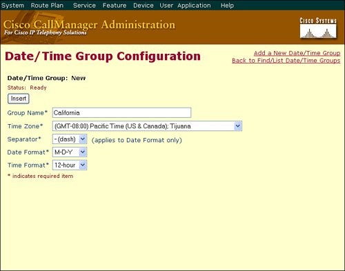
Choose Add a New Date/Time Group to insert additional date/time groups as required. |
Figure 5-4 illustrates the addition of a California date/time group.
Figure 5-4. Cisco CallManager Date/Time Group Configuration Window
Tip
For a worldwide distribution of Cisco IP Phones, you will want to create one named date/time group for each of the time zones where you have deployed Cisco IP Phones.
Region Configuration
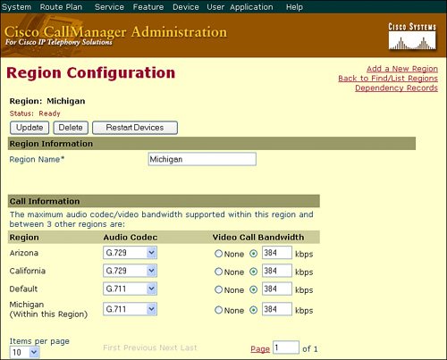
The region is typically the most confusing item of the device pool configuration. When you create a region, you specify the audio codec that can be used for calls between devices (such as IP Phones) within that region and between that region and other regions. As of Cisco CallManager Release 4.0, you can also specify the video call bandwidth.
You can create regions to modify the codec selection for any reason; however, most network administrators create regions based on geographical areas. The default voice codec for all calls through Cisco CallManager is G.711. If you do not plan to use any other voice codec, you do not need to use regions. The system will use the default region.
For example, in Figure 5-5, there are four regions: Arizona, California, Default, and Michigan; the configuration of the Michigan region is displayed. If a device that is assigned to the Michigan region calls another device in the Michigan region, the devices use the G.711 codec. However, if a device assigned to the Michigan region calls a device that is assigned to the Arizona region, the devices use the G.729 codec. Cisco CallManager creates the Default region during the installation process. You can rename the Default region to a more logical name to avoid confusion, or you can ignore it and use only regions that you have created.
Figure 5-5. Cisco CallManager Region Configuration
Complete these steps to configure a region:
|
Step 1. |
Choose System > Region. The default region that was created during the Cisco CallManager installation appears. |
|
Step 2. |
Choose Add a New Region to configure the regions, and choose the codec and video bandwidth as appropriate between the regions. Click Insert to save your changes. |
Softkey Template Configuration
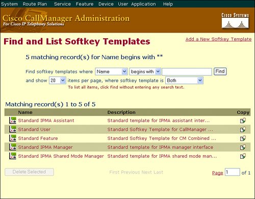
The Softkey Template Configuration window allows the administrator to manage the on-screen softkeys that the Cisco IP Phones support (such as the Cisco IP Phone 7960 and 7940 models). Softkeys govern functionality such as Hold, Conference, Transfer, and so on. You can configure these softkeys with many Cisco CallManager functions and features. You can also use the softkey templates to restrict what features the user can access. For example, if you do not want the user to have the ability to initiate conference calls, you can just remove the conference button from their softkey template.
To access the Softkey Template Configuration window, open the Cisco CallManager Administration window and choose Device > Device Settings > Softkey Templates. Cisco CallManager comes with a few default softkey templates shown in Figure 5-6, which are discussed fully in future chapters. You cannot modify or delete these default templates; however, you can make copies of them for your own use by clicking the Copy icon located to the right of the template name.
Figure 5-6. Cisco CallManager Softkey Template Configuration
After you have made a copy of the softkey template you want to use, you can modify the softkeys available, and assign the template to a device pool. The full configuration of the softkey templates are covered in future chapters.
IP Phone Button Templates
Whereas softkey templates focus on modifying the features assigned to Cisco IP Phones, the IP Phone button template focuses on assigning line and speed dial buttons to the phone. Although Cisco CallManager does not require the IP Phone button templates for the device pool, it is good to have all the button templates you plan on using created before you begin to add IP Phones to the Cisco CallManager SQL database. Figure 5-7 shows the physical buttons affected on the Cisco 7961 IP Phone.
Figure 5-7. Cisco 7961 IP Phone Softkey and Line Buttons
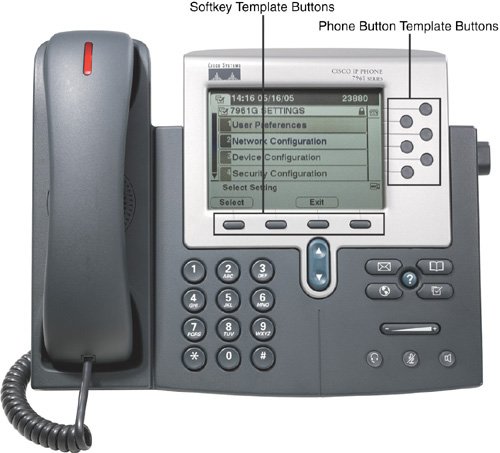
You must assign at least one line per IP Phone; usually this line is button 1. Depending on the Cisco IP Phone model, you can assign additional lines.
Before adding any IP Phones to the system, create phone button templates with all of the possible combinations for all IP Phone models. An IP Phone model can have various combinations; for example, a Cisco IP Phone 7960 supports six lines and can use the following phone button template combinations:
- One line, five speed dial buttons
- Two lines, four speed dial buttons (default)
- Three lines, three speed dial buttons
- Four lines, two speed dial buttons
- Five lines, one speed dial button
- Six lines, no speed dial button
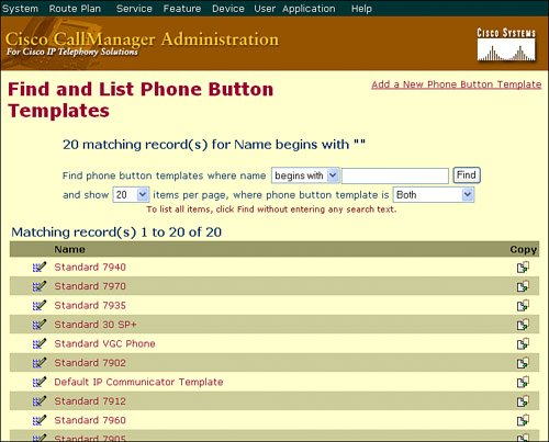
To create a phone button template from Cisco CallManager Administration, click Device > Device Settings > Phone Button Template. Click the Find button to see the default templates included with Cisco CallManager (shown in Figure 5-8).
Figure 5-8. Cisco CallManager Phone Button Template Configuration
Tip
There are additional methods to add speed dial capabilities to a Cisco IP Phone; you are not limited to just the phone button template buttons. These mechanisms are discussed in future chapters.
As with the softkey templates, you are unable to modify the default phone button templates. Rather, you can make copies of the default templates (by clicking on the Copy icon) and saving them under a unique name.
Create easily recognizable naming conventions for the phone button template. A suggested best practice is to use the model number of the Cisco IP Phone followed by the number of lines and speed dials. For example, a phone button template named "7960 1-5" would indicate a Cisco 7960 IP Phone with one line and five speed dial buttons.
Putting It All Together
The previous sections discussed creating the mandatory, minimum elements to assemble a device pool. After you have created all the individual elements you need, create device pools that group the common configuration elements together. For example, you might have the following device pool configuration:
- Device Pool Name: Arizona Phones
- Cisco CallManager Group: Arizona_CG (CCM_AZ Primary, CCM_CA Secondary)
- Date/Time Group: Arizona_DT (selects Arizona as the time zone)
- Region Configuration: Arizona_REG (selects G.711 for calls within Arizona, G.729 for calls elsewhere)
- Softkey Template: Standard User
- SRST Reference: Disable (the default, disables SRST)
You would then create additional device pools based on location, Cisco CallManager Groups, or other unique configurations. The final step is to assign the device pools to the Cisco IP Phones that will use them. As of yet, you have yet to add these IP Phones to the Cisco CallManager database.
Part I: Cisco CallManager Fundamentals
Introduction to Cisco Unified Communications and Cisco Unified CallManager
Cisco Unified CallManager Clustering and Deployment Options
- Cisco Unified CallManager Clustering and Deployment Options
- The Two Sides of the Cisco Unified CallManager Cluster
- Cluster Redundancy Designs
- Call-Processing Deployment Models
- Summary
- Review Questions
Cisco Unified CallManager Installation and Upgrades
- Cisco Unified CallManager Installation and Upgrades
- Cisco Unified CallManager 4.x Clean Installation Process
- Upgrading Prior Cisco Unified CallManager Versions
- Summary
- Review Questions
Part II: IPT Devices and Users
Cisco IP Phones and Other User Devices
Configuring Cisco Unified CallManager to Support IP Phones
- Configuring Cisco Unified CallManager to Support IP Phones
- Configuring Intracluster IP Phone Communication
- IP Phone Configuration
- Case Study: Device Pool Design
- Summary
- Review Questions
Cisco IP Telephony Users
- Cisco IP Telephony Users
- Cisco CallManager User Database
- Cisco CallManager User Configuration
- User Logon and Device Configuration
- Summary
- Review Questions
Cisco Bulk Administration Tool
- Cisco Bulk Administration Tool
- The Cisco Bulk Administration Tool
- Using the Tool for Auto-Registered Phone Support
- Summary
- Review Questions
Part III: IPT Network Integration and Route Plan
Cisco Catalyst Switches
- Cisco Catalyst Switches
- Catalyst Switch Role in IP Telephony
- Powering the Cisco IP Phone
- Data and Voice VLANs
- Configuring Class of Service
- Summary
- Review Questions
Configuring Cisco Gateways and Trunks
- Configuring Cisco Gateways and Trunks
- Cisco Gateway Concepts
- Configuring Access Gateways
- Cisco Trunk Concepts
- Configuring Intercluster Trunks
- SIP and Cisco CallManager
- Summary
- Review Questions
Cisco Unified CallManager Route Plan Basics
- Cisco Unified CallManager Route Plan Basics
- External Call Routing
- Route Plan Configuration Process
- Summary
- Review Questions
Cisco Unified CallManager Advanced Route Plans
- Cisco Unified CallManager Advanced Route Plans
- Route Filters
- Discard Digit Instructions
- Transformation Masks
- Translation Patterns
- Route Plan Report
- Summary
- Review Questions
Configuring Hunt Groups and Call Coverage
- Configuring Hunt Groups and Call Coverage
- Call Distribution Components
- Configuring Line Groups, Hunt Lists, and Hunt Pilots
- Summary
- Review Questions
Implementing Telephony Call Restrictions and Control
- Implementing Telephony Call Restrictions and Control
- Class of Service Overview
- Partitions and Calling Search Spaces Overview
- Time-of-Day Routing Overview
- Configuring Time-of-Day Routing
- Time-of-Day Routing Usage Scenario
- Summary
- Review Questions
Implementing Multiple-Site Deployments
- Implementing Multiple-Site Deployments
- Call Admission Control
- Survivable Remote Site Telephony
- Summary
- Review Questions
Part IV: VoIP Features
Media Resources
- Media Resources
- Introduction to Media Resources
- Conference Bridge Resources
- Media Termination Point Resources
- Annunciator Resources
- Transcoder Resources
- Music on Hold Resources
- Media Resource Management
- Summary
- Review Questions
Configuring User Features, Part 1
- Configuring User Features, Part 1
- Basic IP Phone Features
- Softkey Templates
- Enhanced IP Phone Features
- Barge and Privacy
- IP Phone Services
- Summary
- Review Questions
Configuring User Features, Part 2
- Configuring User Features, Part 2
- Cisco CallManager Extension Mobility
- Client Matter Codes and Forced Authentication Codes
- Call Display Restrictions
- Malicious Call Identification
- Multilevel Precedence and Preemption
- Summary
- Review Questions
Configuring Cisco Unified CallManager Attendant Console
- Configuring Cisco Unified CallManager Attendant Console
- Introduction to Cisco CallManager Attendant Console
- Call Routing and Call Queuing
- Server and Administration Configuration
- Cisco Attendant Console Features
- Summary
- Review Questions
Configuring Cisco IP Manager Assistant
- Configuring Cisco IP Manager Assistant
- Cisco IP Manager Assistant Overview
- Cisco IP Manager Assistant Architecture
- Configuring Cisco IPMA for Shared-Line Support
- Summary
- Review Questions
Part V: IPT Security
Securing the Windows Operating System
- Securing the Windows Operating System
- Threats Targeting the Operating System
- Security and Hot Fix Policy
- Operating System Hardening
- Antivirus Protection
- Cisco Security Agent
- Administrator Password Policy
- Common Windows Exploits
- Security Taboos
- Summary
- Review Questions
Securing Cisco Unified CallManager Administration
- Securing Cisco Unified CallManager Administration
- Threats Targeting Remote Administration
- Securing CallManager Communications Using HTTPS
- Multilevel Administration
- Summary
- Review Questions
Preventing Toll Fraud
- Preventing Toll Fraud
- Toll Fraud Exploits
- Preventing Call Forward and Voice-Mail Toll Fraud Using Calling Search Spaces
- Blocking Commonly Exploited Area Codes
- Using Time-of-Day Routing
- Using FAC and CMC
- Restricting External Transfers
- Dropping Conference Calls
- Summary
- Review Questions
Hardening the IP Phone
Understanding Cryptographic Fundamentals
- Understanding Cryptographic Fundamentals
- What Is Cryptography?
- Symmetric Encryption
- Asymmetric Encryption
- Hash Functions
- Digital Signatures
- Summary
- Review Questions
Understanding the Public Key Infrastructure
- Understanding the Public Key Infrastructure
- The Need for a PKI
- PKI as a Trusted Third-Party Protocol
- PKI Entities
- PKI Enrollment
- PKI Revocation and Key Storage
- PKI Example
- Summary
- Review Questions
Understanding Cisco IP Telephony Authentication and Encryption Fundamentals
- Understanding Cisco IP Telephony Authentication and Encryption Fundamentals
- Threats Targeting the IP Telephony System
- How CallManager Protects Against Threats
- PKI Topologies in Cisco IP Telephony
- PKI Enrollment in Cisco IP Telephony
- Keys and Certificate Storage in Cisco IP Telephony
- Authentication and Integrity
- Encryption
- Summary
- Review Questions
Configuring Cisco IP Telephony Authentication and Encryption
- Configuring Cisco IP Telephony Authentication and Encryption
- Authentication and Encryption Configuration Overview
- Enabling Services Required for Security
- Using the CTL Client
- Working with Locally Significant Certificates
- Configuring the Device Security Mode
- Negotiating Device Security Mode
- Generating a CAPF Report
- Summary
- Review Questions
Part VI: IP Video
Introducing IP Video Telephony
- Introducing IP Video Telephony
- IP Video Telephony Solution Components
- Video Call Concepts
- Video Protocols Supported in Cisco CallManager
- Bandwidth Management
- Call Admission Control Within a Cluster
- Call Admission Control Between Clusters
- Summary
- Review Questions
Configuring Cisco VT Advantage
- Configuring Cisco VT Advantage
- Cisco VT Advantage Overview
- How Calls Work with Cisco VT Advantage
- Configuring Cisco CallManager for Video
- Configuring Cisco IP Phones for Cisco VT Advantage
- Installing Cisco VT Advantage on a Client
- Summary
- Review Questions
Part VII: IPT Management
Introducing Database Tools and Cisco Unified CallManager Serviceability
- Introducing Database Tools and Cisco Unified CallManager Serviceability
- Database Management Tools
- Cisco CallManager Serviceability Overview
- Tools Overview
- Summary
- Review Questions
Monitoring Performance
- Monitoring Performance
- Performance Counters
- Microsoft Event Viewer
- Microsoft Performance Monitor
- Real-Time Monitoring Tool Overview
- Summary
- Review Questions
Configuring Alarms and Traces
- Configuring Alarms and Traces
- Alarm Overview
- Alarm Configuration
- Trace Configuration
- Trace Analysis
- Trace Collection
- Bulk Trace Analysis
- Additional Trace Tools
- Summary
- Review Questions
Configuring CAR
- Configuring CAR
- CAR Overview
- CAR Configuration
- Report Scheduling
- System Database Configuration
- User Report Configuration
- Summary
- Review Questions
Using Additional Management and Monitoring Tools
- Using Additional Management and Monitoring Tools
- Remote Management Tools
- Dependency Records
- Password Changer Tool
- Cisco Dialed Number Analyzer
- Quality Report Tool
- Summary
- Review Questions
Part VIII: Appendix
Appendix A. Answers to Review Questions
Index
EAN: 2147483647
Pages: 329
