Call Admission Control
Call admission control (CAC) provides you with mechanisms to control the volume of calls between two endpoints. Controlling the number of calls, or the amount of bandwidth that is required between two endpoints, is key to maintaining quality of service (QoS) for all existing and new calls. As shown in Figure 14-1, a WAN might only have enough bandwidth provisioned to support two calls. If the CallManager were to send a third call over the IP WAN, all calls experience poor quality.
Figure 14-1. Call Admission Control Example
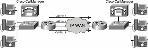
You can provision the network to carry a specific amount of real-time traffic. Any traffic that exceeds the provisioned bandwidth will subject all real-time traffic to delay, jitter, and possibly packet loss. The coder-decoder (codec) used for the call determines the bandwidth calculations used with call admission control.
Using Cisco CallManager, the following two types of call admission are possible:
- Locations-based call admission control The locations feature of Cisco CallManager provides a simplified call admission control scheme for centralized call-processing systems. A centralized system uses a single Cisco CallManager cluster to control all of the locations.
- Gatekeeper-based call admission control A gatekeeper device provides call admission control for distributed call-processing systems. In a distributed system, each site contains its own call-processing capability.
Locations-Based Call Admission Control
Cisco CallManager provides a simple locations-based call admission control mechanism for hub-and-spoke topologies, used primarily for centralized call processing.
The locations feature in Cisco CallManager lets you specify the maximum amount of audio bandwidth (for audio calls) and video bandwidth (for video calls) that is available for calls to and from each location. This specification limits the number of active calls and limits oversubscription of the priority bandwidth on the IP WAN links.
Note
Video calls are discussed in further detail in Chapter 28, "Introducing IP Video Telephony."
For the purpose of calculating bandwidth for call admission control, Cisco CallManager assumes that each call stream consumes the following amount of bandwidth:
- A G.711 call uses 80 kbps.
- A G.722 call uses 80 kbps.
- A G.723 call uses 24 kbps.
- A G.728 call uses 16 kbps.
- A G.729 call uses 24 kbps.
- A Global System for Mobile Communication (GSM) call uses 29 kbps.
- A wideband call uses 272 kbps.
Locations work in conjunction with regions to define the characteristics of a network link. Locations define the amount of available bandwidth for the link, and regions define the type of compression (G.711, G.723, or G.729) that is used on the link.
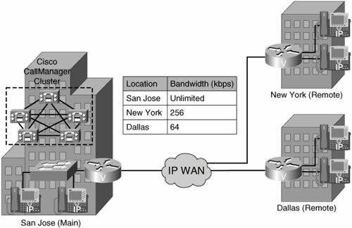
For example, in Figure 14-2, three locations are specified: San Jose (unlimited bandwidth), New York (256 kbps), and Dallas (64 kbps). Cisco CallManager continues to admit new calls to a link as long as sufficient bandwidth is still available. Thus, if the link to the New York location in this example has 256 kbps of available bandwidth, that link can support three G.711 calls at 80 kbps each and ten G.723 or G.729 calls at 24 kbps each. If any additional calls are received that would exceed the bandwidth limit, the system rejects them, the calling party receives a reorder tone, and a text message is displayed on the phone.
Figure 14-2. Location-Based Call Admission Control Example
Configuring Location-Based Call Admission Control
Configuring location-based call admission control in Cisco CallManager is a relatively simple process. Before you can accurately configure locations, you must ensure you have configured all the devices at remote locations to use a common codec when calling across the WAN. You can accomplish this through the region configuration assigned to the device pool of the remote phones. After you have accurately assigned the codec, follow these steps to configure locations in Cisco CallManager:
|
Step 1. |
Choose System > Location to configure a separate location for each IP WAN link to which you want to apply call admission control. As shown in Figure 14-3, allocate the maximum available bandwidth for calls across the link to that location. Figure 14-3. Configuring Locations 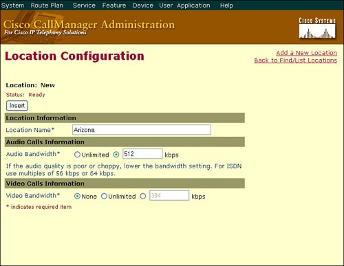
|
|
Step 2. |
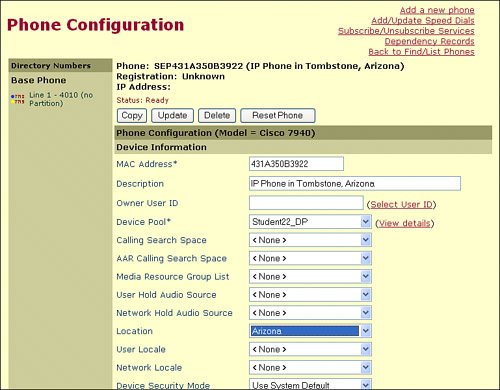
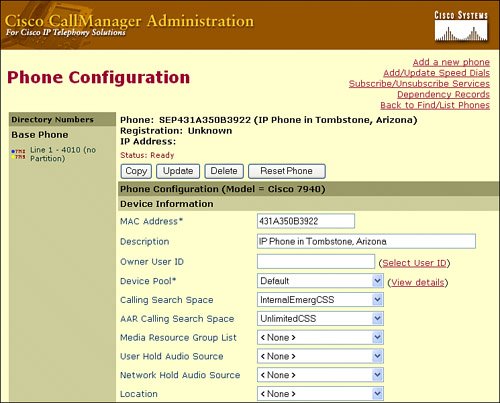
In the individual device configuration windows, configure the telephones and other devices and assign each of them to the appropriate device pool and location, as shown in Figure 14-4. |
Figure 14-4. Assigning Devices to a Location
AAR Overview
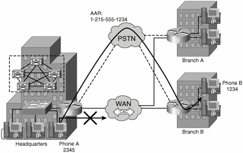
Automated Alternate Routing (AAR) is a mechanism used in conjunction with location-based call admission control. AAR allows calls to be rerouted through the PSTN by using an alternate number when Cisco CallManager blocks a call due to insufficient location bandwidth. With AAR, the caller does not need to hang up and redial the called party. If AAR is not configured, the user gets a reorder tone and the IP Phone displays "Not enough bandwidth."
AAR applies to centralized call-processing deployments. For instance, if a telephone in a company headquarters calls a telephone in branch B (shown in Figure 14-5) and the available bandwidth for the WAN link between the branches is insufficient (as computed by the locations mechanism), AAR can reroute the call through the PSTN using the following process:
- Phone A (DN = 2345) dials On-Net to phone B (DN = 1234).
- Call admission control denies the call.
- The external phone number mask 215-555-XXXX is added. The result is a fully qualified number, 215-555-1234.
Note
When working with the external phone number mask, it is important to keep straight which mask the CallManager will use when invoking AAR. When AAR redirects a call across the PSTN, it will always use the destination IP Phone's external phone number mask to transform the called number. The source IP Phone's external phone number mask will be used to transform the caller ID information.
- The prefix used to access the PSTN gateway is 9, and 1 is added to the string for numbering plan compatibility. These values are configured in the AAR group.
- 9-1-215-555-1234 is the new alternate dial string.
- The CallManager passes the new dial string through the route plan and sends the call across the PSTN.
Figure 14-5. AAR Scenario
AAR is transparent to users. It is configured so that users dial only the on-net (for example, four-digit) directory number (DN) of the called phone and no additional user input is required to reach the destination through the alternate network (such as the PSTN).
Keep the following requirements and caveats in mind when applying AAR:
- AAR requires call admission control based on locations and regions; AAR will function only if the WAN bandwidth is consumed.
- The IP Phone that originates a call should be in the same location as the gateway that routes the call to the PSTN.
- The called IP Phone and the gateway that terminates the call from the PSTN should be in the same location.
- If a call originates from a device in one location and terminates to a non-IP Phone in another location, AAR will not function. A voice-mail port on another vendor device also does not use AAR.
- If a call originates from a Cisco computer telephony integration (CTI) route point, AAR will not function.
- AAR does not work with SRST, which means that AAR will not function in the case of a WAN failure.
Configuring AAR
Configuring Cisco CallManager for AAR requires the following steps:
|
Step 1. |
Configure the locations. Use locations to implement call admission control in a centralized call-processing system. Cisco CallManager requires that the locations be arranged in a hub-and-spoke topology. |
|
Step 2. |
Configure the regions. Use regions to specify the type of compression and the amount of bandwidth used within a region and between regions. |
|
Step 3. |
Assign devices to a region and location. Use device pools to define sets of common characteristicsin this case, the region settingfor devices in a specific location. |
|
Step 4. |
Enable AAR clusterwide. Ensure that the Automated Alternate Routing Enable service parameter is set to True. |
|
Step 5. |
Configure AAR groups. For each AAR group, enter the prefix digits that are used for AAR within the AAR group, in addition to the prefix digits used for AAR between a given AAR group and other AAR groups. Devices such as gateways, telephones (by means of DNs), and trunks associate with AAR groups. |
|
Step 6. |
Configure the calling search space for AAR. Cisco CallManager uses the AAR calling search space to reroute calls when there is no available bandwidth on the WAN. |
|
Step 7. |
Configure the endpoints as follows:
|
Enabling AAR in the CallManager Cluster
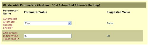
To access the settings for AAR throughout the cluster, open the Service > Service Parameters window for the Cisco CallManager service. You can use the Microsoft Internet Explorer Find feature to quickly locate the Automated Alternate Routing Enable service parameter, shown in Figure 14-6. Ensure this value is set to True. The default value for this service parameter is False.
Figure 14-6. Automated Alternate Routing Service Parameters
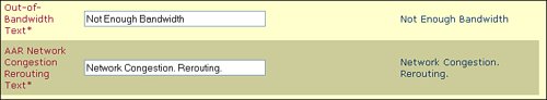
In addition, you can access the Service Parameters > CallManager > Clusterwide Parameters (DevicePhone) window (shown in Figure 14-7) to modify the two fields used to configure the messages that appear on the end user's IP Phone if there is no WAN bandwidth available or if AAR reroutes the call over the WAN.
Figure 14-7. Automated Alternate Routing End-User Notification Messages
AAR Group Configuration
If a user dials an internal number that goes to another location and the WAN is busy, the call should be rerouted over the PSTN. To place a call over the PSTN, Cisco CallManager needs the fully qualified number, not the internal DN, to reroute the call.
The destination number might require a prefix for an Off-Net access code (for example, 9) to be routed properly by the dial plan of the origination branch. Furthermore, if the point of origin is located in a different Numbering Plan Area (NPA, or area code), the network might require a prefix of 1 as part of the dialed string. Cisco CallManager uses the internal DN, the external phone number mask of the called DN, and the prefix to determine the alternate number for routing the call over the PSTN.
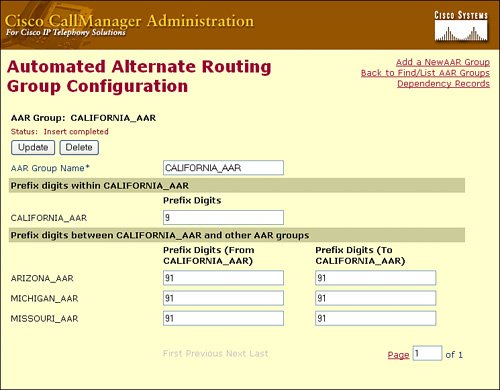
When configuring AAR, place the DNs in AAR groups. As shown in Figure 14-8, for each pair of AAR groups, you can configure prefix digits to add to the DNs for calls between the two groups, including prefix digits for calls originating and terminating within the same AAR group. For example, if a user in the California_AAR group dials a user in the Arizona_AAR group (shown in Figure 14-8) and the IP WAN connection bandwidth was oversubscribed, the CallManager would redirect the call over the PSTN connection, prefixing the digits "91" to the DN (which is also combined with the external phone number mask, discussed in the upcoming section).
Figure 14-8. Automated Alternate Routing Group Configuration Window
As a general rule, place DNs in the same AAR group if they share all of the following characteristics:
- A common off-net access code (for example, 9)
- A common PSTN dialing structure for interarea calls (for example, 1-NPA-Nxx-xxxx in North America)
- A common external phone number mask format
For example, assume that both the San Francisco and New York sites share all of the preceding characteristics. The DNs for San Francisco and New York can be placed into a single AAR group, and the group can be configured such that AAR calls placed within this AAR group are prefixed with 91. For phone A in San Francisco to reach phone B in New York (at 212-555-1212), the AAR group configuration prefixes 91 to the dialed string, yielding a completed string of 91-212-555-1212.
Complete these steps to add an AAR group:
|
Step 1. |
From the menu bar, choose Route Plan > AAR Group. |
|
Step 2. |
Click Add a New AAR Group. |
|
Step 3. |
Enter a name in the AAR Group Name field. |
|
Step 4. |
Click Continue. |
|
Step 5. |
In the Prefix Digits Within field for the group being added, enter the prefix digits to use for AAR within this AAR group. |
|
Step 6. |
In the Prefix Digits Between the group being added and Other AAR Groups area, complete the following fields:
|
|
Step 7. |
Click Insert to add this AAR group. |
Configuring Endpoints for AAR
Most of the setup process for AAR occurs when configuring the endpoints and gateways for AAR. This process can be completed in three steps:
|
Step 1. |
Configure the DN to use the AAR group, as shown in Figure 14-9. An AAR group setting of None specifies that no rerouting of blocked calls will be attempted. Figure 14-9. Configuring DNs for AAR Groups 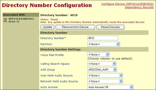
|
|
Step 2. |
Assign the external phone number mask to the DN. Figure 14-10. Configuring DNs for AAR Groups 
Indicate the phone number (or mask) that is used to send caller ID information when a call is placed from this line. A maximum of 30 numeric and X characters can be added. The Xs represent the DN and must appear at the end of the pattern. For example, if you specify a mask of 972813XXXX, an external call from extension 1234 displays a caller ID number of 9728131234. |
Tip
Remember, the external phone number mask should always be the number the DN you are configuring through the PSTN. If your organization does not use Direct Inward Dial (DID) ranges, you should configure the external phone number mask as the location's general number, allowing a receptionist to redirect the call to the internal extension.
|
Step 3. |
Configure the phone (or gateway) to use the AAR calling search space. |
Figure 14-11. Configuring AAR Calling Search Space
Gatekeeper-Based Call Admission Control
Gatekeeper call admission control reduces configuration overhead by eliminating the need to configure separate individual intercluster trunks between clusters. A gatekeeper can determine the IP addresses of devices that are registered with it, or you can enter the IP addresses explicitly. It uses these IP addresses to refer calls between endpoints (an endpoint could be an entire Cisco CallManager cluster). For example, a call could originate from one CallManager cluster where the route plan indicates to forward the call to the gatekeeper. The gatekeeper responds with the real IP address of the CallManager in another cluster that manages the extension the call is attempting to reach.
If you choose the gatekeeper method of call admission control, you will need to set up an Intercluster Trunk (gatekeeper-controlled) or H.225 trunk (gatekeeper-controlled). These trunks are configured to point to the gatekeeper device and are included in the dial plan for your network.
When you configure gatekeeper-controlled trunks, Cisco CallManager automatically creates a virtual trunk device. The IP address of this device changes dynamically to reflect the IP address of the remote device as determined by the gatekeeper. For example, if the gatekeeper forwards the call to another CallManager cluster, the endpoint IP address for the virtual trunk device points to the CallManager server in the remote cluster.
Note
Much of the H.323 gatekeeper configuration is covered in Cisco Voice Gateways and Gatekeepers (ISBN: 1-58705-258-x) from Cisco Press. The gatekeeper configuration discussed in this book is directly related to the Cisco CallManager integration.
Gatekeeper Communication
For a Cisco CallManager to use an H.323 gatekeeper, a new communication exchange occurs between the gatekeeper and the Cisco CallManager. The first process that an endpoint must go through is gatekeeper discovery. An endpoint achieves gatekeeper discovery either manually or through autodiscovery.
Autodiscovery uses multicast to discover the gatekeeper. A gatekeeper request (GRQ) is multicast, and any gatekeeper that can accept a registration returns a gatekeeper confirmation (GCF). If a gatekeeper cannot accept a registration, it returns a gatekeeper reject (GRJ). This exchange is illustrated in Figure 14-12.
Figure 14-12. Gatekeeper Discovery

Note
Although the exchange shown in Figure 14-12 is supported on most H.323 endpoints and gateways (as it is defined in the H.323 standard), Cisco CallManager does not support gatekeeper discovery messages. Because the gatekeeper can play such an integral role in the CallManager route plan, H.323 gatekeepers must be manually configured rather than dynamically discovered.
After the discovery process has completed, the Cisco CallManager must register with the gatekeeper. A Cisco IOS gatekeeper supports two types of registration:
- Full registration
- Lightweight registration
An endpoint must always use a full registration during the initial registration process. An endpoint can use lightweight registration to maintain registration. Should an endpoint become unregistered with the gatekeeper, a full registration is required.
Full registration requires the endpoint to register any E.164 address, H.323 identifier, device type, and other possible parameters each time that it registers. This procedure involves additional processing load on a gatekeeper every time an endpoint registers or renews its registration. The registration request (RRQ) includes the time between renewal of registrations or Time to Live (TTL), and the gatekeeper can replace this value or return this value unchanged.
Note
You can make the returned TTL value configurable with Cisco IOS Software Release 12.1.5T and later.
The lower the TTL value, the higher the load on the gatekeeper processing the registration. The impact of a higher value is that it takes longer for the gatekeeper to become aware that an endpoint has lost connectivity. Use 30 to 300 seconds, depending on design requirements.
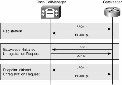
When the endpoint sends a full RRQ to the gatekeeper, the gatekeeper responds with a registration confirmation (RCF) to accept or a registration rejection (RRJ) to refuse, as illustrated in Figure 14-13. The gatekeeper can refuse the registration for many reasons, such as duplicate E.164 or H323 identifiers or ambiguous information.
Figure 14-13. Gatekeeper Registration and Unregistration
An endpoint registration has a finite life. Before the TTL expires, the endpoint is required to renew its registration by sending an RRQ. If the TTL expires and the gatekeeper has not received an RRQ from the endpoint, the endpoint becomes unregistered.
Lightweight registration reduces the processing load on the gatekeeper during registration renewal. The gatekeeper receives an RRQ with the keepalive bit set and the minimum required information from the endpoint. If the gatekeeper accepts the renewal, the gatekeeper returns an RCF to the endpoint and resets the TTL timer. If the gatekeeper rejects the renewal with an RRJ, the endpoint becomes unregistered.
If the endpoint is unregistered, the endpoint must start the gatekeeper discovery and registration process again.
At any time, an endpoint or a gatekeeper can cancel a registration with an unregister request (URQ), normally used during configuration changes.
An endpoint or gatekeeper sends an unregister confirmation (UCF) in response to a URQ. If an unregistered endpoint sends a URQ to a gatekeeper, the gatekeeper responds with an unregister reject (URJ) to indicate the error. Cisco IOS gatekeepers, Cisco IOS gateways, and Cisco CallManager support lightweight registration.
After the Cisco CallManagers from multiple clusters register with the gatekeeper, the gatekeeper device can perform admission and bandwidth control between the clusters. Telephony endpoints (Cisco IP Phones or Cisco IP SoftPhones) send an admission request (ARQ) to the gatekeeper to initiate a call, as shown in Figure 14-14. The ARQ contains an H.323 identifier or the E.164 address of a destination or called party that it wants to reach. Also contained within the ARQ message are the call bandwidth (not including the header overhead), the source E.164 address, and the H.323 identifier of the calling party.
Figure 14-14. Gatekeeper Admission Control
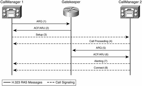
The gatekeeper will respond to the ARQ with either an admission confirmation (ACF) or an admission reject (ARJ). The gatekeeper sends the ACF if the requested bandwidth is available and the called endpoint is found. The ACF contains the IP address of the endpoint. On receipt of an ACF from the gatekeeper, the endpoint sends a setup message directly to the other endpoint, using the IP address returned in the ACF. If bandwidth is unavailable or if the called endpoint is not registered, the gatekeeper sends an ARJ.
When an endpoint terminates a call, the endpoint is required to indicate the termination to the gatekeeper and return the used bandwidth. The endpoint sends a disengage request (DRQ) to the gatekeeper to indicate that the call is complete. The gatekeeper responds with a disengage confirmation (DCF) and returns the previously used bandwidth to the pool.
The gatekeeper can also clear the call by sending a DRQ to the endpoint, forcing the endpoint to clear the call with the other endpoint and return a DCF.
If during the duration of the call the bandwidth requirement changes, because of a changing codec or additional media channels opening or closing, the endpoint can request or release the bandwidth by sending a bandwidth request (BRQ). The gatekeeper responds with a bandwidth confirmation (BCF) if the bandwidth is available or with a bandwidth reject (BRJ) if the bandwidth is not available, as shown in Figure 14-15.
Figure 14-15. Gatekeeper Disengage Bandwidth Control

Gatekeeper-Based Call Admission Control Configuration
The general recommendation is to use separate Cisco routers as dedicated gatekeepers in your network in a number appropriate for your topology. Cisco also supports clustering the gatekeeper routers using H.323 clustering with the Gatekeeper Update Protocol (GUP). You can configure a gatekeeper with the appropriate Cisco IOS feature set, such as the Enterprise Plus/H323 MCM feature set.
Tip
Other feature sets of the IOS have begun adding gatekeeper support. The best way to find out what feature set you should download is to use the Cisco feature navigator utility available at http://www.cisco.com/go/fn.
The following are the four general steps for configuring call admission control using gatekeepers and trunks:
|
Step 1. |
On the gatekeeper device, configure the appropriate zones and bandwidth allocations for the various Cisco CallManager nodes that will route calls to it. Example 14-1. Sample H.323 Gatekeeper Basic Configuration
|
|||||||||||||||
|
Step 2. |
Configure gatekeeper settings in Cisco CallManager Administration. Make sure that the hostname or IP address is set the same way on each Cisco CallManager. You can register multiple gatekeepers per Cisco CallManager cluster. Figure 14-16. Configuring a Gatekeeper Reference in Cisco CallManager 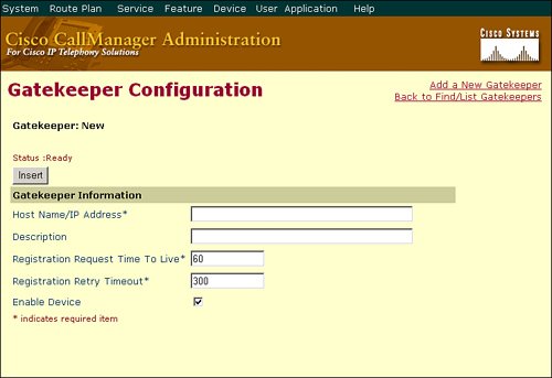
|
|||||||||||||||
|
Step 3. |
Configure the appropriate intercluster trunks or H.225 trunks to specify gatekeeper information. The H.225 trunk allows connectivity to H.323 Cisco IOS gateways. The intercluster trunk provides specific Cisco functionality for calls between Cisco CallManager clusters.
|
You can add gatekeeper-controlled H.225 and intercluster trunks to the Cisco CallManager configuration using the same process as adding nongatekeeper controlled trunks, which was discussed in Chapter 10, "Cisco Unified CallManager Route Plan Basics." The trunk should point to the gatekeeper device rather than the remote cluster and be configured for the appropriate default technology prefix and local zone name that you have configured on the gatekeeper device, as shown in Figure 14-17.
Figure 14-17. Configuring a Gatekeeper-Controlled Trunk

Note
The two different types of gatekeeper-controlled trunks have caused much confusion with CallManager administrators. The Intercluster Trunk is a Cisco proprietary trunking method that allowed communication between Cisco CallManager clusters. This type of trunk is only necessary when communicating with clusters running Cisco CallManager 3.2 or earlier. The H.225 trunk is an industry standard trunking method used to communicate with any type of H.323-compliant device, including CallManager clusters since version 3.3 and Cisco CallManager Express platforms.
|
Step 4. |
Configure a route pattern to route calls to each gatekeeper-controlled trunk. |
Survivable Remote Site Telephony |
Part I: Cisco CallManager Fundamentals
Introduction to Cisco Unified Communications and Cisco Unified CallManager
Cisco Unified CallManager Clustering and Deployment Options
- Cisco Unified CallManager Clustering and Deployment Options
- The Two Sides of the Cisco Unified CallManager Cluster
- Cluster Redundancy Designs
- Call-Processing Deployment Models
- Summary
- Review Questions
Cisco Unified CallManager Installation and Upgrades
- Cisco Unified CallManager Installation and Upgrades
- Cisco Unified CallManager 4.x Clean Installation Process
- Upgrading Prior Cisco Unified CallManager Versions
- Summary
- Review Questions
Part II: IPT Devices and Users
Cisco IP Phones and Other User Devices
Configuring Cisco Unified CallManager to Support IP Phones
- Configuring Cisco Unified CallManager to Support IP Phones
- Configuring Intracluster IP Phone Communication
- IP Phone Configuration
- Case Study: Device Pool Design
- Summary
- Review Questions
Cisco IP Telephony Users
- Cisco IP Telephony Users
- Cisco CallManager User Database
- Cisco CallManager User Configuration
- User Logon and Device Configuration
- Summary
- Review Questions
Cisco Bulk Administration Tool
- Cisco Bulk Administration Tool
- The Cisco Bulk Administration Tool
- Using the Tool for Auto-Registered Phone Support
- Summary
- Review Questions
Part III: IPT Network Integration and Route Plan
Cisco Catalyst Switches
- Cisco Catalyst Switches
- Catalyst Switch Role in IP Telephony
- Powering the Cisco IP Phone
- Data and Voice VLANs
- Configuring Class of Service
- Summary
- Review Questions
Configuring Cisco Gateways and Trunks
- Configuring Cisco Gateways and Trunks
- Cisco Gateway Concepts
- Configuring Access Gateways
- Cisco Trunk Concepts
- Configuring Intercluster Trunks
- SIP and Cisco CallManager
- Summary
- Review Questions
Cisco Unified CallManager Route Plan Basics
- Cisco Unified CallManager Route Plan Basics
- External Call Routing
- Route Plan Configuration Process
- Summary
- Review Questions
Cisco Unified CallManager Advanced Route Plans
- Cisco Unified CallManager Advanced Route Plans
- Route Filters
- Discard Digit Instructions
- Transformation Masks
- Translation Patterns
- Route Plan Report
- Summary
- Review Questions
Configuring Hunt Groups and Call Coverage
- Configuring Hunt Groups and Call Coverage
- Call Distribution Components
- Configuring Line Groups, Hunt Lists, and Hunt Pilots
- Summary
- Review Questions
Implementing Telephony Call Restrictions and Control
- Implementing Telephony Call Restrictions and Control
- Class of Service Overview
- Partitions and Calling Search Spaces Overview
- Time-of-Day Routing Overview
- Configuring Time-of-Day Routing
- Time-of-Day Routing Usage Scenario
- Summary
- Review Questions
Implementing Multiple-Site Deployments
- Implementing Multiple-Site Deployments
- Call Admission Control
- Survivable Remote Site Telephony
- Summary
- Review Questions
Part IV: VoIP Features
Media Resources
- Media Resources
- Introduction to Media Resources
- Conference Bridge Resources
- Media Termination Point Resources
- Annunciator Resources
- Transcoder Resources
- Music on Hold Resources
- Media Resource Management
- Summary
- Review Questions
Configuring User Features, Part 1
- Configuring User Features, Part 1
- Basic IP Phone Features
- Softkey Templates
- Enhanced IP Phone Features
- Barge and Privacy
- IP Phone Services
- Summary
- Review Questions
Configuring User Features, Part 2
- Configuring User Features, Part 2
- Cisco CallManager Extension Mobility
- Client Matter Codes and Forced Authentication Codes
- Call Display Restrictions
- Malicious Call Identification
- Multilevel Precedence and Preemption
- Summary
- Review Questions
Configuring Cisco Unified CallManager Attendant Console
- Configuring Cisco Unified CallManager Attendant Console
- Introduction to Cisco CallManager Attendant Console
- Call Routing and Call Queuing
- Server and Administration Configuration
- Cisco Attendant Console Features
- Summary
- Review Questions
Configuring Cisco IP Manager Assistant
- Configuring Cisco IP Manager Assistant
- Cisco IP Manager Assistant Overview
- Cisco IP Manager Assistant Architecture
- Configuring Cisco IPMA for Shared-Line Support
- Summary
- Review Questions
Part V: IPT Security
Securing the Windows Operating System
- Securing the Windows Operating System
- Threats Targeting the Operating System
- Security and Hot Fix Policy
- Operating System Hardening
- Antivirus Protection
- Cisco Security Agent
- Administrator Password Policy
- Common Windows Exploits
- Security Taboos
- Summary
- Review Questions
Securing Cisco Unified CallManager Administration
- Securing Cisco Unified CallManager Administration
- Threats Targeting Remote Administration
- Securing CallManager Communications Using HTTPS
- Multilevel Administration
- Summary
- Review Questions
Preventing Toll Fraud
- Preventing Toll Fraud
- Toll Fraud Exploits
- Preventing Call Forward and Voice-Mail Toll Fraud Using Calling Search Spaces
- Blocking Commonly Exploited Area Codes
- Using Time-of-Day Routing
- Using FAC and CMC
- Restricting External Transfers
- Dropping Conference Calls
- Summary
- Review Questions
Hardening the IP Phone
Understanding Cryptographic Fundamentals
- Understanding Cryptographic Fundamentals
- What Is Cryptography?
- Symmetric Encryption
- Asymmetric Encryption
- Hash Functions
- Digital Signatures
- Summary
- Review Questions
Understanding the Public Key Infrastructure
- Understanding the Public Key Infrastructure
- The Need for a PKI
- PKI as a Trusted Third-Party Protocol
- PKI Entities
- PKI Enrollment
- PKI Revocation and Key Storage
- PKI Example
- Summary
- Review Questions
Understanding Cisco IP Telephony Authentication and Encryption Fundamentals
- Understanding Cisco IP Telephony Authentication and Encryption Fundamentals
- Threats Targeting the IP Telephony System
- How CallManager Protects Against Threats
- PKI Topologies in Cisco IP Telephony
- PKI Enrollment in Cisco IP Telephony
- Keys and Certificate Storage in Cisco IP Telephony
- Authentication and Integrity
- Encryption
- Summary
- Review Questions
Configuring Cisco IP Telephony Authentication and Encryption
- Configuring Cisco IP Telephony Authentication and Encryption
- Authentication and Encryption Configuration Overview
- Enabling Services Required for Security
- Using the CTL Client
- Working with Locally Significant Certificates
- Configuring the Device Security Mode
- Negotiating Device Security Mode
- Generating a CAPF Report
- Summary
- Review Questions
Part VI: IP Video
Introducing IP Video Telephony
- Introducing IP Video Telephony
- IP Video Telephony Solution Components
- Video Call Concepts
- Video Protocols Supported in Cisco CallManager
- Bandwidth Management
- Call Admission Control Within a Cluster
- Call Admission Control Between Clusters
- Summary
- Review Questions
Configuring Cisco VT Advantage
- Configuring Cisco VT Advantage
- Cisco VT Advantage Overview
- How Calls Work with Cisco VT Advantage
- Configuring Cisco CallManager for Video
- Configuring Cisco IP Phones for Cisco VT Advantage
- Installing Cisco VT Advantage on a Client
- Summary
- Review Questions
Part VII: IPT Management
Introducing Database Tools and Cisco Unified CallManager Serviceability
- Introducing Database Tools and Cisco Unified CallManager Serviceability
- Database Management Tools
- Cisco CallManager Serviceability Overview
- Tools Overview
- Summary
- Review Questions
Monitoring Performance
- Monitoring Performance
- Performance Counters
- Microsoft Event Viewer
- Microsoft Performance Monitor
- Real-Time Monitoring Tool Overview
- Summary
- Review Questions
Configuring Alarms and Traces
- Configuring Alarms and Traces
- Alarm Overview
- Alarm Configuration
- Trace Configuration
- Trace Analysis
- Trace Collection
- Bulk Trace Analysis
- Additional Trace Tools
- Summary
- Review Questions
Configuring CAR
- Configuring CAR
- CAR Overview
- CAR Configuration
- Report Scheduling
- System Database Configuration
- User Report Configuration
- Summary
- Review Questions
Using Additional Management and Monitoring Tools
- Using Additional Management and Monitoring Tools
- Remote Management Tools
- Dependency Records
- Password Changer Tool
- Cisco Dialed Number Analyzer
- Quality Report Tool
- Summary
- Review Questions
Part VIII: Appendix
Appendix A. Answers to Review Questions
Index
EAN: 2147483647
Pages: 329
