Call Admission Control Within a Cluster
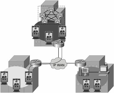
Why do you need to configure call admission control for video calls? The answer to this question is quite simple. If you do not control the number of video and voice calls over your WAN links in a centralized deployment (shown in Figure 28-5), periodically you will see decreased video and voice throughout the whole system. With call admission control, you control the number of calls on the WAN link and ensure that all calls, video and audio-only, are processed throughout the network with acceptable quality.
Figure 28-5. Typical Centralized Call Control Environment
Cisco CallManager uses regions and locations to implement call admission control:
- Regions define the codec used and maximum video bandwidth allowed per call. This value is configurable for calls within each region and for calls between any pair of regions.
- Locations define the maximum bandwidth allowed for all calls to and from a location.
In Cisco CallManager, devices derive their region setting with the associated device pool configuration. You can assign locations on a per-device basis. If you assign locations at the device level, it overrides the setting inherited from the device pool.
Calls between devices at the same location do not need call admission control because the assumption is that these devices reside on the same LAN that has "unlimited" available bandwidth. However, for calls between devices at different locations, the assumption is that there is an IP WAN link in between that has limited available bandwidth.
Region Configuration
When you are configuring a region, you set two fields in Cisco CallManager Administration: the Audio Codec and the Video Call Bandwidth fields, as shown in Figure 28-6. Note that the audio setting specifies a codec type, whereas the video setting specifies the bandwidth that you want to allow. However, even though the notation is different, the Audio Codec and Video Call Bandwidth fields actually perform similar functions. The Audio Codec value defines the maximum bit rate allowed for audio-only calls and for the audio channel in video calls.
Figure 28-6. Cisco CallManager Region Configuration
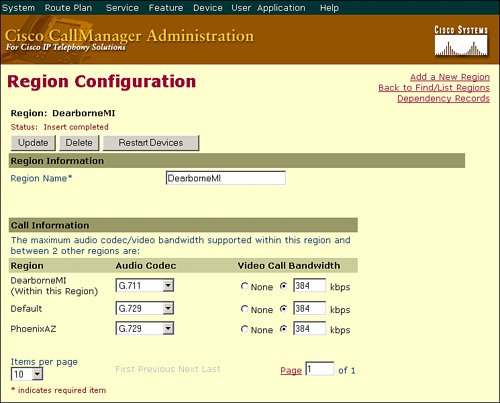
For instance, if you set the Audio Codec value for a region to G.711, Cisco CallManager allocates 64 kbps as the maximum bandwidth allowed for the audio channel for that region. In this case, Cisco CallManager permits calls using G.711, G.728, or G.729. However, if you set the Audio Codec value to G.729, Cisco CallManager allocates only 8 kbps as the maximum bandwidth allowed for the audio channel; in addition, Cisco CallManager permits calls using only G.729, because G.711, G.722, and G.728 all require more than 8 kbps.
The Video Call Bandwidth value defines the maximum bit rate for the video call, that is, the bit rate of the voice and video channels. For instance, if you want to allow video calls at a speed of 384 kbps using G.711 audio, you would set the Video Call Bandwidth value to 384 kbps and the Audio Codec value to G.711. The bit rate that would be used by the video channel thus would be 320 kbps. If the Video Call Bandwidth value is set to None for the region, Cisco CallManager either terminates the call or allows the call to pass as an audio-only call, depending on whether the calling device has the Retry Video Call as Audio option enabled.
In summary, the Audio Codec field defines the maximum bit rate used for the audio channel of audio-only calls and for the audio channel of video calls, whereas the Video Call Bandwidth field defines the maximum bit rate allowed for video calls and includes the audio portion of the video call.
Note
Video endpoints typically support only G.711 and G.722, whereas audio-only endpoints typically support only G.711 and G.729. Because you cannot configure the audio codec for audio and video calls separately, often the only common audio codec for mixed environments (including third-party equipment) is G.711.
Location Configuration
When configuring locations, you also set two fields in Cisco CallManager Administration: the Audio Bandwidth and the Video Bandwidth values, shown in Figure 28-7. Unlike regions, however, audio bandwidth for locations applies only to audio-only calls, whereas video bandwidth again applies to the video call (that is, audio and video channels).
Figure 28-7. Cisco CallManager Location Configuration
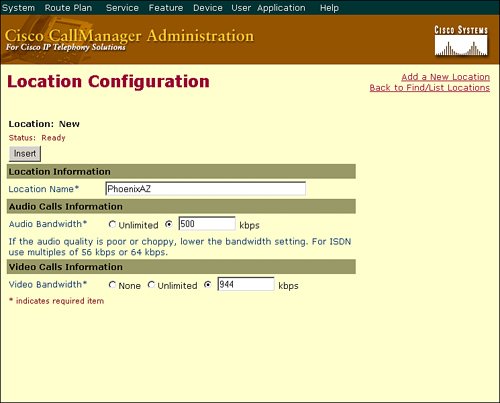
The audio and video bandwidth are kept separate because if both types of calls shared a single allocation of bandwidth, it is very likely that audio calls would take all of the available bandwidth and leave no room for any video calls, or vice versa.
Both the Audio Bandwidth and the Video Bandwidth fields offer three options: None, Unlimited, or a field that accepts numeric values. However, the values entered in these fields use two different calculation models:
- For the Audio Bandwidth field, the value entered has to include the Layer 3 and 4 overhead required for the call. For instance, if you want to permit a single G.729 call to or from a location, you would enter the value 24 kbps. For a G.711 call, you would enter the value 80 kbps. The payload of a G.711 voice call is 64 kbps; the 80-kbps value is the 64-kbps payload plus 16-kbps RPT plus UDP.
- The value in the Video Bandwidth field, by contrast, is entered without any overhead. For instance, for a 128-kbps call, enter the value 128 kbps; for a 384-kbps call, enter the value 384 kbps. As with the values used in the Video Bandwidth field for regions, it is recommended that you always use increments of 56 kbps or 64 kbps for the Video Bandwidth field for locations.
Note
The value None in the Video Bandwidth field indicates that video calls are not allowed between this location and other locations. Video calls can, however, be placed within this location.
Call Admission Control Example
Figure 28-8 illustrates an example of audio and video bandwidth requirements for a company with a three-site network. The San Francisco location has a 1.544-Mbps T1 circuit connecting it to the San Jose main campus. The system administrator wants to allow four G.729 voice calls and one 384-kbps video call to or from that location.
Figure 28-8. Video Call Bandwidth Example
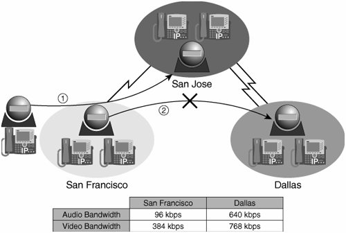
The Dallas location has two 1.544-Mbps T1 circuits connecting it to the San Jose main campus, and the administrator wants to allow eight G.711 voice calls and two 384-kbps video calls to or from that location.
For this example, the administrator might set the San Francisco and Dallas locations to the values in Table 28-5.
|
Location |
Number of Audio Calls Desired |
Audio Bandwidth Field Value |
Number of Video Calls Desired |
Video Bandwidth Field Value |
|---|---|---|---|---|
|
San Francisco |
Four using G.729 |
96 kbps (4 * 24 kbps) |
One at 384 kbps |
384 kbps |
|
Dallas |
Eight using G.711 |
640 kbps (8 * 80 kbps) |
Two at 384 kbps |
768 kbps |
First, a video device in San Francisco calls a video device in San Jose. Call admission control allows exactly one 384-kbps video call between San Francisco and any other location. The video call is active.
Next, another video device from San Francisco tries to set up a video call to a video device in Dallas. Call admission control does not allow a second video call from San Francisco to any other location and denies the video call.
If the call fails because of insufficient location bandwidth, it will not be retried with lower-bit-rate codecs. In this scenario, with no further configuration of the Cisco CallManager, the call (both audio and video portions) will be rejected.
Retry Video Call as Audio
The Retry Video Call as Audio setting appears as a check box in the IP Phone configuration in Cisco CallManager Administration, as shown in Figure 28-9.
Figure 28-9. Configuring the Retry Video Call as Audio Setting
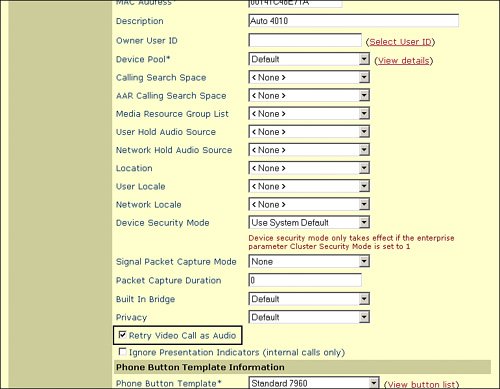
This setting is enabled by default on all device types and applies to these scenarios only:
- The region is configured not to allow video.
- The location is configured not to allow video, or the requested video speed exceeds the available video bandwidth for that location.
- The requested video speed exceeds the zone bandwidth limits of the gatekeeper.
When this option is activated (checked), if there is not enough bandwidth for a video call (for example, if the Cisco CallManager regions or locations do not allow video for that call), Cisco CallManager will retry the call as an audio-only call. When this option is deactivated (unchecked), Cisco CallManager will not retry the video call as audio only but will instead either reject the call or reroute the video call by whatever Automated Alternate Routing (AAR) path is configured.
The Retry Video Call as Audio option takes effect only on the terminating (called) device, allowing flexibility for the calling device to have different options (retry or AAR) for different destinations.
Note
The called device determines the result. In other words, when one device calls another and any of the discussed insufficient bandwidth conditions applies, Cisco CallManager looks at the destination device to see whether the Retry Video Call as Audio option is enabled.
Part I: Cisco CallManager Fundamentals
Introduction to Cisco Unified Communications and Cisco Unified CallManager
Cisco Unified CallManager Clustering and Deployment Options
- Cisco Unified CallManager Clustering and Deployment Options
- The Two Sides of the Cisco Unified CallManager Cluster
- Cluster Redundancy Designs
- Call-Processing Deployment Models
- Summary
- Review Questions
Cisco Unified CallManager Installation and Upgrades
- Cisco Unified CallManager Installation and Upgrades
- Cisco Unified CallManager 4.x Clean Installation Process
- Upgrading Prior Cisco Unified CallManager Versions
- Summary
- Review Questions
Part II: IPT Devices and Users
Cisco IP Phones and Other User Devices
Configuring Cisco Unified CallManager to Support IP Phones
- Configuring Cisco Unified CallManager to Support IP Phones
- Configuring Intracluster IP Phone Communication
- IP Phone Configuration
- Case Study: Device Pool Design
- Summary
- Review Questions
Cisco IP Telephony Users
- Cisco IP Telephony Users
- Cisco CallManager User Database
- Cisco CallManager User Configuration
- User Logon and Device Configuration
- Summary
- Review Questions
Cisco Bulk Administration Tool
- Cisco Bulk Administration Tool
- The Cisco Bulk Administration Tool
- Using the Tool for Auto-Registered Phone Support
- Summary
- Review Questions
Part III: IPT Network Integration and Route Plan
Cisco Catalyst Switches
- Cisco Catalyst Switches
- Catalyst Switch Role in IP Telephony
- Powering the Cisco IP Phone
- Data and Voice VLANs
- Configuring Class of Service
- Summary
- Review Questions
Configuring Cisco Gateways and Trunks
- Configuring Cisco Gateways and Trunks
- Cisco Gateway Concepts
- Configuring Access Gateways
- Cisco Trunk Concepts
- Configuring Intercluster Trunks
- SIP and Cisco CallManager
- Summary
- Review Questions
Cisco Unified CallManager Route Plan Basics
- Cisco Unified CallManager Route Plan Basics
- External Call Routing
- Route Plan Configuration Process
- Summary
- Review Questions
Cisco Unified CallManager Advanced Route Plans
- Cisco Unified CallManager Advanced Route Plans
- Route Filters
- Discard Digit Instructions
- Transformation Masks
- Translation Patterns
- Route Plan Report
- Summary
- Review Questions
Configuring Hunt Groups and Call Coverage
- Configuring Hunt Groups and Call Coverage
- Call Distribution Components
- Configuring Line Groups, Hunt Lists, and Hunt Pilots
- Summary
- Review Questions
Implementing Telephony Call Restrictions and Control
- Implementing Telephony Call Restrictions and Control
- Class of Service Overview
- Partitions and Calling Search Spaces Overview
- Time-of-Day Routing Overview
- Configuring Time-of-Day Routing
- Time-of-Day Routing Usage Scenario
- Summary
- Review Questions
Implementing Multiple-Site Deployments
- Implementing Multiple-Site Deployments
- Call Admission Control
- Survivable Remote Site Telephony
- Summary
- Review Questions
Part IV: VoIP Features
Media Resources
- Media Resources
- Introduction to Media Resources
- Conference Bridge Resources
- Media Termination Point Resources
- Annunciator Resources
- Transcoder Resources
- Music on Hold Resources
- Media Resource Management
- Summary
- Review Questions
Configuring User Features, Part 1
- Configuring User Features, Part 1
- Basic IP Phone Features
- Softkey Templates
- Enhanced IP Phone Features
- Barge and Privacy
- IP Phone Services
- Summary
- Review Questions
Configuring User Features, Part 2
- Configuring User Features, Part 2
- Cisco CallManager Extension Mobility
- Client Matter Codes and Forced Authentication Codes
- Call Display Restrictions
- Malicious Call Identification
- Multilevel Precedence and Preemption
- Summary
- Review Questions
Configuring Cisco Unified CallManager Attendant Console
- Configuring Cisco Unified CallManager Attendant Console
- Introduction to Cisco CallManager Attendant Console
- Call Routing and Call Queuing
- Server and Administration Configuration
- Cisco Attendant Console Features
- Summary
- Review Questions
Configuring Cisco IP Manager Assistant
- Configuring Cisco IP Manager Assistant
- Cisco IP Manager Assistant Overview
- Cisco IP Manager Assistant Architecture
- Configuring Cisco IPMA for Shared-Line Support
- Summary
- Review Questions
Part V: IPT Security
Securing the Windows Operating System
- Securing the Windows Operating System
- Threats Targeting the Operating System
- Security and Hot Fix Policy
- Operating System Hardening
- Antivirus Protection
- Cisco Security Agent
- Administrator Password Policy
- Common Windows Exploits
- Security Taboos
- Summary
- Review Questions
Securing Cisco Unified CallManager Administration
- Securing Cisco Unified CallManager Administration
- Threats Targeting Remote Administration
- Securing CallManager Communications Using HTTPS
- Multilevel Administration
- Summary
- Review Questions
Preventing Toll Fraud
- Preventing Toll Fraud
- Toll Fraud Exploits
- Preventing Call Forward and Voice-Mail Toll Fraud Using Calling Search Spaces
- Blocking Commonly Exploited Area Codes
- Using Time-of-Day Routing
- Using FAC and CMC
- Restricting External Transfers
- Dropping Conference Calls
- Summary
- Review Questions
Hardening the IP Phone
Understanding Cryptographic Fundamentals
- Understanding Cryptographic Fundamentals
- What Is Cryptography?
- Symmetric Encryption
- Asymmetric Encryption
- Hash Functions
- Digital Signatures
- Summary
- Review Questions
Understanding the Public Key Infrastructure
- Understanding the Public Key Infrastructure
- The Need for a PKI
- PKI as a Trusted Third-Party Protocol
- PKI Entities
- PKI Enrollment
- PKI Revocation and Key Storage
- PKI Example
- Summary
- Review Questions
Understanding Cisco IP Telephony Authentication and Encryption Fundamentals
- Understanding Cisco IP Telephony Authentication and Encryption Fundamentals
- Threats Targeting the IP Telephony System
- How CallManager Protects Against Threats
- PKI Topologies in Cisco IP Telephony
- PKI Enrollment in Cisco IP Telephony
- Keys and Certificate Storage in Cisco IP Telephony
- Authentication and Integrity
- Encryption
- Summary
- Review Questions
Configuring Cisco IP Telephony Authentication and Encryption
- Configuring Cisco IP Telephony Authentication and Encryption
- Authentication and Encryption Configuration Overview
- Enabling Services Required for Security
- Using the CTL Client
- Working with Locally Significant Certificates
- Configuring the Device Security Mode
- Negotiating Device Security Mode
- Generating a CAPF Report
- Summary
- Review Questions
Part VI: IP Video
Introducing IP Video Telephony
- Introducing IP Video Telephony
- IP Video Telephony Solution Components
- Video Call Concepts
- Video Protocols Supported in Cisco CallManager
- Bandwidth Management
- Call Admission Control Within a Cluster
- Call Admission Control Between Clusters
- Summary
- Review Questions
Configuring Cisco VT Advantage
- Configuring Cisco VT Advantage
- Cisco VT Advantage Overview
- How Calls Work with Cisco VT Advantage
- Configuring Cisco CallManager for Video
- Configuring Cisco IP Phones for Cisco VT Advantage
- Installing Cisco VT Advantage on a Client
- Summary
- Review Questions
Part VII: IPT Management
Introducing Database Tools and Cisco Unified CallManager Serviceability
- Introducing Database Tools and Cisco Unified CallManager Serviceability
- Database Management Tools
- Cisco CallManager Serviceability Overview
- Tools Overview
- Summary
- Review Questions
Monitoring Performance
- Monitoring Performance
- Performance Counters
- Microsoft Event Viewer
- Microsoft Performance Monitor
- Real-Time Monitoring Tool Overview
- Summary
- Review Questions
Configuring Alarms and Traces
- Configuring Alarms and Traces
- Alarm Overview
- Alarm Configuration
- Trace Configuration
- Trace Analysis
- Trace Collection
- Bulk Trace Analysis
- Additional Trace Tools
- Summary
- Review Questions
Configuring CAR
- Configuring CAR
- CAR Overview
- CAR Configuration
- Report Scheduling
- System Database Configuration
- User Report Configuration
- Summary
- Review Questions
Using Additional Management and Monitoring Tools
- Using Additional Management and Monitoring Tools
- Remote Management Tools
- Dependency Records
- Password Changer Tool
- Cisco Dialed Number Analyzer
- Quality Report Tool
- Summary
- Review Questions
Part VIII: Appendix
Appendix A. Answers to Review Questions
Index
EAN: 2147483647
Pages: 329
