Route Filters
When creating route patterns, you can use the "@" wildcard to represent all the routes defined in the North American Numbering Plan (NANP). Although this is a simple way to provide PSTN access to your internal users, you might be providing far more access than you intend. As shown in Figure 11-1, the NANP includes high-expense patterns such as international dialing access, service numbers (such as 411), and 900 numbers. You can assign route filters to route patterns with the @ route pattern to help reduce the danger that full access to the NANP provides. You can accomplish this reduction by filtering what is included in the @ (or 9.@) route pattern.
Figure 11-1. @ Route Pattern Without Route Filters
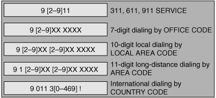
When using the 9.@ route pattern, Cisco CallManager recognizes that dialing is complete when the user dials 1 + 10 digits (signifying long-distance dialing) or just dials 10 digits (local area codes without the 1). If the number dialed does not begin with a 1, Cisco CallManager considers it a local area code and assumes that dialing is complete after 10 digits.
In an area where seven digits are dialed for local numbers, Cisco CallManager cannot recognize which office exchange codes (NXXs) to use for routing unless you specifically code them as route patterns.
Note
NXX is the central office (CO) exchange code, which consists of three digits that designate a particular CO or a block of 10,000 subscriber lines. N is any digit between 2 and 9, and X is any digit between 0 and 9.
Generally, telephone company service providers arrange many NXXs in a given area code contiguously where you can use route pattern wildcards to assist in your configuration. Coding these individual route patterns for NXXs can be extremely difficult. You can use a route filter to simplify this procedure.
A route filter called seven-digit dialing is always preconfigured in Cisco CallManager. You should assign this route filter to any 9.@ route pattern in an area that uses seven-digit dialing. This route filter removes all local area codes. If a dialed number does not begin with a 1, then it is a seven-digit number, and Cisco CallManager considers dialing complete after seven digits. This situation requires you to configure local area codes specifically as separate route patterns. Doing so is generally not an issue because the number of area codes in a geographical region is usually small.
Note
Route filters are only used with the @ route pattern and are not necessary if you have configured a robust dial plan (that does not use the @ route pattern).
Route Filter Tags
You can design and configure route filters using a number of predefined tags in the Cisco CallManager CCMAdmin web utility. Table 11-1 provides a list of tags available to you when implementing route filters.
|
Tag Name |
Example Pattern |
Description |
|---|---|---|
|
AREA-CODE |
1 214 555 1212 |
The area code in an 11-digit long-distance call |
|
COUNTRY-CODE |
011 33 123456# |
The country code in an international call |
|
END-OF-DIALING |
011 33 123456# |
The #, which terminates interdigit timeout for an international call |
|
INTERNATIONAL-ACCESS |
01 1 33 123456# |
The initial 01 of an international call |
|
INTERNATIONAL-DIRECT-DIAL |
01 1 33 123456# |
The digit that denotes the direct-dial component of an international call |
|
INTERNATIONAL OPERATOR |
01 0 |
The digit that denotes the operator component of an international call |
|
LOCAL-AREA-CODE |
214 555 1212 |
The area code in a 10-digit local call |
|
LOCAL-DIRECT-DIAL |
1 555 1212 |
The initial 1 that is required for some 7-digit calls |
|
LOCAL-OPERATOR |
0 555 1212 |
The initial 0 that is required for operator-assisted local calls |
|
LONG-DISTANCE-DIRECT-DIAL |
1 214 555 1212 |
The initial 1 that is required for long-distance direct-dialed calls |
|
LONG-DISTANCE-OPERATOR |
0 214 555 1212 |
The initial 0 that is required for operator-assisted long-distance calls |
|
NATIONAL-NUMBER |
011 33 123456# |
The national number component of an international call |
|
OFFICE-CODE |
1 214 555 1212 |
The office exchange code of a North American call |
|
SATELLITE-SERVICE |
011 88141234# |
A specific value that is associated with calls to the satellite country code |
|
SERVICE |
1 411 |
A value that provides access to local telephony provider services |
|
SUBSCRIBER |
1 214 555 1212 |
A particular extension that is served by a given exchange |
|
TRANSIT-NETWORK |
101 0321 1 214 555 1212 |
A long-distance carrier code |
|
TRANSIT-NETWORK-ESCAPE |
101 0321 1 214 555 1212 |
The escape sequence that is used for entering a long-distance carrier code |
Configuring Route Filters
Route filter configuration occurs in two major steps:
|
Step 1. |
Configure route filter with necessary tags and arguments. |
|
Step 2. |
Apply the route filter to a route pattern or translation pattern. |
Just as with access lists on routers, you can create route filters all day and they will never make any difference until you have applied them. Just like an access list, the sole purpose of a route filter is to match criteria; how you apply the route filter determines if the criteria is permitted or denied.
To configure a route filter, use the Cisco CallManager Administration window:
|
Step 1. |
Choose the Route Plan menu. |
|
Step 2. |
Choose Route Filter from the menu bar. |
|
Step 3. |
Click the Add a New Route Filter hyperlink. |
|
Step 4. |
Choose North American Numbering Plan from the Dial Plan menu. |
|
Step 5. |
Enter a name in the Route Filter Name field. The name can consist of up to 50 alphanumeric characters, and can contain any combination of spaces, periods (.), hyphens (-), and underscore characters (_). Each route filter name must be unique to the route plan. |
After you have accomplished these initial steps, the Route Filter Clause Configuration window appears, as shown in Figure 11-2.
Figure 11-2. Route Filter Clause Configuration Window
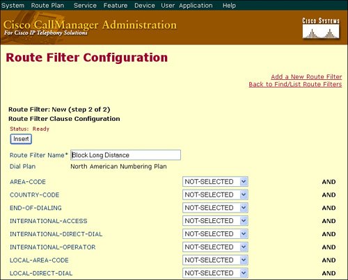
From this point, you can combine your tags with operators to define match conditions. Table 11-2 describes the four operators available when configuring route filters.
|
Operator |
Description |
|---|---|
|
NOT-SELECTED |
Do not filter calls based on the dialed digit string associated with this tag. |
|
EXISTS |
Filter calls when the dialed digit string associated with this tag is found. |
|
DOES-NOT-EXIST |
Filter calls when the dialed digit string associated with this tag is not found. |
|
== |
Filter calls when the dialed digit string associated with this tag matches the specified value. |
The following are examples of match conditions using route filter tags and operators:
- A route filter that uses the tag AREA-CODE and the operator DOES-NOT-EXIST selects all dialed digit strings that do not include an area code.
- A route filter that uses the tag AREA-CODE, the operator = =, and the entry 515 selects all dialed digit strings that include the 515 area code.
- A route filter that uses the tag AREA-CODE, the operator = =, and the entry 5[2-9]X selects all dialed digit strings that include area codes in the range of 520 through 599.
- A route filter that uses the tag TRANSIT-NETWORK, the operator ==, and the entry 0288, along with the tag TRANSIT-NETWORK-ESCAPE, the operator ==, and the entry 101, selects all dialed digit strings with the carrier access code 1010288.
Applying Route Filters
After you have configured the route filter, you must apply them to a route pattern or translation pattern to define the permit or deny action.
Note
Translation patterns are discussed later in this chapter.
To apply the route filter you have created to a route pattern, perform the following steps:
|
Step 1. |
Choose the Route Plan > Route/Hunt > Route Pattern menu selection. |
|
Step 2. |
Choose the Add a New Route Pattern hyperlink. |
|
Step 3. |
Define the route pattern as @ (or 9.@) to represent the NANP. |
|
Step 4. |
Choose your configured route filter from the Route Filter drop-down list, as shown in Figure 11-3. Figure 11-3. Applying a Route Filter to a Route Pattern 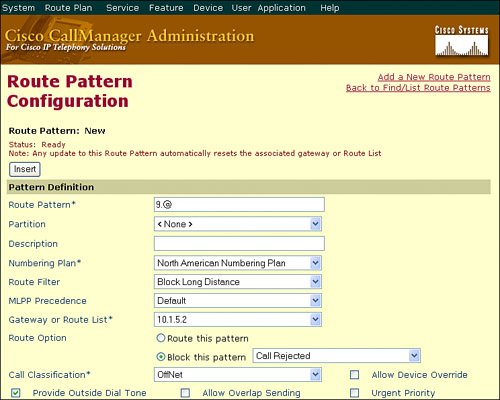
|
|
Step 5. |
Choose a PSTN exit gateway or route list. |
|
Step 6. |
Select the Route This Pattern radio button to allow the numbers matching the filter to route to the PSTN or select the Block This Pattern radio button to block the numbers matching the filter from reaching the PSTN. |
Practical Route Filter Example
To demonstrate route filter configuration, imagine that a company wanted to create a route filter that kept 1-900 numbers from being made available in the CallManager route plan. The first step would be to create a route filter that matched the area code 900, as shown in Figure 11-4.
Figure 11-4. Route Filter Matching the 900 Area Code
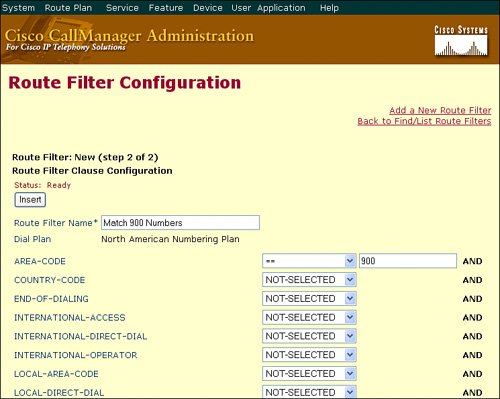
After the route filter has been added to the configuration, you then need to apply it to a route pattern to define the action required. Figure 11-5 illustrates the creation of a 9.@ route pattern (representing the NANP) with the Match 900 Numbers route filter applied. The key action rests in the Route This Pattern or Block This Pattern radio buttons. If you select to Route This Pattern, you would add only 900 numbers to the Cisco CallManager route plan. Unless you had a very strange organization, this is not a desired effect. Rather, you would select the Block This Pattern radio button to block any numbers containing the 900 area code.
Figure 11-5. Route Pattern Configuration

CallManager allows you to configure multiple 9.@ route patterns, provided each has a unique route filter configuration. This provides flexibility when creating your route plan. By combining multiple 9.@ route patterns with unique route filters, you can route (or block) exactly what you want from the CallManager route plan.
Tip
You could also accomplish this same objective by creating a route pattern of 1900XXXXXXX and choosing Block this Pattern under the route pattern configuration.
Discard Digit Instructions |
Part I: Cisco CallManager Fundamentals
Introduction to Cisco Unified Communications and Cisco Unified CallManager
Cisco Unified CallManager Clustering and Deployment Options
- Cisco Unified CallManager Clustering and Deployment Options
- The Two Sides of the Cisco Unified CallManager Cluster
- Cluster Redundancy Designs
- Call-Processing Deployment Models
- Summary
- Review Questions
Cisco Unified CallManager Installation and Upgrades
- Cisco Unified CallManager Installation and Upgrades
- Cisco Unified CallManager 4.x Clean Installation Process
- Upgrading Prior Cisco Unified CallManager Versions
- Summary
- Review Questions
Part II: IPT Devices and Users
Cisco IP Phones and Other User Devices
Configuring Cisco Unified CallManager to Support IP Phones
- Configuring Cisco Unified CallManager to Support IP Phones
- Configuring Intracluster IP Phone Communication
- IP Phone Configuration
- Case Study: Device Pool Design
- Summary
- Review Questions
Cisco IP Telephony Users
- Cisco IP Telephony Users
- Cisco CallManager User Database
- Cisco CallManager User Configuration
- User Logon and Device Configuration
- Summary
- Review Questions
Cisco Bulk Administration Tool
- Cisco Bulk Administration Tool
- The Cisco Bulk Administration Tool
- Using the Tool for Auto-Registered Phone Support
- Summary
- Review Questions
Part III: IPT Network Integration and Route Plan
Cisco Catalyst Switches
- Cisco Catalyst Switches
- Catalyst Switch Role in IP Telephony
- Powering the Cisco IP Phone
- Data and Voice VLANs
- Configuring Class of Service
- Summary
- Review Questions
Configuring Cisco Gateways and Trunks
- Configuring Cisco Gateways and Trunks
- Cisco Gateway Concepts
- Configuring Access Gateways
- Cisco Trunk Concepts
- Configuring Intercluster Trunks
- SIP and Cisco CallManager
- Summary
- Review Questions
Cisco Unified CallManager Route Plan Basics
- Cisco Unified CallManager Route Plan Basics
- External Call Routing
- Route Plan Configuration Process
- Summary
- Review Questions
Cisco Unified CallManager Advanced Route Plans
- Cisco Unified CallManager Advanced Route Plans
- Route Filters
- Discard Digit Instructions
- Transformation Masks
- Translation Patterns
- Route Plan Report
- Summary
- Review Questions
Configuring Hunt Groups and Call Coverage
- Configuring Hunt Groups and Call Coverage
- Call Distribution Components
- Configuring Line Groups, Hunt Lists, and Hunt Pilots
- Summary
- Review Questions
Implementing Telephony Call Restrictions and Control
- Implementing Telephony Call Restrictions and Control
- Class of Service Overview
- Partitions and Calling Search Spaces Overview
- Time-of-Day Routing Overview
- Configuring Time-of-Day Routing
- Time-of-Day Routing Usage Scenario
- Summary
- Review Questions
Implementing Multiple-Site Deployments
- Implementing Multiple-Site Deployments
- Call Admission Control
- Survivable Remote Site Telephony
- Summary
- Review Questions
Part IV: VoIP Features
Media Resources
- Media Resources
- Introduction to Media Resources
- Conference Bridge Resources
- Media Termination Point Resources
- Annunciator Resources
- Transcoder Resources
- Music on Hold Resources
- Media Resource Management
- Summary
- Review Questions
Configuring User Features, Part 1
- Configuring User Features, Part 1
- Basic IP Phone Features
- Softkey Templates
- Enhanced IP Phone Features
- Barge and Privacy
- IP Phone Services
- Summary
- Review Questions
Configuring User Features, Part 2
- Configuring User Features, Part 2
- Cisco CallManager Extension Mobility
- Client Matter Codes and Forced Authentication Codes
- Call Display Restrictions
- Malicious Call Identification
- Multilevel Precedence and Preemption
- Summary
- Review Questions
Configuring Cisco Unified CallManager Attendant Console
- Configuring Cisco Unified CallManager Attendant Console
- Introduction to Cisco CallManager Attendant Console
- Call Routing and Call Queuing
- Server and Administration Configuration
- Cisco Attendant Console Features
- Summary
- Review Questions
Configuring Cisco IP Manager Assistant
- Configuring Cisco IP Manager Assistant
- Cisco IP Manager Assistant Overview
- Cisco IP Manager Assistant Architecture
- Configuring Cisco IPMA for Shared-Line Support
- Summary
- Review Questions
Part V: IPT Security
Securing the Windows Operating System
- Securing the Windows Operating System
- Threats Targeting the Operating System
- Security and Hot Fix Policy
- Operating System Hardening
- Antivirus Protection
- Cisco Security Agent
- Administrator Password Policy
- Common Windows Exploits
- Security Taboos
- Summary
- Review Questions
Securing Cisco Unified CallManager Administration
- Securing Cisco Unified CallManager Administration
- Threats Targeting Remote Administration
- Securing CallManager Communications Using HTTPS
- Multilevel Administration
- Summary
- Review Questions
Preventing Toll Fraud
- Preventing Toll Fraud
- Toll Fraud Exploits
- Preventing Call Forward and Voice-Mail Toll Fraud Using Calling Search Spaces
- Blocking Commonly Exploited Area Codes
- Using Time-of-Day Routing
- Using FAC and CMC
- Restricting External Transfers
- Dropping Conference Calls
- Summary
- Review Questions
Hardening the IP Phone
Understanding Cryptographic Fundamentals
- Understanding Cryptographic Fundamentals
- What Is Cryptography?
- Symmetric Encryption
- Asymmetric Encryption
- Hash Functions
- Digital Signatures
- Summary
- Review Questions
Understanding the Public Key Infrastructure
- Understanding the Public Key Infrastructure
- The Need for a PKI
- PKI as a Trusted Third-Party Protocol
- PKI Entities
- PKI Enrollment
- PKI Revocation and Key Storage
- PKI Example
- Summary
- Review Questions
Understanding Cisco IP Telephony Authentication and Encryption Fundamentals
- Understanding Cisco IP Telephony Authentication and Encryption Fundamentals
- Threats Targeting the IP Telephony System
- How CallManager Protects Against Threats
- PKI Topologies in Cisco IP Telephony
- PKI Enrollment in Cisco IP Telephony
- Keys and Certificate Storage in Cisco IP Telephony
- Authentication and Integrity
- Encryption
- Summary
- Review Questions
Configuring Cisco IP Telephony Authentication and Encryption
- Configuring Cisco IP Telephony Authentication and Encryption
- Authentication and Encryption Configuration Overview
- Enabling Services Required for Security
- Using the CTL Client
- Working with Locally Significant Certificates
- Configuring the Device Security Mode
- Negotiating Device Security Mode
- Generating a CAPF Report
- Summary
- Review Questions
Part VI: IP Video
Introducing IP Video Telephony
- Introducing IP Video Telephony
- IP Video Telephony Solution Components
- Video Call Concepts
- Video Protocols Supported in Cisco CallManager
- Bandwidth Management
- Call Admission Control Within a Cluster
- Call Admission Control Between Clusters
- Summary
- Review Questions
Configuring Cisco VT Advantage
- Configuring Cisco VT Advantage
- Cisco VT Advantage Overview
- How Calls Work with Cisco VT Advantage
- Configuring Cisco CallManager for Video
- Configuring Cisco IP Phones for Cisco VT Advantage
- Installing Cisco VT Advantage on a Client
- Summary
- Review Questions
Part VII: IPT Management
Introducing Database Tools and Cisco Unified CallManager Serviceability
- Introducing Database Tools and Cisco Unified CallManager Serviceability
- Database Management Tools
- Cisco CallManager Serviceability Overview
- Tools Overview
- Summary
- Review Questions
Monitoring Performance
- Monitoring Performance
- Performance Counters
- Microsoft Event Viewer
- Microsoft Performance Monitor
- Real-Time Monitoring Tool Overview
- Summary
- Review Questions
Configuring Alarms and Traces
- Configuring Alarms and Traces
- Alarm Overview
- Alarm Configuration
- Trace Configuration
- Trace Analysis
- Trace Collection
- Bulk Trace Analysis
- Additional Trace Tools
- Summary
- Review Questions
Configuring CAR
- Configuring CAR
- CAR Overview
- CAR Configuration
- Report Scheduling
- System Database Configuration
- User Report Configuration
- Summary
- Review Questions
Using Additional Management and Monitoring Tools
- Using Additional Management and Monitoring Tools
- Remote Management Tools
- Dependency Records
- Password Changer Tool
- Cisco Dialed Number Analyzer
- Quality Report Tool
- Summary
- Review Questions
Part VIII: Appendix
Appendix A. Answers to Review Questions
Index
EAN: 2147483647
Pages: 329
