GDI+ Basics
Overview
.NET provides a new framework of classes for two-dimensional drawing and rendering. Taken together, these classes, found in the five System.Drawing namespaces (and contained in the System.Drawing.dll assembly), represent GDI+.
Technically, GDI+ still relies on the same low-level Windows APIs you may have used in Windows programming of the past. The APIs were often referred to as GDI (Graphics Device Interface). The central idea behind these GDI functions was that the programmer could write text and images to different devices (printers, monitors, and video cards), without needing to understand the underlying hardware. In turn, Windows ensured wide client compatibility, and made use of any optimizations that the hardware might provide. Unfortunately, the GDI functions required a lot of coding wizardry.
The GDI+ types in .NET are object-oriented wrappers over the low-level GDI functions and, strictly speaking, they don't add any new capabilities. However, the .NET types provide a higher level of abstraction, with convenient support for geometric transformations, antialiasing, and palette blending. Many of these techniques required a painful amount of tiresome coding (and lucky insights) to pull off in the past.
You've already seen GDI+ at work throughout this book. In fact, a number of the more advanced examples would have been impossible without it. A few examples include:
- In Chapter 3, you saw many of the basic GDI+ ingredients in the System.Drawing namespace, including objects representing fonts, colors, position (points), and size (rectangles).
- In Chapter 4, you saw an owner-drawn menu that created menu entries using text and a thumbnail icon.
- In Chapter 5, you saw irregularly shaped forms that construct and outline their borders with a graphics path.
- In Chapter 6, you saw how ImageList images could be drawn on a form's surface.
- In Chapter 9, you saw a custom DataGrid column that draws text content and an icon.
This chapter explains the underlying GDI+ framework that makes all this possible.
 Companion Web Site
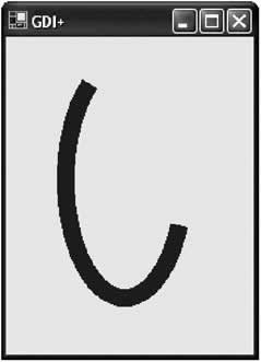
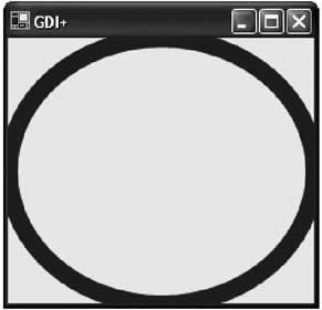
Optimizing GDI+ PaintingPainting is a performance-sensitive area for any application. Slow rendering may not stop your application from performing its work, but screen flicker and slow painting can make it seem unprofessional. This section considers some techniques that optimize drawing with GDI+ surfaces. Painting and ResizingOne often overlooked fact about automatic repainting is that it only affects the portion of the window that is obscured. This is particularly important with window resizing. For example, consider the slightly modified Paint code that follows, which paints an ellipse that is the same size as the containing window. The result is pictured in Figure 12-3.
private void form1_Paint(object sender, System.Windows.Forms.PaintEventArgs e)
{
 Pen drawingPen = new Pen(Color.Red, 15);
 e.Graphics.DrawEllipse(DrawingPen, New Rectangle(new Point(0, 0),
 this.ClientSize));
}
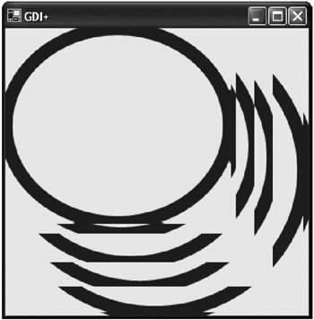
When you resize this window, you'll discover that the painting code isn't working correctly. The newly exposed portions of the window are filled with the resized ellipse, but the rest of the window is not updated, leading to the mess shown in Figure 12-4.
The problem is that Windows assumes that it only needs to repaint the portion of the window that has been hidden or restored. In this case, the entire content of the window depends on its dimensions, so the assumption is incorrect. Fortunately, you can solve this problem by manually invalidating the code whenever the form is resized (by handling the resize event, as shown below, or overriding the OnResize() method).
private void form1_Resize(object sender, System.EventArgs e)
{
 this.Invalidate();
}
With the addition of this code, the entire form is repainted and the ellipse grows or shrinks to fit the window bounds perfectly. Another option would be to set the Form.ResizeRedraw property to true. Painting Portions of a WindowIn some cases, it just doesn't make sense to repaint the entire window when you only need to update a portion of the display. One example is a drawing program. Consider a simple example program that allows the user to draw squares. When the user clicks with the mouse, a square is created, but not directly drawn. Instead, a rectangle object is added to a special ArrayList collection so it can be tracked, and the form is invalidated.
// Store the squares that are painted on the form.
ArrayList squares = new ArrayList();

// This code reacts to the Form.MouseDown event.
private void DrawSquare_MouseDown(object sender,
 System.Windows.Forms.MouseEventArgs e)
{
 Rectangle square = new Rectangle(e.X, e.Y, 20, 20);
 squares.Add(square);
 this.Invalidate();
}
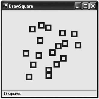
The painting logic then takes over, iterating through the collection, and drawing each rectangle. The number of squares that are currently being displayed is also written to a status bar.
private void DrawSquare_Paint(object sender,
 System.Windows.Forms.PaintEventArgs e)
{
 Pen drawingPen = new Pen(Color.Red, 10);
 foreach (Rectangle square in squares)
 {
 e.Graphics.DrawRectangle(drawingPen, square);
 }

 pnlSquares.Text = " " + squares.Count.ToString() + " squares";
}
The result of a paint operation is shown in Figure 12-5.
The problem with this code is that every time a rectangle is created, the entire form is redrawn. This causes noticeable screen flicker as the number of squares advances beyond 100. You can try this out yourself using the GDI+ Basics project included with the code for this chapter. There are two ways that you can remedy this problem. The fastest solution is to draw the square in two places: in the Paint logic and the MouseDown event handling code. With this approach, the MouseDown event handler does not need to invalidate the form. It draws the square directly, and stores enough information about the new rectangle for it to be successfully repainted if the window is minimized and restored. The potential drawback is that the code becomes significantly more tangled. If you are drawing a more complex object, you might be able to separate the drawing logic into a separate subroutine that accepts a Graphics object and the item to draw, as shown in the following code snippet.
// Paint a square in response to a mouse click.
private void DrawSquare_MouseDown(object sender,
 System.Windows.Forms.MouseEventArgs e)
{
 Rectangle square = new Rectangle(e.X, e.Y, 20, 20);
 squares.Add(square);

 Graphics g = this.CreateGraphics();
 DrawRectangle(square, g);
 g.Dispose();
}
// Paint all the squares when the form needs to be refreshed
// in response to the Paint event.
private void DrawSquare_Paint(object sender,
 System.Windows.Forms.PaintEventArgs e)
{
 foreach (Rectangle square in squares)
 {
 DrawRectangle(square, e.Graphics);
 }
}

// This procedure performs the actual drawing, and is called by
// DrawSquare_MouseDown and DrawSquare_Paint.
private void DrawRectangle(Rectangle rect, Graphics g)
{
 Pen drawingPen = new Pen(Color.Red, 10);
 g.DrawRectangle(drawingPen, rect);
}
A simpler approach is to use one of the overloaded versions on the Invalidate() method. This instructs Windows to repaint only a small portion of the window. The full painting code still runs (which could slow your application if the painting is complex), but only the specified region is repainted, thereby improving performance and drastically reducing screen flicker.
private void DrawSquare_MouseDown(object sender,
 System.Windows.Forms.MouseEventArgs e)
{
 Rectangle square = new Rectangle(e.X, e.Y, 20, 20);
 squares.Add(square);
 this.Invalidate(square);
}
Another way to paint just a portion of a window, and achieve better performance, is to develop owner-drawn controls that override their own OnPaint() methods.
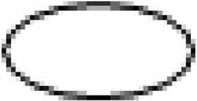
Rendering Mode and AntialiasingOne factor that's hampered the ability of drawing tools in other programming frameworks (like Visual Basic) is the lack of control over rendering quality. With GDI+, however, you can enhance the quality of your drawing with automatic antialiasing. Antialiasing is a technique used to smooth out jagged edges in shapes and text. It works by adding shading at the border of an edge. For example, grey shading might be added to the edge of a black curve to make a corner look smoother. Technically, antialiasing blends a curve with its background. Figure 12-6 shows a close-up of an antialiased ellipse.
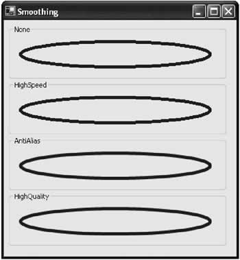
To use smoothing in your applications, you set the SmoothingQuality property of the Graphics object. You can choose between None, HighSpeed (the default), AntiAlias, and HighQuality (which is similar to AntiAlias but uses other, slower optimizations with LCD screens). The Graphics.SmoothingQuality property is one of the few stateful Graphics class members. That means that you set it before you begin drawing, and it applies to any text or shapes you draw in the rest of the paint session (until the Graphics object is disposed of). e.Graphics.SmoothingMode = Drawing.Drawing2D.SmoothingMode.AntiAlias; Figure 12-7 shows a form with several picture boxes. Each picture box handles its own paint event, sets a different smoothing mode, and then draws an ellipse.
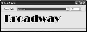
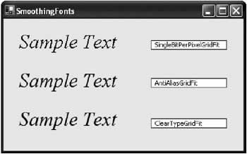
Antialiasing can also be used with fonts to soften jagged edges on text. The latest versions of the Windows operating system use antialiasing automatically with on-screen fonts. However, you can set the Graphics.TextRenderingHint property to ensure optimized text. You can choose between SingleBitPerPixelGridFit (fastest performance and lowest quality), AntiAliasGridFit (better quality but slower performance), and ClearTypeGridFit (the best quality on an LCD display). Or, you can use the SystemDefault value to use whatever font smoothing settings the user has configured. Figure 12-8 compares different font smoothing modes.
Double BufferingYou may notice that when you repaint a window frequently it flickers madly. The flicker is caused by the fact that with each paint event, the image is first erased and then redrawn object by object. The flash you see is the blank background that precedes the redrawn content. You can reduce flickering by preventing a control or form from drawing its background. If you do, your code must begin by painting a background using one of the fill methods from the Graphics class. Otherwise, the original content remains underneath the new content. To disable background painting, all you need to do is override the OnPaintBackground() method for the form or control and do nothing. In other words, you won't call the base OnPaintBackground() method.
protected override void OnPaintBackground(
 System.Windows.Forms.PaintEventArgs pevent)
{
 // Do nothing.
}
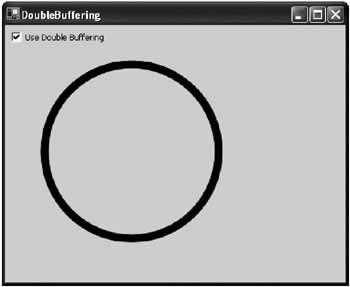
If you are filling a form or control with a custom background color, you should always follow this step, as it can improve performance dramatically. Otherwise, your window will flicker noticeably between the default background color and the color you paint every time you redraw the form. Disabling the automatic background painting reduces flicker, but the flicker remains. To remove it completely, you can use a technique known as double buffering. With double buffering, an image is built in memory instead of on the surface of a form or control. When the image is completed, it's drawn directly to the form. The process of drawing takes just as long, but the refresh is faster because it is delayed until the image is completely rendered. Hence, there is very little flicker. To use double buffering, you need to create an Image object. You then draw on the in-memory Image object using the Graphics methods. Finally, you copy the fully rendered image to the form. One good way to test double buffering is to create a form that is frequently refreshed. The next example presents a form with an ellipse that grows and shrinks automatically (see Figure 12-9). The form is redrawn in response to the tick of a Timer control.
Here's the timer code:
private bool isShrinking = false;
private int extraSize = 0;

// This code is triggered in response to the timer tick.
private void tmrRefresh_Tick(object sender,
 System.EventArgs e)
{
 // Change the circle dimensions.
 if (isShrinking)
 {
 extraSize--;
 }
 else
 {
 extraSize++;
 }

 // Change the sizing direction if needed.
 if (extraSize > (this.Width - 150))
 {
 isShrinking = true;
 }
 else if (extraSize < 1)
 {
 isShrinking = false;
 }

 // Repaint the form.
 this.Invalidate();
}
The paint code examines the state of a check box and decides whether or not it will implement double buffering.
private void DoubleBuffering_Paint(object sender,
 System.Windows.Forms.PaintEventArgs e)
{
 Graphics g;
 Bitmap drawing = null;

 // Check if double buffering is needed, and assign the GDI+ context.
 if (chkDoubleBuffer.Checked)
 {
 drawing = new Bitmap(this.Width, this.Height, e.Graphics);
 g = Graphics.FromImage(drawing);
 }
 else
 {
 g = e.Graphics;
 }

 g.SmoothingMode = System.Drawing.Drawing2D.SmoothingMode.HighQuality;
 // Draw a rectangle.
 Pen drawingPen = new Pen(Color.Black, 10);
 g.FillRectangle(Brushes.White, new Rectangle(new Point(0, 0),
 this.ClientSize));
 g.DrawEllipse(drawingPen, 50, 50, 50 + extraSize, 50 + extraSize);

 // If using double buffering, render the final image and dispose of it.
 if (chkDoubleBuffer.Checked)
 {
 e.Graphics.DrawImageUnscaled(drawing, 0, 0);
 g.Dispose();
 }
}
When you test this application, you'll see that there is absolutely no flicker in double-buffered mode. There is significant flicker without it.
Painting and DebuggingDebugging drawing code can sometimes be frustrating. For example, consider what happens if you set a breakpoint in the painting code. When the breakpoint is reached, the code enters break mode, the IDE appears, and the window is hidden. When you run the next line of code, the program is redisplayed, and a new Paint event is triggered. To escape this endless sequence of repainting, you can use a couple of tricks:
|
|||||||||||||||||||||
The Graphics ClassThe majority of the GDI+ drawing smarts is concentrated in the Graphics class. Table 12-1 describes the basic set of Graphics class members, many of which are explored in detail as the chapter progresses.
The Graphics class also provides a slew of methods for drawing specific shapes, images, or text. Most of these methods begin with the word "Draw." All shape-drawing methods draw outlines; you need to use the corresponding "Fill" method to paint an interior fill region. Most of the methods in Table 12-2 are self-explanatory. Two interesting methods that I haven't described yet include DrawPath() and FillPath(), which work with the GraphicsPath class in the System.Drawing.Drawing2D namespace.
The GraphicsPath class encapsulates a series of connected lines, curves, and text. You used the GraphicsPath class in Table 12-3 to add all the required elements. GraphicsPath path = new GraphicsPath(); path.AddEllipse(0, 0, 100, 50); path.AddRectangle(New Rectangle(100, 50, 100, 50);
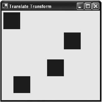
Optionally, you can also create a solid filled figure out of lines. To do this, you first call the StartFigure() method. Then you add the required curves and lines using the appropriate methods. When finished, you call the CloseFigure() method to close off the shape by drawing a line from the endpoint to the starting point. You can use these methods multiple times to add several closed figures to a single GraphicsPath object. GraphicsPath path = new GraphicsPath(); path.StartFigure(); path.AddArc(10, 10, 100, 100, 20, 50); path.AddLine(20, 100, 70, 230); path.CloseFigure(); Optionally, you can create a solid-filled figure out of lines. To do this, you first call the StartFigure() method. Then you add the required curves and lines using the appropriate methods. When finished, you call the CloseFigure() method to close off the shape by drawing a line from the endpoint to the starting point. You can use these methods multiple times to add several closed figures to a single GraphicsPath object. GraphicsPath path = new GraphicsPath(); path.StartFigure(); path.AddArc(10, 10, 100, 100, 20, 50); path.AddLine(20, 100, 70, 230); path.CloseFigure(); Coordinate Systems and TransformationsBy default, when you draw GDI+ shapes, you use a coordinate system that designates the top left corner as (0, 0). The x-axis value increases as you move to the right, and the y-axis value increases as you move down. The point (this.Width, this.Height) corresponds to the bottom-right corner of a form (discounting the title bar region). Each unit corresponds to one pixel. This is nothing new-it's the same coordinate system you examined when I introduced control basics in Chapter 3. However, the Graphics class also gives you the flexibility to change the unit of measurement, point of origin, and rotation. To change the unit of measurement, you simply set the PageUnit property of the Graphics class. You can use one of several values from the GraphicsUnitClass, including Display (1/75 of an inch), Document (1/300 inch), Inch, Millimeter, Pixel (the default), and Point (1/72 of an inch). e.Graphics.PageUnit = Graphics.Inch; The ability to change the point of origin is more useful. It uses the Graphics.TranslateTranform() method, which accepts the coordinates of the new point that should become (0,0). Using the code below, the point at (50, 50) will become the new (0,0) origin. Points to the left or right of this origin must be specified using negative values. e.Graphics.TranslateTransform(50, 50); This is a fairly handy trick. For example, it can allow you to perform simple calculations by assuming the top left point of your drawing is (0, 0), but gives you the freedom to add a border between the drawing and the form by translating the coordinate system before you begin to draw. You could even use this method several times with different points and repeat the same drawing code. The figure you are drawing would then appear at several different points in the window, as shown in Figure 12-10.
private void Transform_Paint(object sender,
 System.Windows.Forms.PaintEventArgs e)
{
 // Draw several squares in different places.
 DrawRectangle(e.Graphics);
 e.Graphics.TranslateTransform(180, 60);
 DrawRectangle(e.Graphics);
 e.Graphics.TranslateTransform(-50, 80);
 DrawRectangle(e.Graphics);
 e.Graphics.TranslateTransform(-100, 50);
 DrawRectangle(e.Graphics);
}

private void DrawRectangle(Graphics g)
{
 Pen drawingPen = new Pen(Color.Red, 30);

 // Draw a rectangle at a fixed position.
 g.DrawRectangle(drawingPen, new Rectangle(20, 20, 20, 20));
}
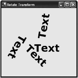
The final transformation considered here is a rotational one. It uses the Graphics.RotateTransform() method, which rotates the coordinate system using an angle or matrix. The important fact to remember is that rotations are performed around the point of origin. If you haven't performed any translation transformations, this will be in the top right corner of the form. The next example uses a translation transform to move the center point to the middle of the form, and then rotates text around that point with successive rotational transforms. The result is shown in Figure 12-11.
private void RotateTransform_Paint(object sender,
 System.Windows.Forms.PaintEventArgs e)
{
 // Optimize text quality.
 e.Graphics.TextRenderingHint = TextRenderingHint.AntiAliasGridFit;

 // Move origin to center of form so we can rotate around that.
 e.Graphics.TranslateTransform(this.Width / 2 - 30, this.Height / 2 - 30);

 DrawText(e.Graphics);
 e.Graphics.RotateTransform(45);
 DrawText(e.Graphics);
 e.Graphics.RotateTransform(75);
 DrawText(e.Graphics);
 e.Graphics.RotateTransform(160);
 DrawText(e.Graphics);
}

private void DrawText(Graphics g)
{
 g.DrawString("Text", new Font("Verdana", 30, FontStyle.Bold),
 Brushes.Black, 0, 10);
}
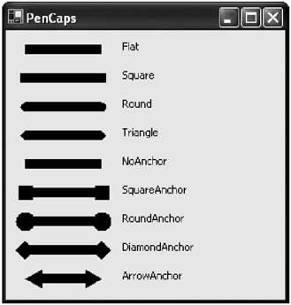
PensIn Chapter 3, you learned about many of the GDI+ basics, including fonts, colors, points, and rectangles. However, GDI+ drawing code also uses other details like brushes and pens. Pens are used to draw lines when you use the shape or curve drawing methods from the Graphics class. You can retrieve a standard pen using one of the static properties from the System.Drawing.Pens class. These pens all have a width of 1; they only differ in their color. Pen myPen = Pens.Black; You can also create a Pen object on your own, and configure all the properties described in Table 12-4. Pen myPen = new Pen(Color.Red); myPen.DashCap = DashCap.Triangle; myPen.DashStyle = DashDotDot; e.Graphics.DrawLine(myPen, 0, 0, 10, 0);
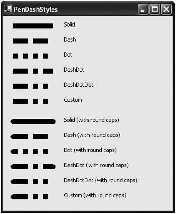
Figure 12-12 shows different line caps (which determine the appearance of the start and end of a line), while Figure 12-13 shows different dash styles.
BrushesBrushes are used to fill the space between lines. Brushes are used when drawing text or when using any of the fill methods of the Graphics class for painting the inside of a shape. You can quickly retrieve a predefined solid brush using a static property from the Brushes class, or the SystemBrushes class (which provides brushes that correspond to various Windows color scheme settings, like the control background color or the highlight menu text color). Brush myBrush = SystemBrushes.Menu; e.Graphics.FillRectangle(myBrush, 0, 0, 50, 50); Last, you can create a custom brush. You need to decide what type of brush you are creating. Solid brushes are created from the SolidBrush class, while other classes (HatchBrush, LinearGradientBrush, and TextureBrush) allow fancier options. The next three sections consider these different types of brushes.
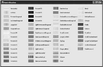
The HatchBrush A HatchBrush has a foreground color, a background color, and a hatch style that determines how these colors are combined. Typically, colors are interspersed using stripes, grids, or dots, but you can even select unusual pattern styles like bricks, confetti, weave, and shingles. Following is the code for a simple brush demonstration program that displays the available hatch brush styles. Figure 12-14 shows the result.
private void HatchBrushes_Paint(object sender,
 System.Windows.Forms.PaintEventArgs e)
{
 HatchBrush myBrush;
 int y = 20;
 int x = 20;

 // Enumerate over all the styles.
 foreach (HatchStyle brushStyle in System.Enum.GetValues(typeof(HatchStyle)))
 {
 myBrush = new HatchBrush(brushStyle, Color.Blue, Color.LightYellow);

 // Fill a rectangle with the brush.
 e.Graphics.FillRectangle(myBrush, x, y, 40, 20);

 // Display the brush name.
 e.Graphics.DrawString(brushStyle.ToString(), new Font("Tahoma", 8),
 Brushes.Black, 50 + x, y + 5);
 y += 30;
 if ((y + 30) > this.ClientSize.Height)
 {
 y = 20;
 x += 180;
 }
 }
}
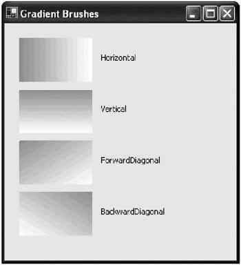
The LinearGradientBrush The LinearGradientBrush allows you to blend two colors in a gradient pattern. You can choose any two colors (as with the hatch brush) and then choose to blend horizontally (from left to right), vertically (from top to bottom), diagonally (from the top-left corner to the bottom-right), or diagonally backward (from the top-right to the bottom-left). You can also specify the origin point for either side of the gradient. Figure 12-15 shows the different gradient styles.
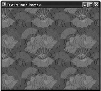
The TextureBrush Finally, the TextureBrush attaches a bitmap to a brush. The image is tiled in the painted portion of the brush, whether it is text or a simple rectangle. Here's an example that fills a form with a tiled bitmap. The result is shown in Figure 12-16.
private void TextureBrushExample_Paint(object sender,
 System.Windows.Forms.PaintEventArgs e)
{
 TextureBrush myBrush = new TextureBrush(Image.FromFile("tile.bmp"));
 e.Graphics.FillRectangle(myBrush, e.Graphics.ClipBounds);
}
|
||||||||||||||||||||||||||||||||||||||||||||||||||||||||||||||||||||||||||||||||||||||||||||||||||||||||||||||||||||||||||||||||||||||||||||||||||||||||||||||||||||||||||||||||||||||||||||||||||||||||||||||||||||||||||||||||||||||||||||||||
Hit TestingIn Chapter 11, you saw how you could build a simple drawing application by dynamically adding controls. An alternative (and potentially more lightweight) approach is to use GDI+ drawing structures. However, squares, ellipses, curves, and other shapes have no ability to capture mouse actions and raise the typical MouseDown and Click events. Instead, you need to intercept these events using the containing object (typically a form), and then manually determine if a shape was clicked. This process is known as hit testing. .NET provides basic hit testing support through a Contains() method that's built into the Rectangle structure. It examines a supplied x and y coordinate, Point object, or Rectangle object, and returns true if it is located inside the Rectangle. However, there are a couple of quirks that take some getting used to with Rectangle hit testing:
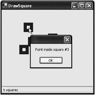
The next example uses hit testing with the square-drawing program developed earlier. When the user right-clicks the form, the code loops through the collection of squares, and displays a message box for each one that contains the clicked point (see Figure 12-17).
// Reacts to the Form.MouseDown event.
private void DrawSquare_MouseDown(object sender,
 System.Windows.Forms.MouseEventArgs e)
{
 if (e.Button == MouseButtons.Left)
 {
 // Add a square and update the screen.
 Rectangle square = new Rectangle(e.X, e.Y, 20, 20);
 squares.Add(square);
 this.Invalidate(square);
 }
 else if (e.Button == MouseButtons.Right)
 {
 // Search for the clicked square.
 int squareNumber = 0;
 foreach (Rectangle square in squares)
 {
 squareNumber++;
 if (square.Contains(e.X, e.Y))
 {
 MessageBox.Show("Point inside square #" +
 squareNumber.ToString());
 }
 }
 }
}
Once you have determined which square was clicked, you could modify it and then invalidate the form, or allow drag-and-drop as featured in Chapter 11.
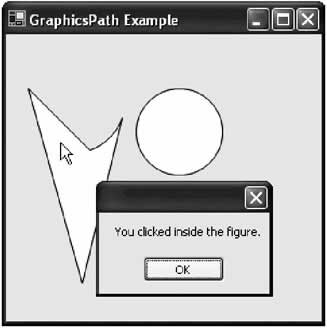
Hit Testing Nonrectangular Shapes.NET does provide some help if you need to perform hit testing with a nonrectangular object. If you use the GraphicsPath object to create a shape (or combination of shapes), you can rely on the indispensable IsVisible() method, which accepts a point and returns true if this point is contained inside a closed figure in the GraphicsPath. This method works equally well, whether you click inside a prebuilt closed figure (like a square, ellipse, polygon, and so on), or if you click inside a figure you created yourself with line segments using the StartFigure() and CloseFigure() methods of the GraphicsPath object.
private void GraphicsPathExample_Paint(object sender,
 System.Windows.Forms.PaintEventArgs e)
{
 e.Graphics.SmoothingMode = SmoothingMode.AntiAlias;
 path = new GraphicsPath();
 path.StartFigure();
 path.AddArc(10, 10, 100, 100, 20, 50);
 path.AddLine(20, 50, 70, 230);
 path.CloseFigure();
 path.AddEllipse(120, 50, 80, 80);
 e.Graphics.FillPath(Brushes.White, path);
 e.Graphics.DrawPath(Pens.Black, path);
}

// Reacts to the Form.MouseDown event.
private void GraphicsPathExample_MouseDown(object sender,
 System.Windows.Forms.MouseEventArgs e)
{
 if (path.IsVisible(e.X, e.Y))
 {
 MessageBox.Show("You clicked inside the figure.");
 }
}
Figure 12-18 shows a successful test of hit-testing with a nonrectangular shape. This technique is expanded in the next chapter into the basic framework for an advanced drawing program.
|
||||||||||||||||||
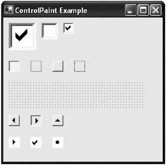
The ControlPaint ClassTechnically, the ControlPaint class isn't a part of GDI+. However, it's an extremely useful tool for custom control developers who use GDI+. It is also a well kept .NET secret. Essentially, the ControlPaint class offers methods for drawing standard Windows interface elements, like scroll buttons, borders, focus rectangles, and check boxes. This functionality is tremendously useful. For example, if you want to create a special control that contains a list of items with check boxes, you ordinarily have limited options. You can use control composition (and create contained CheckBox controls), but this limits the ways that you can use the check boxes and tailor the interface. Alternatively, you could attempt to draw your own, and probably end up with a rather crude looking square. With the ControlPaint class, however, you can use the DrawCheckBox() method, and end up with the perfectly shaded Windows standard for free. You can even create a check box of any size you like. Similarly, if you want to create a scroll button, or a button that displays a focus rectangle, you can also turn to the ControlPaint class. The ControlPaint class consists entirely of the static methods described in Table 12-5. Here's a line of code that uses it to draw a check box: ControlPaint.DrawCheckBox(e.Graphics, new Rectangle(10, 10, 50, 50), ButtonState.Checked);
And here's one that draws the familiar dotted focus rectangle: ControlPaint.DrawFocusRectangle(e.Graphics, New Rectangle(130, 80, 20, 20)); Figure 12-19 shows the sample output for several ControlPaint methods, including check boxes of different sizes and states. The next chapter develops a button control that uses ControlPaint to create its basic appearance.
Remember, this is a picture of a check box, not a check box! If you want it to change its state when the user clicks it, you need to manually repaint a new check box in a different state.
|
||||||||||||||||||||||||||||||||||||||||||||||||||||||||||||||||||||||||||
The Last WordIn this chapter you learned how to use .NET's revitalized painting framework, and the optimized techniques that make drawing routines sharp and flicker-free, including double buffering. You also considered topics you need to master if you want to develop your own owner-drawn controls, like hit testing and the ControlPaint class. The next chapter delves into interesting examples of custom control development with GDI+. |
|||||||||||||||
GDI+ Controls |
|||||||||||||||
Introduction
EAN: 2147483647
Pages: 142
