Project Management in a CM Environment
OVERVIEW
Configuration management (CM) must be meticulously planned and carefully managed if the organization is to achieve an effective, predictable, repeatable CM process. This principle is consistent with the concept of a software engineering project plan and, in effect, one can say that the project plan provides a subset of the overall CM plan (see Appendix T for a detailed Software Configuration Plan). Appendix X provides software configuration management (SCM) guidance for achieving the "Repeatable" level on the Software Engineering Institute (SEI) Capability Maturity Model .
Tasks associated with CM planning and management include:
- Identifying the scope and constraints of the project
- The creation of a written plan
- Implementation procedures
- Training
- Measurements
A typical CM plan will consist of the components shown in Table 2.1 [Bounds, 2001]. Those familiar with traditional systems development project planning will immediately see a similarity between this checklist and the contents of a typical project plan.
|
The remainder of this chapter ties together the principles of traditional project planning and configuration management planning and management.
WHO WRITES THE PROJECT PLAN
The project manager or team leader normally writes the project plan, although experienced consultants are often called in for this aspect of the project. When developing a project plan that is CM based, great care is taken to ensure that the planning process, and ultimately the developmental effort, are integrated and well-coordinated. This might seem obvious; however, integration and coordination are not things that are done well by most organizations. It has been proven that the vast majority of programming errors are due to interface problems. Similarly, the vast majority of configuration management problems are due to poor communications (i.e., interfaces) between the various departments and units that are tasked within the project plan.
In truth, there are as many ways to write a project plan as there are companies that write them. If the project is large, the proposed system might be divided into sub-systems each with its own team. Each team leader may need to write his or her own part of the project plan. The project manager then compiles each sub-plan into a plan for the entire project.
Another alternative is divide the project plan into discrete tasks and parcel out the effort to team members . Appendix A contains a sample project plan. As one can see from its table of contents, it is easily divisible.
WHAT GOES INTO THE PROJECT PLAN
Pressman has defined the prototypical project plan [Pressman 2001]. A student implementation of this guideline can be found in Appendix A and the reader is directed there for a concrete example of how to architect a project plan.
Section 1.0 introduces the system and describes its purpose. In this section, project scope and objectives need to be defined. In EIA-649 Configuration Management parlance [EIA 1998], this is referred to as the context and the environment. This sub-section contains a formal statement of scope, a description of major functions, concerns on performance issues, and a list of management and technical constraints.
A CM value-added project plan will answer most, if not all, of the following questions:
- Who are the customers?
- What are the attributes of the customer and end- user environments that need to be addressed by the CM?
- What role will the customer play in decisions about changes?
- What is the current phase of the life cycle, and what are the anticipated future phases?
- What is the technical complexity of the product?
- Are there any product components that require separate management attention?
- Is the product, or its components, a new design, an existing design, or a modification of an existing design?
- How complex a documentation package is necessary?
- If this product is already in the operational phase, what documentation is already available and is it current?
- What level of change activity, if any, is anticipated?
- What is the operational life of the product?
- What information will users require to run and maintain the system?
- How will this system interface to other systems?
The Section 2.0 discusses project estimates and resources. Historical data used for estimates needs to be specified, as do estimation techniques. As a result of the estimation process, the estimates of effort, cost, and duration need to be reported here. Resources are required to be discussed in terms of people and minimal hardware and software requirements.
The Section 3.0 discusses risk management strategy. A risk table needs to be created first, followed by more detailed discussions on risks to be managed. Based on that, a risk mitigation, monitoring, and management (contingency) plan needs to be created for each risk that has been addressed.
Section 4.0 is an actual project schedule in terms of deliverables and milestones. A project work breakdown structure (WBS) needs to be created, followed by a task network and a timeline chart (Gantt chart). In addition, a resource table describes the demand for and availability of resources by time windows . In a WBS, the total task is broken down into series of smaller tasks. The smaller tasks are chosen based on the size and the scope to fit in the management structure of the project. Therefore, efficient planning and execution are possible.
Section 5.0 discusses staff organization. Usually, a project is carried out by a group of people and therefore a team structure needs to be defined and a management reporting relationship specified.
Section 6.0 lays out a picture on tracking and control mechanisms. It can be divided into two sub-sections: (1) Quality Assurance (i.e., verification and audit) and Control and (2) Change Management and Control.
Project plans optimized for configuration management will also provide guidance for:
- Configuration identification
- Configuration status accounting
- Configuration management of digital data
- Subcontractor configuration management
At the end of the project plan, all supporting materials that do not fit into the body of the document can be attached in the "Appendices" section.
Most project managers have a difficult time when writing a project plan because it is often required at project inception. This, unfortunately , is when information is most scarce .
The project manager must choose the process model most appropriate for the project, and then define a preliminary plan based on the set of common process framework activities.
Afterward, process decomposition (partitioning) is carried out, generating a complete plan reflecting the work tasks required to populate the framework activities.
CM BASED PROJECT PLAN COMPONENTS
Identification
Configuration management requires that organizations develop a nomen-clature for identifying all the components of a work product. Configuration identification incrementally establishes and maintains the definitive current basis for control and status accounting of a system and its configuration items (CIs) throughout their life cycle (development, production, deployment, and operational support, until demilitarization and disposal). The configuration identification process ensures that all processes have common sets of documentation as the basis for developing a new system, modifying an existing component, buying a product for operational use, and providing support for the system and its components. The configuration identification process also includes identifiers that are shorthand references to items and their documentation. Good configuration control procedures assure the continuous integrity of the configuration identification. The configuration identification process includes:
- Selecting configuration items at appropriate levels of the product structure to facilitate the documentation, control, and support of the items and their documentation
- Determining the types of configuration documentation required for each CI to define its performance, functional, and physical attributes, including internal and external interfaces (configuration documentation provides the basis to develop and procure software, parts, and material; fabricate and assemble parts ; inspect and test items; and maintain systems)
- Determining the appropriate configuration control authority for each configuration document consistent with logistics support planning for the associated CI
- Issuing identifiers for the CIs and the configuration documentation
- Maintaining the configuration identification of CIs to facilitate effective logistics support of items in service
- Releasing configuration documentation and establishing configuration baselines for the configuration control of CIs
Because the project plan is one of the first documents in the long chain of systems development products, it must also adhere to the identification nomenclature developed by the organization.
Every organization has its own naming conventions. In general, the numbering system should include, at a minimum, the following information:
- System name
- Document/product type (e.g., "pp" for project plan, "srs" for systems requirement specification, etc.)
- Date
- Version number
A project plan is made up of multiple items ” for example, main report, appendices, images, charts , etc. Each of these should be duly numbered.
Software Scope
Determination of software scope should be ascertained first. One establishes software scope by answering questions about context, information objectives, function, performance, and reliability. The context usually includes hardware, existing software, users, documentation, complexity, maintenance, and work procedures. Normally, a system specification developed by a systems analyst supplies the information necessary to bound the scope.
Techniques such as Question and Answer sessions and FAST (Facilitated Application Specification Techniques) can be used to gather requirements and establish project scope [Zahniser 1990]. The following constitutes the minimum that needs to be ascertained:
- Major functions. These are the requirements by the customers for the software as to what it should be able to do.
- Performance issues. This aspect is about speed, response time, and other performance- related requirements. They can seriously impact the requirement of effort and should therefore be clarified here.
- Management and technical constraint. These constraints should be listed as a foundation for the next section's estimation.
Project Estimates
Estimation is the one activity that lays a foundation for all other project planning activities. However, a project manager should not be overly manic in estimation. If an iterative process model is adopted, it is possible to revisit and revise the estimates when customer requirements change.
Historical data is key to a good estimation. The availability of reliable historical software metrics from previous projects assists the project planner in translating the product size estimation into effort, time, and cost estimations. Baseline productivity metrics (e.g., LOC [lines of code] or FP [function points]) should be stored by project domain for use in future estimation efforts.
Estimation Techniques
If similar projects have already been completed, estimates can be easily based on that available data. Otherwise, either a decomposition technique or an empirical model can be used. There are also software tools that automate the process using the two preceding approaches. At least two estimation methods should be used, with the final estimation being a triangulation of the two. Even so, common sense and experience should be the ultimate judge.
In the example provided in Appendix A, two estimation methodologies are used:
- Process-based estimation, wherein the system is decomposed into discrete tasks such as analysis of the user interface and design of the user interface with an estimated amount of time allocated to each. For the Online Resource Scheduling System, the process-based estimate was 7.5 person-months.
- LOC (or line of code) estimation is much more difficult to estimate manually. A tool such as COCOMO (an abbreviation for Cost Construction Model) makes the effort much easier. A wealth of information as well as a free version of the COCOMO automated tool can be found on the CSE (Center for Software Engineering) Web site at (http://sunset.usc.edu/research/COCOMOII/index.html).
COCOMO II is a model that allows one to estimate the cost, effort, and schedule when planning a software developmental activity. It is based on the original COCOMO model devised by Dr. Barry Boehm in 1981 [Boehm 1981]. The COCOMO II model is actually derived from the following original mathematical formula that is described in the second half of this book:
m = c 1 * KLOC a * PROD[f i ]
COCOMO II permits the estimator to estimate a project cost in terms of lines of code (LOC) or function points (FP). FP calculation is quite complex. A chapter explaining function points can be found in this section.
Figure 2.1 shows the COCOMO II toolset in action. While a bit cumbersome ” the non-free COCOMO tools are much more user friendly ” the free version is quite functional. In this real-world example, the author used COCOMO to estimate the cost of building an Internet gaming system using the LOC option (see module size). Looking at the bottom of the screenshot, notice the three estimates: optimistic, most likely, and pessimistic. Thus, the planner needs to first estimate the size of the product to be built, and then translate that size estimate into human effort, calendar time, and dollars.
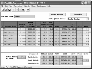
Figure 2.1: Using COCOMO for Estimation
A project plan that is CM based should also fully articulate the resources that are required to be deployed by the various departments involved in the systems development effort. In addition, the estimate should include time and materials for both training and verification and audit. In addition, a reasonable " futures -based" estimate should be attempted for maintenance.
Decomposition Techniques
According to Putnam and Myers [1992], several approaches can be used to handle the project sizing problem, including "Fuzzy-logic" sizing, which uses the approximate reasoning technique as in the art of "guestimating;" function point sizing; standard component sizing (i.e., modules, screens, reports , etc.); and change sizing, which is used in estimating the size of an effort to modify an existing system.
Problem-based estimation techniques include FP-and LOC-based estimation, which was just discussed. They both require the project planner to decompose the software into problem functions that can each be estimated individually. Then, the project planner estimates the LOC or FP (or other estimation variable) for each function and applies the baseline productivity metrics to derive the cost or effort for the function. Finally, these function estimates are combined to produce the overall estimate for the entire project. Alternatively, a process-based estimation is commonly used. Here, the process is partitioned into a relatively small set of activities (i.e., the large project is decomposed or segmented into more manageable tasks) or tasks, and the effort required to accomplish each is estimated.
Empirical Model
There are a variety of empirical models available to calculate the effort required based on the size estimation in FP or LOC. Other than COCOMO [Boehm 1981], the most widely used model is The Software Equation [Putman and Myers 1992].
Putnam's cost estimation model is a macro-estimation model. The model recognizes the relationship between cost and the amount of time available for the development effort. The Putnam model supports the mythical man-month idea first put forth by Frederick Brooks, which states that people and time are not always interchangeable. The Software Equation is explained in the second half of this book. The results of these estimation techniques are estimates of effort, cost, and duration. They, in turn , are used in other sections of the project plan.
Risk Management Strategy
A proactive risk strategy should always be adopted. It is better to plan for possible risk than have to react to it in a crisis. Software risks include project risks, technical risks, and business risks. They can also be categorized as known, predictable, or unpredictable risks. First, risks need to be identified. One method is to create a risk item checklist. The sample project plan in Appendix A (Table A4) lists the following risks:
- Customer will change or modify requirements
- Lack of sophistication of end users
- Users will not attend training
- Delivery deadline will be tightened
- End users resist system
- Server may not be able to handle larger number of users simultaneously
- Technology will not meet expectations
- Larger number of users than planned
- Lack of training of end users
- Inexperienced project team
- System (security and firewall) will be hacked
Then, risks need to be projected in two dimensions: likelihood and consequences. This section can be a separate RMMM (Risk, Mitigation, Monitoring, and Management) Plan in itself and used as part of the overall project plan.
Risk Table
A risk table is a simple tool for risk projection. First, based on the risk item checklist, list all risks in the first column of the table. Then, in the following columns , fill in each risk's category, probability of occurrence, and assessed impact (see Table A4). Afterward, sort the table by probability and then by impact, study it, and define a cut-off line.
All risks above the cut-off line must be managed and discussed. Factors influencing their probability and impact should be specified.
RMMM Plan for Each Risk
A risk mitigation plan is a tool that can help in avoiding risks. Causes of the risks must be identified and mitigated. Risk monitoring activities take place as the project proceeds and should be planned early.
Risk management ” that is, the contingency plan ” consists of a list of activities that are put into action in the event a risk is realized. A plan should be created well before that.
Schedules
Before drafting a schedule, several things should be done. The project manager should first decide the type of the project from four choices: concept development, new application development, application enhancement, or reengineering project. Then, the project manager should compute a task set selector value [Pressman 2001] by: (1) grading the project for a set of adaptation criteria including its size, requirements, and constraints; (2) then assigning weighting factors to each criterion; (3) multiplying the grade by weighting factors and by the entry point multiplier for the type of the project; and (4) computing the average of all results in the previous step. Based on this average value, the project manager can choose the degree of rigor required for the project from four options: casual, structured, strict, or quick reaction. Afterward, the task set can be decided and distributed on the project timeline based on the process model choice: linear sequential, iterative, or evolutionary.
A typical schedule created contains the information displayed in Table 2.2.
|
Activities |
Deliverable |
From Date |
To Date |
Milestone |
|---|---|---|---|---|
|
Meetings |
Weekly meetings |
02/04/04 |
05/07/04 |
05/07/04 |
Project tasks, also known as the project work breakdown structure (WBS), are now defined as shown in Figure 2.2. Alternatively, a textual WBS can be created as shown in Table 2.3.
Table 2.3: Textual WBS
|
Phase I: Proposal |
||
|---|---|---|
|
Task |
Start |
Finish |
|
Create budget |
Thu 6/20/04 |
Fri 6/21/04 |
|
Define project team |
Thu 6/20/04 |
Fri 6/21/04 |
|
Define material resources |
Mon 6/24/04 |
Wed 6/26/04 |
|
Identify management team |
Thu 6/27/04 |
Thu 6/27/04 |
|
Phase II: Planning |
||
|---|---|---|
|
Task |
Start |
Finish |
|
Determine performance goals |
Thu 6/20/04 |
Thu 6/20/04 |
|
Conduct stakeholder interviews |
Thu 6/20/04 |
Thu 6/20/04 |
|
Analyze current architecture |
Thu 6/20/04 |
Fri 6/21/04 |
|
Produce operational metrics |
Mon 6/24/04 |
Wed 6/26/04 |
|
Problem analysis |
Thu 6/27/04 |
Fri 6/28/04 |
|
Problem resolution |
Mon 7/1/04 |
Fri 7/12/04 |
|
Determine future needs |
Mon 7/15/04 |
Tue 7/16/04 |
|
Phase III: Design |
||
|---|---|---|
|
Task |
Start |
Finish |
|
Produce topology maps |
Wed 7/17/04 |
Tue 7/23/04 |
|
Determine capacity allocations |
Wed 7/24/04 |
Thu 7/25/04 |
|
Determine backup requirements |
Fri 7/26/04 |
Mon 7/29/04 |
|
Determine specific hardware reqs. |
Tue 7/30/04 |
Tue 7/30/04 |
|
Determine specific software reqs. |
Wed 7/31/04 |
Wed 7/31/04 |
|
Phase IV: Implementation |
||
|---|---|---|
|
Task |
Start |
Finish |
|
Install new SAN hardware |
Wed 7/31/04 |
Tue 8/20/04 |
|
Install necessary supporting software |
Thu 8/22/04 |
Thu 8/22/04 |
|
Verify SAN to topology maps |
Fri 8/23/04 |
Fri 8/23/04 |
|
Perform system testing |
Wed 8/21/04 |
Tue 8/27/04 |
|
Migrate hardware to SAN |
Wed 8/28/04 |
Tue 9/3/04 |
|
Testing and verification |
Wed 9/4/04 |
Tue 9/10/04 |
|
Collect operational metrics |
Wed 9/11/04 |
Thu 9/12/04 |
|
Compare to existing system |
Fri 9/13/04 |
Fri 9/13/04 |
|
Phase V: Support |
||
|---|---|---|
|
Task |
Start |
Finish |
|
Prepare training materials |
Wed 7/31/04 |
Tue 8/13/04 |
|
Perform testing against materials |
Wed 8/14/04 |
Wed 8/14/04 |
|
Training |
Wed 8/14/04 |
Tue 8/20/04 |
|
Establish support needs |
Mon 9/16/04 |
Tue 9/17/04 |
|
Implement tracking methodology |
Wed 9/18/04 |
Thu 9/19/04 |
|
Determine additional follow-up needs |
Wed 9/25/04 |
Wed 9/25/04 |
Figure 2.2: A Work Breakdown Structure (WBS)
Interdependencies among tasks are defined using a task network as shown in Figure 2.3. A task network is also known as an activity network because it shows all the activities for the project ” and each activity's dependencies. In Figure 2.3, task 1.1 must be completed prior to task 1.2's initiation, and so on. A variety of automated tools implementing the Program Evaluation and Review Technique (PERT) and Critical Path Method (CPM) [Moder, Phillips, and Davis 1983] can be used for project scheduling.
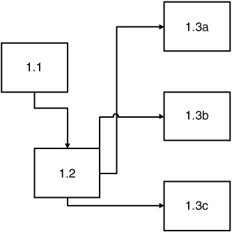
Figure 2.3: A Task Network
DuPont developed the Critical Path Method (CPM) for use in chemical plants. The objective of CPM is to determine the trade-off between project duration and total project cost. This is done by identifying the critical path through activity network. The critical path can help management change the duration of the project. In CPM, an activity time is assumed to be known or predictable.
The Project Evaluation and Review Technique (PERT) was developed by the Navy when designing the Polaris missile. When accurate time estimates are not available, PERT is an ideal tool for project planning because it uses probability theory.
Eventually, CPM and PERT merged into a single technique. Events are shown as nodes and activities are shown as arrows that connect events. Arrows represents the effort required for achieving the next event. Direction specifies the order in which events must occur. There are two types of times for each event. One is the "Earliest Time," the earliest possible time at which the event can be achieved. The other is the "Latest Time," which is the latest time at which the event can occur without delaying subsequent events and completion of the project. For an event, the slack time can be obtained or calculated by the difference between the Latest and the Earliest Times.
The timeline chart (Gantt chart) is generated using automated tools after inputting the task network or task outline and each task's effort, duration, start date, and resource assignment. This chart is very visual and usually the most used part of a project plan. However, it is also possible to create a viable Gantt chart using Microsoft Excel, as shown in Figure 2.4.
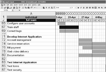
Figure 2.4: Using Excel to Draw a Gantt Chart
Resource Table
This is another output generated by the automated tool, with a focus on the workload for and utilization of the project resources, particularly human resources.
Once a proper project schedule is developed, its tasks and milestones should be tracked and controlled as project proceeds.
Project Resources
An estimation of resources required is an important component of software planning. For each resource, the planner needs to specify the following characteristics: description, a statement of availability, and a time window.
- People. The planner needs to specify the organizational position and specialty of the human resources required by the project. Only after estimating the development effort can one define the number of people required.
- Hardware and software. Hardware and software form the foundation of the software engineering environment [Naur and Randall 1969]. The project planner must determine its time window and verify its availability. Reusable software components should also be specified, alternatives evaluated, and acquisition be made early.
- Training. Special care should be taken to estimate the costs of training ” both initial and ongoing.
- Special resources. Any other resources not covered in the previous sections should be listed here.
- Staff organization. People are the critical factor in a software development effort. In a typical software project, the players fall into five categories: senior managers, project (technical) managers, practitioners , customers, and end users. A good team leader should be able to motivate other players, organize the process, and innovate or encourage people to be creative.
- Team structure (if applicable ). A project manager should decide on the organizational structure for the team. According to Mantei [1981], these three generic team organizations exist: democratic decentralized (DD), controlled decentralized (CD), and controlled centralized (CC). The factors that influence the team structure decision include difficulty of the problem, size of the resultant program(s), team lifetime, problem modularity, criticality of the solution, rigidity of timeline, and communications required. Generally speaking, a DD structure is best for difficult problems, and a CC or CD structure is best for very large projects.
- Management reporting. Coordination and communication issues, including management reporting relationships, should also be addressed here.
Tracking and Control Mechanisms
Errors and changes are inevitable, and one needs to plan ahead to stay prepared when they actually happen.
Quality Assurance and Control
Software quality assurance activities (SQAs) happen at each step of the software process and are carried out by both software engineers and an SQA group . Software engineers assure quality by applying rigorous technical methods and measures, and conducting formal technical reviews and, well-planned testing. The SQA group assists software engineers through a set of activities that address quality assurance planning, over-sight, record keeping, analysis, and reporting. These activities must be planned in this sub-section.
In a CM-based project plan, document verification and continuing performance audit activities should also be included.
Change Management and Control
The later the changes happen in a project, the higher the cost. Change control combines human procedures and automated tools to provide a mechanism for the control of changes that, if uncontrolled, can rapidly lead a large project to chaos. The change control process begins with a change request, leads to a decision to make or reject the request, and culminates with a controlled update of the software configuration item that is to be changed. This part of such activities should be planned here.
In a CM-based system, it is critically important to provide detailed instructions for:
- Identifying changes
- Requesting changes
- Classifying changes
- Documenting requests for changes
- Change impact assessment
- Change approval
Performance Measurement
Metrics should be associated with all software development activities. They should also be associated with configuration management. The purpose of CM metrics is to measure project or program performance. It should be kept in mind that metrics should be reviewed periodically and adjusted for the environment and product life-cycle phase. Typical metrics include:
- Number of configuration documentation releases (scheduled/actual)
- Number of engineering changes (by product, phase, time period)
- Average engineering change cycle time (by product, by classification, by major process step)
- Average revisions per engineering change
- Number of changes
- Number of action items per configuration audit
- Average number of unincorporated changes
Typical software metrics include:
- Lines of code
- Pages of documentation
- Number and size of tests
- Function count
- Variable count
- Number of modules
- Depth of nesting
- Count of changes required
- Count of discovered defects
- Count of changed lines of code
- Time to design, code, test
- Defect discovery rate by phase of development
- Cost to develop
- Number of external interfaces
- Number of tools used and why
- Reusability percentage
- Variance of schedule
- Staff years of experience with team
- Staff years of experience with language
- Software years of experience with software tools
- MIPs per person
- Support-to-development personnel ratio
- Nonproject-to-project time ratio
CONFIGURATION STATUS ACCOUNTING
Configuration management is only as good as the information stored about the project or product. As a result, CM is closely tied to automated tools that correlate, store, maintain, and provide readily available views of configuration data. This includes information about the:
- Configuration documentation (e.g., document identifiers and effective dates)
- Product's configuration (e.g., part numbers )
- Product's operational and maintenance documentation
- CM process (e.g., status of change requests )
SUMMARY
Like any other software engineering task, project planning and writing a detailed project plan take time and cost money. Therefore, a natural question arises: is it worth it? The answer is yes. If one wants a system that is cost effective, does not go over budget, and actually works, then a project plan is mandatory.
More than a few people in this field use the "roadmap" metaphor to describe the role of a project plan; however, it is also a "compass." Its estimation and scheduling part can be likened to a rough roadmap (it can never be precise enough at the beginning of a project), but its risk management, organization plan, tracking, and control parts are definitely a compass. It guides the project team in handling unpredictable risks or undesired events.
A good project plan not only benefits the project itself, but also the domain as whole by its measures and metrics, which can be historical data for other, later projects.
REFERENCES
[Boehm 1981]` Boehm, B., Software Engineering Economics , Prentice Hall, Englewood Cliffs, NJ, 1981 .
[Bounds] Bounds, Nadine and Susan Dart, CM Plans: The Beginning to Your CM Solution. Retrieved from http://www.sei.cmu.edu/legacy/scm/papers/CM_Plans/CMPlans.Chapter3.html#RTFToC1, 2001 .
[EIA 1998] Electronic Industries Alliance, EIA Standard: National Consensus Standard for Configuration Management. EIA-649, Arlington, VA, August 1998 .
[Kerr and Hunter 1994] Kerr, J. and R. Hunter, Inside RAD , McGraw-Hill, New York, 1994 .
[Mantei 1981] Mantei, M., "The Effect of Programming Team Structures on Programming Tasks," Communications of the ACM , 24 (3), 106 “113, March 1981 .
[McDermid and Rook 1993] McDermid, J. and P. Rook, "Software Development Process Models," in Software Engineer's Reference Book , CRC Press, Boca Raton, FL, 1993 , 15/66 “15/28.
[Moder, Phillips, and Davis 1983] Moder, J.J., C.R. Phillips, and E.W. Davis, Project Management with CPM, PERT and Precedence Diagramming , 3rd edition, Van Nostrand Reinhold, New York, 1983 .
[Naur and Randall 1969] Naur, P. and B. Randall, Eds., "Software Engineering: A Report on a Conference Sponsored by the NATO Science Committee," NATO, 1969 .
[Pressman 2001] Pressman, R., Software Engineering, A Practitioner's Approach , 5th edition, McGraw-Hill, New York, 2001 .
[Putman and Myers 1992] Putman, L. and W. Myers, Measures for Excellence , Yourdon Press, 1992 .
[Zahniser 1990] Zahniser, R.A., "Building Software in Groups," American Programmer , 3 (7/8), July/August 1990 .
Preface
- Introduction to Software Configuration Management
- Project Management in a CM Environment
- The DoD CM Process Model
- Configuration Identification
- Configuration Control
- Configuration Status Accounting
- A Practical Approach to Documentation and Configuration Status Accounting
- Configuration Verification and Audit
- A Practical Approach to Configuration Verification and Audit
- Configuration Management and Data Management
- Configuration Change Management
- Configuration Management and Software Engineering Standards Reference
- Metrics and Configuration Management Reference
- CM Automation
- Appendix A Project Plan
- Appendix C Sample Data Dictionary
- Appendix D Problem Change Report
- Appendix E Test Plan
- Appendix G Sample Inspection Plan
- Appendix I System Service Request
- Appendix J Document Change Request (DCR)
- Appendix K Problem/Change Report
- Appendix L Software Requirements Changes
- Appendix M Problem Report (PR)
- Appendix N Corrective Action Processing (CAP)
- Appendix P Project Statement of Work
- Appendix Q Problem Trouble Report (PTR)
- Appendix S Sample Maintenance Plan
- Appendix T Software Configuration Management Plan (SCMP)
- Appendix U Acronyms and Glossary
- Appendix V Functional Configuration Audit (FCA) Checklist
- Appendix W Physical Configuration Audit (PCA) Checklist
- Appendix X SCM Guidance for Achieving the Repeatable Level on the Software
- Appendix Y Supplier CM Market Analysis Questionnaire
EAN: 2147483647
Pages: 235
