The Coordinate System
Understanding the coordinate system is another important part of graphics programming. The coordinate system represents the positions of graphic objects on a display device such as a monitor or a printer.
2.2.1 The Cartesian Coordinate System
The Cartesian coordinate system (shown in Figure 2.2) divides a two-dimensional plane into four regions, also called quadrants, and two axes: x and y. The x-axis is represented by a horizontal line and the y-axis by a vertical line. An ordered pair of x and y positions defines a point in a plane. The origin of the plane is a point with x = 0 and y = 0 values, and the quadrants divide the plane relative to the origin.
Figure 2.2. The Cartesian coordinate system
To find out which point falls in which quadrant, we compare the point's x- and y-positions relative to the origin:
Quadrant I: x > 0 and y > 0
Quadrant II: x < 0 and y > 0
Quadrant III: x < 0 and y < 0
Quadrant IV: x > 0 and y < 0
A point with positive x and y values will fall in quadrant I. A point with +y and x values will fall in quadrant II. A point with x and y values will fall in quadrant III, and a point with +x and y values will fall in quadrant IV. For example, a point at coordinates (2, 3) will fall in quadrant IV, and a point at coordinates (3, 2) will fall in quadrant II.
2.2.2 The Default GDI+ Coordinate System
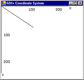
Unlike the Cartesian coordinate system, the default GDI+ coordinate system starts with the origin in the upper left corner. The default x-axis points to the right, and the y-axis points down. As Figure 2.3 shows, the upper left corner starts with points x = 0 and y = 0. Points to the left of x = 0 are negative values in the x-direction, and points above y = 0 are negative values in the y-direction.
Figure 2.3. The GDI+ coordinate system
Because the default GDI+ coordinate system starts with (x = 0, y = 0) in the upper left corner of the screen, by default you can see only the points that have positive x and y values. Objects with either x or y values will not be visible on the screen. However, you can apply transformations to move objects with negative values into the visible area.
GDI+ provides three types of coordinate systems: world coordinates, page coordinates, and device coordinates.
- The coordinate system used in an application is called world coordinates. Suppose that your application draws a line from point A (0, 0) to point B (120, 80), as shown in Figure 2.4. If you don't apply any transformation, the line will be displayed at the right location. Now suppose you want to draw a line from point A (40, 50) to point B (10, 20). The line drawn using these two points will not be displayed on the screen because the GDI+ coordinate system starts at point (0, 0). However, you can transform the coordinates such that (40, 50) is the starting point at the top left corner of the surface.
Figure 2.4. Drawing a line from point (0, 0) to point (120, 80)
- The new coordinate system is called page coordinates. The process of converting world coordinates to page coordinates is called the world transformation.
- You can also control the actual size of graphics objects. For example, if you want to draw a line in inches instead of pixels, you can simply draw a line from point A (1, 1) to point B (1, 2), thereby creating a line that is 1 inch long. The new coordinates are called device coordinates. The process of converting page coordinates to device coordinates is called the page transformation.
We will discuss coordinate systems and transformation in more detail in Chapter 10.
GDI+: The Next-Generation Graphics Interface
- GDI+: The Next-Generation Graphics Interface
- Understanding GDI+
- Exploring GDI+ Functionality
- GDI+ from a GDI Perspective
- GDI+ Namespaces and Classes in .NET
- Summary
Your First GDI+ Application
- Your First GDI+ Application
- Drawing Surfaces
- The Coordinate System
- Tutorial: Your First GDI+ Application
- Some Basic GDI+ Objects
The Graphics Class
- The Graphics Class
- Graphics Class Properties
- Graphics Class Methods
- The GDI+Painter Application
- Drawing a Pie Chart
Working with Brushes and Pens
- Working with Brushes and Pens
- Understanding and Using Brushes
- Using Pens in GDI+
- Transformation with Pens
- Transformation with Brushes
- System Pens and System Brushes
- A Real-World Example: Adding Colors, Pens, and Brushes to the GDI+Painter Application
Colors, Fonts, and Text
- Colors, Fonts, and Text
- Accessing the Graphics Object
- Working with Colors
- Working with Fonts
- Working with Text and Strings
- Rendering Text with Quality and Performance
- Advanced Typography
- A Simple Text Editor
- Transforming Text
Rectangles and Regions
- Rectangles and Regions
- The Rectangle Structure
- The Region Class
- Regions and Clipping
- Clipping Regions Example
- Regions, Nonrectangular Forms, and Controls
Working with Images
- Working with Images
- Raster and Vector Images
- Working with Images
- Manipulating Images
- Playing Animations in GDI+
- Working with Bitmaps
- Working with Icons
- Skewing Images
- Drawing Transparent Graphics Objects
- Viewing Multiple Images
- Using a Picture Box to View Images
- Saving Images with Different Sizes
Advanced Imaging
- Advanced Imaging
- Rendering Partial Bitmaps
- Working with Metafiles
- Color Mapping Using Color Objects
- Image Attributes and the ImageAttributes Class
- Encoder Parameters and Image Formats
Advanced 2D Graphics
- Advanced 2D Graphics
- Line Caps and Line Styles
- Understanding and Using Graphics Paths
- Graphics Containers
- Reading Metadata of Images
- Blending Explained
- Alpha Blending
- Miscellaneous Advanced 2D Topics
Transformation
- Transformation
- Coordinate Systems
- Transformation Types
- The Matrix Class and Transformation
- The Graphics Class and Transformation
- Global, Local, and Composite Transformations
- Image Transformation
- Color Transformation and the Color Matrix
- Matrix Operations in Image Processing
- Text Transformation
- The Significance of Transformation Order
Printing
- Printing
- A Brief History of Printing with Microsoft Windows
- Overview of the Printing Process
- Your First Printing Application
- Printer Settings
- The PrintDocument and Print Events
- Printing Text
- Printing Graphics
- Print Dialogs
- Customizing Page Settings
- Printing Multiple Pages
- Marginal Printing: A Caution
- Getting into the Details: Custom Controlling and the Print Controller
Developing GDI+ Web Applications
- Developing GDI+ Web Applications
- Creating Your First ASP.NET Web Application
- Your First Graphics Web Application
- Drawing Simple Graphics
- Drawing Images on the Web
- Drawing a Line Chart
- Drawing a Pie Chart
GDI+ Best Practices and Performance Techniques
- GDI+ Best Practices and Performance Techniques
- Understanding the Rendering Process
- Double Buffering and Flicker-Free Drawing
- Understanding the SetStyle Method
- The Quality and Performance of Drawing
GDI Interoperability
Miscellaneous GDI+ Examples
- Miscellaneous GDI+ Examples
- Designing Interactive GUI Applications
- Drawing Shaped Forms and Windows Controls
- Adding Copyright Information to a Drawn Image
- Reading and Writing Images to and from a Stream or Database
- Creating Owner-Drawn List Controls
Appendix A. Exception Handling in .NET
