Case Study-Hub and Spoke MPLS VPN Network Using BGP PE-CE Routing for Sites Using Unique AS Numbers
Figure 6-22 shows an MPLS VPN network implementing BGP PE-CE routing in a hub and spoke environment.
Figure 6-22. Hub and Spoke-Based MPLS VPN Network
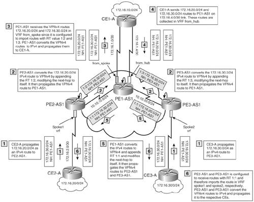
CE1-A, CE2-A, and CE3-A are CE devices. CE1-A is the hub CE for the Customer A network and is connected to PE1-AS1, which is the hub PE router for the Customer A network. CE2-A and CE3-A are spoke sites and are connected to PE2-AS1 and PE3-AS1. As shown in Figure 6-22, the PE-CE link between PE1-AS1 and CE1-A has two links. One link is configured to forward routing information for VRF from_spoke and another link for VRF from_hub. VRF from_spoke on PE1-AS1 is configured to receive routes from spoke sites CE2-A and CE3-A. VRF from_hub receives routes from CE1-A and sends that out to remote sites. The sequence of steps that takes place in the hub and spoke environment is shown in Figure 6-22.
Base MPLS VPN Configuration
Example 6-45 shows the base MPLS configuration.
Example 6-45. Base MPLS VPN Configuration for the Provider Core
hostname PE1-AS1

!

ip cef

!

mpls ldp router-id Loopback0

!

interface Loopback0

 ip address 10.10.10.101 255.255.255.255

!

interface Serial0/0

 ip address 10.10.10.1 255.255.255.252

 mpls ip

!

interface Serial1/0

 ip address 10.10.10.5 255.255.255.252

 mpls ip

!

router ospf 1

 log-adjacency-changes

 network 10.0.0.0 0.255.255.255 area 0

!

router bgp 1

 no synchronization

 bgp log-neighbor-changes

 neighbor 10.10.10.102 remote-as 1

 neighbor 10.10.10.102 update-source Loopback0

 neighbor 10.10.10.103 remote-as 1

 neighbor 10.10.10.103 update-source Loopback0

 no auto-summary

 !

 address-family vpnv4

 neighbor 10.10.10.102 activate

 neighbor 10.10.10.102 send-community extended

 neighbor 10.10.10.103 activate

 neighbor 10.10.10.103 send-community extended

 exit-address-family

__________________________________________________________________________

hostname PE2-AS1

!

ip cef

!

mpls ldp router-id Loopback0

!

interface Loopback0

 ip address 10.10.10.102 255.255.255.255

!

interface Serial0/0

 ip address 10.10.10.2 255.255.255.252

 mpls ip

!

router ospf 1

 log-adjacency-changes

 network 10.0.0.0 0.255.255.255 area 0

!

router bgp 1

 no synchronization

 bgp log-neighbor-changes

 neighbor 10.10.10.101 remote-as 1

 neighbor 10.10.10.101 update-source Loopback0

no auto-summary

!

 address-family vpnv4

 neighbor 10.10.10.101 activate

 neighbor 10.10.10.101 send-community extended

 exit-address-family

__________________________________________________________________________

hostname PE3-AS1

!

ip cef

!

mpls ldp router-id Loopback0

!

interface Loopback0

 ip address 10.10.10.103 255.255.255.255

!

interface Serial0/0

 ip address 10.10.10.6 255.255.255.252

 mpls ip

!

router ospf 1

 log-adjacency-changes

 network 10.0.0.0 0.255.255.255 area 0

!

router bgp 1

 no synchronization

 bgp log-neighbor-changes

 neighbor 10.10.10.101 remote-as 1

 neighbor 10.10.10.101 update-source Loopback0

 no auto-summary

 !

 address-family vpnv4

 neighbor 10.10.10.101 activate

 neighbor 10.10.10.101 send-community extended

 exit-address-family
Hub and Spoke MPLS VPN Configuration for Sites Using Unique AS Numbers
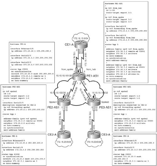
Figure 6-23 shows the relevant configuration to implement hub and spoke MPLS VPN for sites using unique AS numbers.
Figure 6-23. Hub and Spoke MPLS VPN Configuration for Sites Using Unique AS Numbers
Verifying MPLS VPN Hub and Spoke Routing for Sites Using Unique AS Numbers
The steps to verify MPLS VPN hub and spoke routing are
|
Step 1. |
Verify routing on hub PE and spoke PE – Example 6-46 shows that VRF from_spoke on PE1-AS1 has received routes from spoke site Routers CE2-A and CE3-A via the MP-BGP session. VRF from_hub shows the routes received from CE1-A (hub CE). Similarly, PE2-AS1 and PE3-AS1 also show that routes are received by each of the VRFs configured on them. Example 6-46. Verify Routing on Hub PE and Spoke PE Routers PE1-AS1#show ip route vrf from_spoke 172.16.0.0/16 is variably subnetted, 4 subnets, 2 masks B 172.16.30.0/24 [200/0] via 10.10.10.103, 00:24:08 B 172.16.20.0/24 [200/0] via 10.10.10.102, 00:25:08 B 172.16.10.0/24 [20/0] via 172.16.1.2, 00:25:23 C 172.16.1.0/30 is directly connected, Serial2/0 ________________________________________________________________ PE1-AS1#show ip route vrf from_hub 172.16.0.0/16 is variably subnetted, 4 subnets, 2 masks B 172.16.30.0/24 [20/0] via 172.16.1.6, 00:23:58 B 172.16.20.0/24 [20/0] via 172.16.1.6, 00:24:57 B 172.16.10.0/24 [20/0] via 172.16.1.6, 00:27:13 C 172.16.1.4/30 is directly connected, Serial3/0 ________________________________________________________________ PE2-AS1#show ip route vrf spoke1 172.16.0.0/16 is variably subnetted, 4 subnets, 2 masks B 172.16.30.0/24 [200/0] via 10.10.10.101, 00:25:42 B 172.16.20.0/24 [20/0] via 172.16.2.2, 00:26:42 B 172.16.10.0/24 [200/0] via 10.10.10.101, 00:27:27 C 172.16.2.0/30 is directly connected, Serial1/0 ________________________________________________________________ PE3-AS1#show ip route vrf spoke2 172.16.0.0/16 is variably subnetted, 4 subnets, 2 masks B 172.16.30.0/24 [20/0] via 172.16.3.2, 00:34:01 B 172.16.20.0/24 [200/0] via 10.10.10.101, 00:35:02 B 172.16.10.0/24 [200/0] via 10.10.10.101, 00:34:47 C 172.16.3.0/30 is directly connected, Serial1/0 |
|
Step 2. |
Verify routing on CE routers – Example 6-47 shows CE routers have received the relevant BGP routes. Example 6-47. Verify Routing on CE Routers CE1-A#show ip route bgp 172.16.0.0/16 is variably subnetted, 5 subnets, 2 masks B 172.16.30.0/24 [20/0] via 172.16.1.1, 00:29:54 B 172.16.20.0/24 [20/0] via 172.16.1.1, 00:30:56 __________________________________________________________________________ CE1-A#show ip bgp Network Next Hop Metric LocPrf Weight Path *> 172.16.10.0/24 0.0.0.0 0 32768 i *> 172.16.20.0/24 172.16.1.1 0 1 65002 i *> 172.16.30.0/24 172.16.1.1 0 1 65003 i __________________________________________________________________________ CE2-A#show ip route bgp 172.16.0.0/16 is variably subnetted, 4 subnets, 2 masks B 172.16.30.0/24 [20/0] via 172.16.2.1, 00:29:51 B 172.16.10.0/24 [20/0] via 172.16.2.1, 00:31:52 __________________________________________________________________________ CE2-A#show ip bgp Network Next Hop Metric LocPrf Weight Path *> 172.16.10.0/24 172.16.2.1 0 1 65001 i *> 172.16.20.0/24 0.0.0.0 0 32768 i *> 172.16.30.0/24 172.16.2.1 0 1 65001 1 65003 i __________________________________________________________________________ CE3-A#show ip route bgp 172.16.0.0/16 is variably subnetted, 4 subnets, 2 masks B 172.16.20.0/24 [20/0] via 172.16.3.1, 00:31:17 B 172.16.10.0/24 [20/0] via 172.16.3.1, 00:30:46 __________________________________________________________________________ CE3-A#show ip bgp Network Next Hop Metric LocPrf Weight Path *> 172.16.10.0/24 172.16.3.1 0 1 65001 i *> 172.16.20.0/24 172.16.3.1 0 1 65001 1 65002 i *> 172.16.30.0/24 0.0.0.0 0 32768 i |
|
Step 3. |
Verify connectivity between CE routers – Example 6-48 shows CE2-A and CE3-A have access to each other's networks and the 172.16.10.0 network located on CE1-A. Example 6-48. Verify Connectivity Between CE Routers CE2-A#ping 172.16.10.1 source 172.16.20.1 Type escape sequence to abort. Sending 5, 100-byte ICMP Echos to 172.16.10.1, timeout is 2 seconds: Packet sent with a source address of 172.16.20.1 !!!!! Success rate is 100 percent (5/5), round-trip min/avg/max = 60/61/68 ms ___________________________________________________________________________ CE2-A#ping 172.16.30.1 source 172.16.20.1 Type escape sequence to abort. Sending 5, 100-byte ICMP Echos to 172.16.30.1, timeout is 2 seconds: Packet sent with a source address of 172.16.20.1 !!!!! Success rate is 100 percent (5/5), round-trip min/avg/max = 116/119/120 ms ___________________________________________________________________________ CE3-A#ping 172.16.20.1 source 172.16.30.1 Type escape sequence to abort. Sending 5, 100-byte ICMP Echos to 172.16.20.1, timeout is 2 seconds: Packet sent with a source address of 172.16.30.1 !!!!! Success rate is 100 percent (5/5), round-trip min/avg/max = 120/120/120 ms ___________________________________________________________________________ CE3-A#ping 172.16.10.1 source 172.16.30.1 Type escape sequence to abort. Sending 5, 100-byte ICMP Echos to 172.16.10.1, timeout is 2 seconds: Packet sent with a source address of 172.16.30.1 !!!!! Success rate is 100 percent (5/5), round-trip min/avg/max = 48/57/60 ms |
MPLS Overview
- MPLS Overview
- Unicast IP Forwarding in Traditional IP Networks
- Overview of MPLS Forwarding
- MPLS Terminology
- MPLS Control and Data Plane Components
- MPLS Operation
- Special Outgoing Label Types
- Penultimate Hop Popping
- Frame-Mode MPLS
- Cell-Mode MPLS
Basic MPLS Configuration
- Basic MPLS Configuration
- Frame-Mode MPLS Configuration and Verification
- Cell-Mode MPLS over ATM Overview, Configuration, and Verification
- Command Reference
Basic MPLS VPN Overview and Configuration
- Basic MPLS VPN Overview and Configuration
- VPN Categories
- MPLS VPN Architecture and Terminology
- MPLS VPN Routing Model
- MPLS VPN Basic Configuration
- Outbound Route Filters
- Command Reference
PE-CE Routing Protocol-Static and RIP
- PE-CE Routing Protocol-Static and RIP
- Static PE-CE Routing Overview, Configuration, and Verification
- Static PE-CE Routing Command Reference
- RIPv2 PE-CE Routing Overview, Configuration, and Verification
- RIPv1 PE-CE Routing Configuration and Verification
- RIP PE-CE Routing Command Reference
PE-CE Routing Protocol-OSPF and EIGRP
- PE-CE Routing Protocol-OSPF and EIGRP
- OSPF PE-CE Routing Protocol Overview, Configuration and Verification
- EIGRP PE-CE Routing Protocol Overview, Configuration, and Verification
Implementing BGP in MPLS VPNs
- Implementing BGP in MPLS VPNs
- BGP PE-CE Routing Protocol Overview, Configuration, and Verification
- Implementing Route-Reflectors in MPLS VPN Networks
- Case Study-Hub and Spoke MPLS VPN Network Using BGP PE-CE Routing for Sites Using Unique AS Numbers
- Case Study-Hub and Spoke MPLS VPN Network with Sites Using Same AS Numbers
- Command Reference
Inter-Provider VPNs
- Inter-Provider VPNs
- Overview of Inter-Provider VPNs
- Option 1: Inter-Provider VPN Using Back-to-Back VRF Method
- Option 2: Inter-Provider VPNs Using ASBR-to-ASBR Approach
- Option 3: Multi-Hop MP-eBGP Between RR and eBGP Between ASBRs
- Option 4: Non-VPN Transit Provider
- Case Study-Inter-AS Implementing Route-Reflector and BGP Confederation in Provider Networks
- Case Study-Multi-Homed Inter-AS Provider Network
- Command Reference
Carrier Supporting Carriers
- Carrier Supporting Carriers
- Carrier Supporting Carriers Overview
- Deployment Scenarios with CSC Architecture
- CSC Architecture Benefits
- Command Reference
MPLS Traffic Engineering
- MPLS Traffic Engineering
- TE Basics
- MPLS TE Theory
- Constraint-Based Routing and Operation in MPLS TE
- Configuring MPLS TE
- Command Reference
Implementing VPNs with Layer 2 Tunneling Protocol Version 3
- Implementing VPNs with Layer 2 Tunneling Protocol Version 3
- L2TPv3 Overview
- Configuring L2TPv3 Tunnels for Layer 2 VPN
- Configuring L2TPv3 Static Tunnels
- Configuring L2TPv3 Dynamic Tunnels
- Implementing Layer 3 VPNs over L2TPv3 Tunnels
- Command Reference
Any Transport over MPLS (AToM)
- Any Transport over MPLS (AToM)
- Introduction to Layer 2 VPNs
- Implementing AToM for Like to Like Circuits
- L2 VPN-Any to Any Interworking
- Local Switching
- Command Reference
Virtual Private LAN Service (VPLS)
- Virtual Private LAN Service (VPLS)
- VPLS Overview
- VPLS Topology-Single PE or Direct Attachment
- Hierarchical VPLS-Distributed PE Architecture
- Command Reference
Implementing Quality of Service in MPLS Networks
- Implementing Quality of Service in MPLS Networks
- Introduction to QoS-Classification and Marking
- MPLS QoS Implementation
- MPLS QoS Operating Modes
- Modular QoS CLI: Configuration of QoS on Cisco Routers
- Configuration and Implementation of MPLS QoS in Uniform Mode and Short Pipe Mode Operation
- Implementing MPLS QoS for Layer 2 VPN Implementations
- Command Reference
MPLS Features and Case Studies
- MPLS Features and Case Studies
- Case Study 1: Implementing Multicast Support for MPLS VPNs
- Case Study 2: Implementing Multi-VRF CE, VRF Selection Using Source IP Address, VRF Selection Using Policy-Based Routing, NAT and HSRP Support in MPLS VPN, and Multicast VPN Support over Multi-VRF CE
- Case Study 3: Implementing Layer 2 VPNs over Inter-AS Topologies Using Layer 2 VPN Pseudo-Wire Switching
- Case Study 4: Implementing Layer 3 VPNs over Layer 2 VPN Topologies and Providing L2 VPN Redundancy
- Case Study 5: Implementing Dynamic Layer 3 VPNs Using mGRE Tunnels
- Case Study 6: Implementing Class-Based Tunnel Selection with MPLS Traffic Engineering
- Case Study 7: Implementing Hub and Spoke Topologies with OSPF
- Case Study 8: Implementing Hub and Spoke Topologies with EIGRP
- Case Study 9: Implementing VPLS Services with the GSR 12000 Series
- Case Study 10: BGP Site of Origin
- Command Reference
EAN: 2147483647
Pages: 130
