VPLS Overview
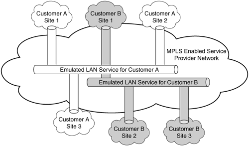
VPLS allows multiple Ethernet LANs from different customer sites to be connected together across the service provider (SP) network, thereby emulating a single Ethernet LAN segment for that customer. Figure 12-1 shows an SP network providing VPLS services in which multiple customer sites (belonging to Customer A) can communicate as if they are connected as a private Ethernet LAN segment. VPLS uses Multiprotocol Label Switching (MPLS) to offer multipoint Ethernet connectivity over a mesh of logical circuits or tunnels, with the added benefits of Traffic Engineering (TE), resilience, and failover. VPLS enables carriers and SPs to offer managed Ethernet VPN services easily and cost effectively.
Figure 12-1. VPLS – Emulated LAN Service
VPLS Components
The six components that are part of VPLS are as follows:
- Attachment circuit – A point-to-point, Layer 2 circuit between a CE router at the customer site to the connected provider edge (PE) router in the provider network. In VPLS, the currently supported attachment circuits are Ethernet in
- Port mode – In port mode, the interface only sends and accepts untagged Ethernet packets.
- 802.1Q VLAN or trunk mode – In this mode, the interface is configured as 802.1Q trunk, and it sends and receives only tagged Ethernet VLAN and native VLAN packets.
- Dot1q tunnel mode – In this mode, an 802.1Q tunnel is configured and an access VLAN tag is added to the packet at the ingress tunnel interface and removed at the egress tunnel interface. Packets irrespective of being tagged or untagged are forwarded through the 802.1Q tunnel.
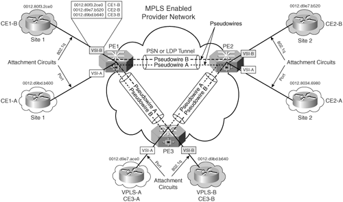
Figure 12-2 depicts attachment circuits for Customer A and Customer B VPLS networks that function in Ethernet port mode (Customer A) and 802.1Q mode (Customer B).
- Packet Switched Network (PSN) tunnels – PSN tunnels are built between two PE devices in a PSN to provide transport services for one or more pseudo wires (emulated VCs). In VPLS architecture, the transport is provided over MPLS label switch path (LSP).
- Pseudo wires – A pseudo wire is an emulated virtual circuit that connects two attachment circuits (AC) on two different PE routers across an MPLS-enabled provider network. Figure 12-2 shows the pseudo wire between the PE routers, PE1, PE2, and PE3 for Customer A CE sites.
- Auto-discovery – Auto-discovery is a mechanism that enables multiple PE routers participating in a VPLS domain to find each other. Auto-discovery, as a result, automates the creation of the LSP mesh. In the absence of auto-discovery, the SP must explicitly identify PEs that are part of a VPLS instance. Therefore, for every VPLS instance on a PE, the SP would have to configure the PE with addresses of all other PEs in that VPLS instance.
- Auto configuration – Auto configuration is a mechanism that automatically establishes pseudo wires (emulated VCs) for newly discovered CEs.
- Virtual Switching Instance (VSI) or Virtual Forwarding Instance (VFI) – The VSI or VFI is a virtual Layer 2 forwarding entity that defines the VPLS domain membership and resembles virtual switches on PE routers. A VPLS domain consists of Ethernet interfaces or VLANs that belong to the same (virtual) LAN but are connected to multiple PE devices. For example, Customer A's VPLS domain consists of Ethernet interfaces connected to Customer A's CE routers at different sites. The VSI learns remote MAC addresses and is responsible for proper forwarding of the customer traffic to the appropriate end nodes. It is also responsible for guaranteeing that each VPLS domain is loop free. The VSI is responsible for several functions, namely MAC address management, dynamic learning of MAC addresses on physical ports and VCs, aging of MAC addresses, MAC address withdrawal, flooding, and data forwarding.
Figure 12-2. VPLS Components
VPLS Operation
VPLS provides an Ethernet multipoint service and typically would involve the following:
- MAC address learning
- MAC address withdrawal
MAC Address Learning
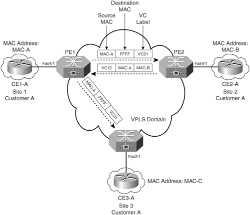
Using a directed LDP session, each PE advertises a VC label mapping that is used as part of the label stack imposed on the Ethernet frames by the ingress PE during packet forwarding. Cisco VPLS learns MAC addresses by using the standard 802.1d (spanning tree) mechanism to learn, age, and filter MAC addresses. Figure 12-3 shows an MPLS-enabled provider network delivering VPLS service to Customer A sites.
Figure 12-3. MAC Address Learning
The VPLS network for Customer A is a full mesh of Ethernet pseudo wires. The VPLS instance per customer is assigned a unique Virtual Circuit Identifier (VCI). The emulated VC formed between the PE routers consists of bidirectional LSPs. MAC addresses are learned via the directed LDP label mappings between the PE routers:
- PE1 and PE2 have IGP reachability and can communicate via the LSP tunnel. As shown in Figure 12-3, PE1 allocates a local Label VC12 for its attached circuit, and this label is propagated to PE2. PE2 allocates Label VC21 and sends this VC label to PE1.
- A packet from CE1-A destined for CE2-A requires knowledge of the CE2-A MAC address, MAC-B. PE1 and PE2 do not have the information on the location of MAC-B (CE2-A) and MAC-A (CE1-A). Therefore, when the packet leaves CE1-A, the source MAC address is MAC-A, and, because CE1-A does not have knowledge of CE2-A (MAC-B), a broadcast is sent and relayed by PE1 to PE2 and PE3. As shown in Figure 12-4, PE1 sends a broadcast packet with the source MAC address of CE1-A (MAC-A) to other peers PE2 and PE3 in the VPLS domain. This broadcast packet is sent with the VC Label VC21 to PE2, which was learned from PE2 during the formation of the directed LDP session between PE1 and PE2. Similarly, this broadcast packet is also sent with VC Label VC31 to PE3.
- PE2 receives the packet from PE1 and associates the source MAC address MAC-A with the inner label (VC label) VC21 and, therefore, concludes that the source MAC address MAC-A is behind PE1 network. Because VC21 was initially assigned and propagated by PE2 to PE1 during the directed LDP session establishment, PE2 can now associate MAC-A with VC21.
Figure 12-4. VPLS Network Without MAC Address Withdrawal Process
As described previously, MAC address learning is done based on the traffic monitoring of customer Ethernet frames. The Forwarding Information Base (FIB) keeps track of the mapping of customer MAC addresses and their associated pseudo wires (VC labels). There are two modes of the MAC address learning process: unqualified and qualified.
In unqualified learning, all customer VLANs are handled by a single VSI, essentially sharing a single broadcast domain and MAC address space. This implies that MAC addresses need to be unique and nonoverlapping among customer VLANs; otherwise, they cannot be differentiated within the VSI, which can result in loss of customer frames. An application of unqualified learning is port-based VPLS service for a given customer (for example, where the all traffic received over the CE-PE interface is mapped to a single VSI).
In qualified learning, each customer VLAN is assigned its own VSI, which means each customer VLAN has its own broadcast domain and MAC address space. Therefore, in qualified learning, MAC addresses among customer VLANs may overlap with each other, but will be handled correctly because each customer VLAN has its own FIB (i.e., each customer VLAN has its own MAC address space). Because VSI broadcasts multicast frames, qualified learning offers the advantage of limiting the broadcast scope to a given customer VLAN.
MAC Address Withdrawal
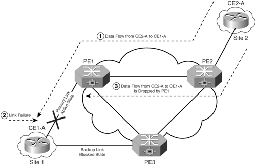
MAC address withdrawal occurs during failure of the PE to CE link or when the CE is dual-homed to two different PE routers and the primary link fails. Figure 12-4 shows an example in which the CE is multihomed to a SP and connected via a primary and backup link to different PE routers.
In the absence of the MAC address withdrawal process, the following sequence of events takes place:
|
1. |
CE2-A sends traffic to CE1-A. |
|
2. |
During this process, the primary link fails, and the traffic flow to CE1-A is still being forwarded to PE1 until the entry in the FIB ages out. |
|
3. |
The primary PE router PE1 would, however, drop the traffic because the link between PE1 and CE1-A is not operational. |
To avoid this situation, an optional MAC Type-Length-Value (TLV) is used to specify a list of MAC addresses that can be removed or relearned, and it is included in the LDP Address Withdraw message. The MAC TLV is an optional TLV and expedites removal of MAC addresses as the result of a topology change when there is a link failure between CE1-A and PE1.
Figure 12-5 shows that PE1 removes any locally learned MAC addresses on failure of the primary link and sends an LDP Withdraw message to remote PEs in the VPLS.
Figure 12-5. With MAC Address Withdrawal Process
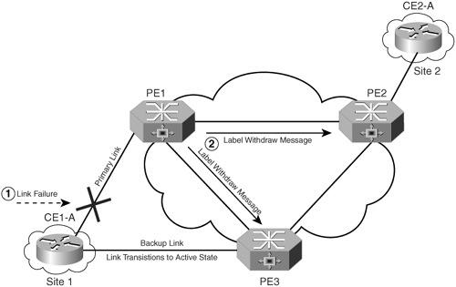
If a notification message with a list of MAC entries to be relearned is sent on the backup (blocked) link, which has transitioned into an active state (e.g., similar to the Topology Change Notification message of 802.1w Rapid STP), the PE will update the MAC entries in its FIB for that VSI and send the LDP Address Withdraw message to other PEs over the corresponding directed LDP sessions.
If the message contains an empty list, the receiving PE removes all the MAC addresses learned for the specified VSI except those learned from the sending PE (MAC address removal is required for all VSI instances that are affected). This mechanism guarantees consistency in MAC address withdrawal under all circumstances.
MPLS Overview
- MPLS Overview
- Unicast IP Forwarding in Traditional IP Networks
- Overview of MPLS Forwarding
- MPLS Terminology
- MPLS Control and Data Plane Components
- MPLS Operation
- Special Outgoing Label Types
- Penultimate Hop Popping
- Frame-Mode MPLS
- Cell-Mode MPLS
Basic MPLS Configuration
- Basic MPLS Configuration
- Frame-Mode MPLS Configuration and Verification
- Cell-Mode MPLS over ATM Overview, Configuration, and Verification
- Command Reference
Basic MPLS VPN Overview and Configuration
- Basic MPLS VPN Overview and Configuration
- VPN Categories
- MPLS VPN Architecture and Terminology
- MPLS VPN Routing Model
- MPLS VPN Basic Configuration
- Outbound Route Filters
- Command Reference
PE-CE Routing Protocol-Static and RIP
- PE-CE Routing Protocol-Static and RIP
- Static PE-CE Routing Overview, Configuration, and Verification
- Static PE-CE Routing Command Reference
- RIPv2 PE-CE Routing Overview, Configuration, and Verification
- RIPv1 PE-CE Routing Configuration and Verification
- RIP PE-CE Routing Command Reference
PE-CE Routing Protocol-OSPF and EIGRP
- PE-CE Routing Protocol-OSPF and EIGRP
- OSPF PE-CE Routing Protocol Overview, Configuration and Verification
- EIGRP PE-CE Routing Protocol Overview, Configuration, and Verification
Implementing BGP in MPLS VPNs
- Implementing BGP in MPLS VPNs
- BGP PE-CE Routing Protocol Overview, Configuration, and Verification
- Implementing Route-Reflectors in MPLS VPN Networks
- Case Study-Hub and Spoke MPLS VPN Network Using BGP PE-CE Routing for Sites Using Unique AS Numbers
- Case Study-Hub and Spoke MPLS VPN Network with Sites Using Same AS Numbers
- Command Reference
Inter-Provider VPNs
- Inter-Provider VPNs
- Overview of Inter-Provider VPNs
- Option 1: Inter-Provider VPN Using Back-to-Back VRF Method
- Option 2: Inter-Provider VPNs Using ASBR-to-ASBR Approach
- Option 3: Multi-Hop MP-eBGP Between RR and eBGP Between ASBRs
- Option 4: Non-VPN Transit Provider
- Case Study-Inter-AS Implementing Route-Reflector and BGP Confederation in Provider Networks
- Case Study-Multi-Homed Inter-AS Provider Network
- Command Reference
Carrier Supporting Carriers
- Carrier Supporting Carriers
- Carrier Supporting Carriers Overview
- Deployment Scenarios with CSC Architecture
- CSC Architecture Benefits
- Command Reference
MPLS Traffic Engineering
- MPLS Traffic Engineering
- TE Basics
- MPLS TE Theory
- Constraint-Based Routing and Operation in MPLS TE
- Configuring MPLS TE
- Command Reference
Implementing VPNs with Layer 2 Tunneling Protocol Version 3
- Implementing VPNs with Layer 2 Tunneling Protocol Version 3
- L2TPv3 Overview
- Configuring L2TPv3 Tunnels for Layer 2 VPN
- Configuring L2TPv3 Static Tunnels
- Configuring L2TPv3 Dynamic Tunnels
- Implementing Layer 3 VPNs over L2TPv3 Tunnels
- Command Reference
Any Transport over MPLS (AToM)
- Any Transport over MPLS (AToM)
- Introduction to Layer 2 VPNs
- Implementing AToM for Like to Like Circuits
- L2 VPN-Any to Any Interworking
- Local Switching
- Command Reference
Virtual Private LAN Service (VPLS)
- Virtual Private LAN Service (VPLS)
- VPLS Overview
- VPLS Topology-Single PE or Direct Attachment
- Hierarchical VPLS-Distributed PE Architecture
- Command Reference
Implementing Quality of Service in MPLS Networks
- Implementing Quality of Service in MPLS Networks
- Introduction to QoS-Classification and Marking
- MPLS QoS Implementation
- MPLS QoS Operating Modes
- Modular QoS CLI: Configuration of QoS on Cisco Routers
- Configuration and Implementation of MPLS QoS in Uniform Mode and Short Pipe Mode Operation
- Implementing MPLS QoS for Layer 2 VPN Implementations
- Command Reference
MPLS Features and Case Studies
- MPLS Features and Case Studies
- Case Study 1: Implementing Multicast Support for MPLS VPNs
- Case Study 2: Implementing Multi-VRF CE, VRF Selection Using Source IP Address, VRF Selection Using Policy-Based Routing, NAT and HSRP Support in MPLS VPN, and Multicast VPN Support over Multi-VRF CE
- Case Study 3: Implementing Layer 2 VPNs over Inter-AS Topologies Using Layer 2 VPN Pseudo-Wire Switching
- Case Study 4: Implementing Layer 3 VPNs over Layer 2 VPN Topologies and Providing L2 VPN Redundancy
- Case Study 5: Implementing Dynamic Layer 3 VPNs Using mGRE Tunnels
- Case Study 6: Implementing Class-Based Tunnel Selection with MPLS Traffic Engineering
- Case Study 7: Implementing Hub and Spoke Topologies with OSPF
- Case Study 8: Implementing Hub and Spoke Topologies with EIGRP
- Case Study 9: Implementing VPLS Services with the GSR 12000 Series
- Case Study 10: BGP Site of Origin
- Command Reference
EAN: 2147483647
Pages: 130
