Scenario 4-9: Improving Convergence and Load Sharing by Using a Multilayer Topology
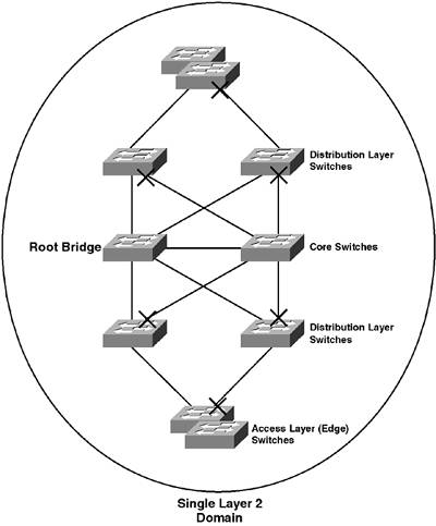
| Many of the convergence and load sharing limitations of spanning tree can be overcome by implementing a multilayer switch design, rather than a straight Layer 2 topology. Figure 4-31 shows a complex network topology, which is designed as a Layer 2 topology. Figure 4-31. Layer 2 Topology
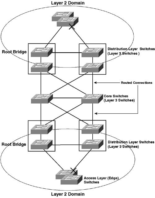
In Figure 4-31, the Layer 2 topology has been designed so that access layer switches can still connect to the rest of the network in the event of a single core or distribution switch failure. The STP topology for a single VLAN is shown, with blocked ports indicated. The topology has a network diameter of 5, which means that STP timers cannot be lowered significantly to reduce convergence. A different STP topology is required for other VLANs if load sharing is required. Although different STP topologies can be present in Figure 4-31, the network topology is a single Layer 2 domain. UplinkFast can be implemented at the edge of the network to reduce convergence for access layer switches in the event of a direct failure, and BackboneFast can be enabled to reduce the convergence for all switches if an indirect failure occurs. Even with these enhancements, the topology is complex and difficult to both configure and maintain. Figure 4-32 demonstrates a multilayer equivalent topology for the Layer 2 topology shown in Figure 4-31. Figure 4-32. Multilayer Topology
In Figure 4-32, all core and distribution switches are Layer 3 switches. Notice that each distribution switch is illustrated with the internal logical switch and router components that combine to make a Layer 3 switch. Each distribution layer switch has a routing component that terminates the Layer 2 domain that all of the access layer switches reside in, making the spanning-tree topology within the Layer 2 domain much simpler. All connections between the distribution layer switches and the core switches are routed connections, so no spanning-tree topology is present. There is essentially a single Layer 2 domain per redundant pair of distribution layer switches. The active spanning-tree topology within these Layer 2 domains is configured so that both uplinks from the access layer switches are active. UplinkFast is enabled on each access layer switch, which ensures the convergence related to a direct failure is limited to a few seconds. If a distribution layer switch fails, UplinkFast ensures convergence is in a matter of seconds. The STP topology for each Layer 2 domain is very simple, and spanning-tree timers can be significantly reduced within each Layer 2 domain, as the network diameter is significantly smaller. From a Layer 3 perspective, at the edge of the network, the distribution layer switches are configured with Hot Standby Routing Protocol (HSRP), with one distribution layer switch acting as the active default gateway for a VLAN and the other acting as a backup default gateway. The active role is spread between the two switches for each VLAN. If a distribution layer switch is the root bridge for a VLAN, then it is also the primary default gateway for the VLAN, which ensures the IP traffic flow matches the active STP topology for each VLAN. Within the core and distribution-to-core portions of the network, no spanning tree topology is in place, meaning all load sharing and redundancy is handled by Layer 3 routing protocols, which are much better at implementing these features than spanning tree. NOTE Don't worry if you don't fully understand the concepts discussed in Figure 4-32; they are discussed further in Chapter 5, "Inter-VLAN Routing" and Chapter 6, "Layer 3 Switching." |
EAN: 2147483647
Pages: 135