Rapid Dialog Design
Qt is designed to be pleasant and intuitive to hand-code, and it is perfectly possible to develop Qt applications purely by writing C++ source code. Qt Designer expands the options available to programmers, allowing them to combine visually designed forms with their source code.
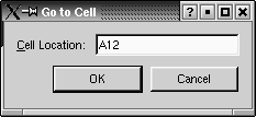
In this section, we will use Qt Designer to create the Go-to-Cell dialog shown in Figure 2.4. Whether we do it in code or in Qt Designer, creating a dialog always involves the same fundamental steps:
- Create and initialize the child widgets.
- Put the child widgets in layouts.
- Set the tab order.
- Establish signalslot connections.
- Implement the dialog's custom slots.
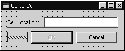
Figure 2.4. Go-to-Cell dialog
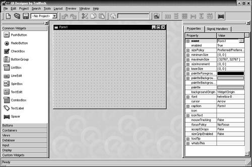
To launch Qt Designer, click Qt 3.2.x|Qt Designer in the Start menu on Windows, type designer on the command line on Unix, or double-click designer in the Mac OS X Finder. When Qt Designer starts, it will pop up a list of templates. Click the "Dialog" template, then click OK. You should now have a window called "Form1".
Figure 2.5. Qt Designer with an empty form
The first step is to create the child widgets and place them on the form. Create one text label, one line editor, one (horizontal) spacer, and two push buttons. For each item, click its name or icon in the "toolbox" at the left of Qt Designer's main window and then click the form roughly where the item should go. Now drag the bottom of the form up to make it shorter. This should produce a form that is similar to Figure 2.6. Don't spend too much time positioning the items on the form; Qt's layout managers will lay them out precisely later on.
Figure 2.6. The form with some widgets
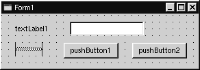
The spacer item is shown in Qt Designer as a blue spring. It is invisible in the final form.
Set each widget's properties using the property editor on the right of Qt Designer's main window:
- Click the text label. Set its name property to "label" and its text property to "&Cell Location:".
- Click the line editor. Set its name property to "lineEdit".
- Click the spacer. Make sure that the spacer's orientation property is set to "Horizontal".
- Click the first button. Set its name property to "okButton", its enabled property to "False", its default property to "True", and its text property to "OK".
- Click the second button. Set its name property to "cancelButton" and its text property to "Cancel".
- Click the background of the form to select the form itself. Set its name property to "GoToCellDialog" and its caption property to "Go to Cell".
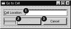
All the widgets look fine now, except the text label, which shows &Cell Location. Click Tools|Set Buddy. Click the label and drag the rubber band to the line editor, then release. The label should now show Cell Location and have the line editor as its buddy. You can verify this by checking that the label's buddy property is set to "lineEdit".
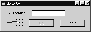
Figure 2.7. The form with properties set
The next step is to lay out the widgets on the form:
- Click the Cell Location label and press Shift as you click the line editor next to it so that they are both selected. Click Layout|Lay Out Horizontally.
- Click the spacer, then hold Shift as you click the form's OK and Cancel buttons. Click Layout|Lay Out Horizontally.
- Click the background of the form to deselect any selected items, then click Layout|Lay Out Vertically.
- Click Layout|Adjust Size to resize the form to its optimal size.
The red lines that appear on the form show the layouts that have been created. They never appear when the form is run.
Figure 2.8. The form with the layouts
Now click Tools|Tab Order. A number in a blue circle will appear next to every widget that can accept focus. Click each widget in turn in the order you want them to accept focus, then press Esc.
Figure 2.9. Setting the form's tab order
Now that the form has been designed, we are ready to make it functional by setting up some signalslot connections and by implementing some custom slots. Click Edit|Connections to invoke the connection editor.
Figure 2.10. Qt Designer's connection editor (after making the connections)
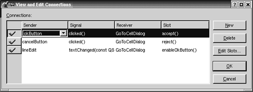
We need to establish three connections. To create a connection, click New and set the Sender, Signal, Receiver, and Slot fields using the drop-down comboboxes.
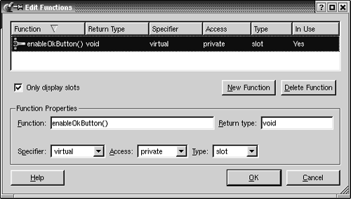
Connect the okButton's clicked() signal to the GoToCellDialog's accept() slot. Connect the cancelButton's clicked() signal to the GoToCellDialog's reject() slot. Click Edit Slots to invoke Qt Designer's slot editor (shown in Figure 2.11), and create an enableOkButton() private slot. Finally, connect the lineEdit's textChanged(const QString &) signal to the GoToCellDialog's new enableOkButton() slot.
Figure 2.11. Qt Designer's slot editor
To preview the dialog, click the Preview|Preview Form menu option. Check the tab order by pressing Tab repeatedly. Press Alt+C to move the focus to the line editor. Click Cancel to close the dialog.
Save the dialog as gotocelldialog.ui in a directory called gotocell, and create a main.cpp file in the same directory using a plain text editor:
#include

#include "gotocelldialog.h"

int main(int argc, char *argv[])
{
 QApplication app(argc, argv);
 GoToCellDialog *dialog = new GoToCellDialog;
 app.setMainWidget(dialog);
 dialog->show();
 return app.exec();
}
Now run qmake to create a .pro file and a makefile (qmake -project; qmake gotocell.pro). The qmake tool is smart enough to detect the user interface file gotocelldialog.ui and to generate the appropriate makefile rules to create gotocelldialog.h and gotocelldialog.cpp. The .ui file is converted to C++ by uic, Qt's user interface compiler.
One of the beauties of using Qt Designer is that it allows programmers great freedom to modify their form designs without disturbing their source code. When you develop a form purely by writing C++ code, changes to the design can be quite time-consuming. With Qt Designer, no time is lost since uic simply regenerates the source code for any forms that have changed.
If you run the program now, the dialog will work, but it doesn't function exactly as we want:
- The OK button is always disabled.
- The line editor accepts any text, instead of only accepting valid cell locations.
We must write some code to solve these problems.
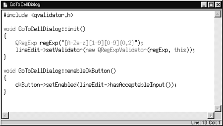
Double-click the background of the form to invoke Qt Designer's code editor. In the editor window, enter the following code:
#include

void GoToCellDialog::init()
{
 QRegExp regExp("[AZaz] [19] [09] {0, 2}");
 lineEdit->setValidator(new QRegExpValidator(regExp, this));
}

void GoToCellDialog::enableOkButton()
{
 okButton->setEnabled(lineEdit->hasAcceptableInput());
}
The init() function is automatically called at the end of the form's constructor (generated by uic). We set up a validator to restrict the range of the input. Qt provides three built-in validator classes: QIntValidator, QDoubleValidator, and QRegExpValidator. Here we use a QRegExpValidator with the regular expression "[A-Za-z][1-9][0-9]{0,2}", which means: Allow one upper or lower-case letter, followed by one digit in the range 1 to 9, followed by up to two digits each in the range 0 to 9. (For an introduction to regular expressions, see the QRegExp class documentation.)
By passing this to the QRegExpValidator constructor, we make it a child of the GoToCellDialog object. By doing so, we don't have to worry about deleting the QRegExpValidator later; it will be deleted automatically when its parent is deleted.
The enableOkButton() slot enables or disables the OK button, according to whether the line edit contains a valid cell location. QLineEdit::hasAcceptableInput() uses the validator we set in the init() function.
Figure 2.12. Qt Designer's code editor
After typing the code, save the dialog again. This will effectively save two files: the user interface file gotocelldialog.ui, and the C++ source file gotocelldialog.ui.h. Make the application once more and run it again. Type "A12" in the line edit, and notice that the OK button becomes enabled. Try typing some random text to see how the validator does its job. Click Cancel to close the dialog.
In this example, we edited the dialog in Qt Designer, then we added some code using Qt Designer's code editor. The dialog's user interface is saved in a .ui file (an XML-based file format), while the code is saved in a .ui.h file (a C++ source file). This split is very convenient for developers who want to edit the .ui.h file in their favorite text editor.
An alternative to the .ui.h approach is to create a .ui file with Qt Designer as usual, then create an additional class that inherits the uic-generated class and adds the extra functionality there. For example, for the Go-to-Cell dialog, this would mean creating a GoToCellDialogImpl class that inherits GoToCellDialog and that implements what's missing. It is straightforward to convert the .ui.h code to use this approach. The result is this header file:
#ifndef GOTOCELLDIALOGIMPL_H
#define GOTOCELLDIALOGIMPL_H

#include "gotocelldialog.h"

class GoToCellDialogImpl : public GoToCellDialog
{
 Q_OBJECT
public:
 GoToCellDialogImpl(QWidget *parent = 0, const char *name = 0);

private slots:
 void enableOkButton();
};

#endif
And this source file:
#include
#include
#include

#include "gotocelldialogimpl.h"

GoToCellDialogImpl::GoToCellDialogImpl(QWidget *parent,
 const char *name)
 : GoToCellDialog(parent, name)
{
 QRegExp regExp("[A-Za-z][1-9][0-9]{0,2}");
 lineEdit->setValidator(new QRegExpValidator(regExp, this));
}

void GoToCellDialogImpl::enableOkButton()
{
 okButton->setEnabled(lineEdit->hasAcceptableInput());
}
Developers who prefer the subclassing approach would probably call the base class GoToCellDialogBase and the derived class GoToCellDialog, keeping the better name for the class that contains all the functionality.
The uic tool provides command-line options to simplify the creation of subclasses based on forms created with Qt Designer. Use subdecl to generate a skeleton header file, and use subimpl to generate the matching implementation file.
In this book, we use the .ui.h approach since this is the most common practice, and since it is easy to convert .ui.h files into subclasses. You might want to read the "Designer Approach" chapter in Qt Designer's manual for a technical appreciation of the differences between subclassing and using .ui.h files. Another chapter in the manual, "Creating Dialogs", demonstrates how to use Qt Designer's Members tab to declare member variables in uic- generated classes.
Part I: Basic Qt
Getting Started
Creating Dialogs
- Creating Dialogs
- Subclassing QDialog
- Signals and Slots in Depth
- Rapid Dialog Design
- Shape-Changing Dialogs
- Dynamic Dialogs
- Built-in Widget and Dialog Classes
Creating Main Windows
- Creating Main Windows
- Subclassing QMainWindow
- Creating Menus and Toolbars
- Implementing the File Menu
- Setting Up the Status Bar
- Using Dialogs
- Storing Settings
- Multiple Documents
- Splash Screens
Implementing Application Functionality
- Implementing Application Functionality
- The Central Widget
- Subclassing QTable
- Loading and Saving
- Implementing the Edit Menu
- Implementing the Other Menus
- Subclassing QTableItem
Creating Custom Widgets
- Creating Custom Widgets
- Customizing Qt Widgets
- Subclassing QWidget
- Integrating Custom Widgets with Qt Designer
- Double Buffering
Part II: Intermediate Qt
Layout Management
- Layout Management
- Basic Layouts
- Splitters
- Widget Stacks
- Scroll Views
- Dock Windows
- Multiple Document Interface
Event Processing
- Event Processing
- Reimplementing Event Handlers
- Installing Event Filters
- Staying Responsive During Intensive Processing
2D and 3D Graphics
Drag and Drop
Input/Output
- Input/Output
- Reading and Writing Binary Data
- Reading and Writing Text
- Handling Files and Directories
- Inter-Process Communication
Container Classes
Databases
Networking
XML
Internationalization
- Internationalization
- Working with Unicode
- Making Applications Translation-Aware
- Dynamic Language Switching
- Translating Applications
Providing Online Help
- Providing Online Help
- Tooltips, Status Tips, and Whats This? Help
- Using QTextBrowser as a Simple Help Engine
- Using Qt Assistant for Powerful Online Help
Multithreading
- Multithreading
- Working with Threads
- Communicating with the GUI Thread
- Using Qts Classes in Non-GUI Threads
Platform-Specific Features
EAN: 2147483647
Pages: 140
