OSPF PE-CE Routing Protocol Overview, Configuration and Verification
Open Shortest Path First (OSPF) PE-CE routing protocol support was developed for service providers offering MPLS VPN services to customers who have deployed OSPF as their intra-site routing protocol and, hence, preferred usage of OSPF as the VPN inter-site routing protocol in an MPLS VPN environment. Forthcoming sections introduce you to the issues with implementing traditional OSPF routing models in MPLS VPN environments and the concept of the OSPF superbackbone to resolve them. In addition, the OSPF PE-CE routing configuration in an MPLS VPN environment and OSPF sham-links, used to resolve suboptimal routing caused by backdoor links between OSPF sites in MPLS VPN environments, are discussed.
Traditional OSPF Routing Model
The traditional OSPF domain is divided into backbone (Area 0) and non-backbone areas where non-backbone areas are connected to Area 0. Figure 5-1 shows Customer A implementing the traditional OSPF model in which non-backbone areas, Area 1 and Area 2 belonging to Site 1 and Site 2, respectively, are connected to the OSPF backbone area, Area 0.
Figure 5-1. Traditional OSPF and MPLS VPN Routing Model
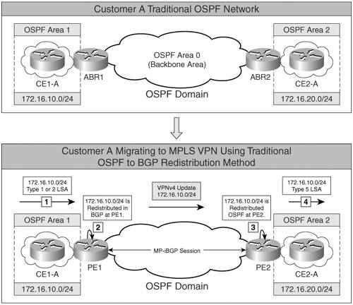
In an MPLS VPN environment, customer networks are connected to an MPLS VPN-enabled provider backbone. As shown in Figure 5-1, Customer A areas, Areas 1 and 2, are now connected to an MPLS VPNenabled provider network. Area 1 and Area 2 have routers CE1-A and CE2-A running OSPF routing protocol. MP-iBGP is used between PE1 and PE2 to propagate routes between Site 1 (Area 1) and Site 2 (Area 2). Traditional OSPF-BGP redistribution is performed at PE routers, PE1 and PE2. Figure 5-1 depicts the following sequence that takes place in traditional OSPF-BGP redistribution:
- Network 172.16.10.0/24 is advertised to the PE1 router by CE1-A as a Type 1 or Type 2 link-state advertisement (LSA).
- Traditional OSPF-BGP route redistribution takes place where 172.16.10.0/24 is redistributed into BGP at PE1. This route is then propagated as a VPNv4 route to PE2.
- At PE2, the BGP VPNv4 prefix 172.16.10.0/24 is redistributed in OSPF.
- This redistributed route 172.16.10.0/24 is propagated as an external LSA Type 5 OSPF route.
Therefore, the OSPF route type, or LSA type, is not preserved when the OSPF route for 172.16.10.0 is redistributed into BGP when traditional OSPF routing rules are used in an MPLS VPN environment. Moreover, the following characteristics of OSPF external routes do not allow a smooth transition for a customer trying to migrate from traditional OSPF routing to the MPLS VPN routing model:
- Internal routes, regardless of their cost, are always preferred over external routes.
- External routes cannot be summarized.
- External routes are flooded throughout all OSPF areas.
- External routes could use a different metric type that is not comparable to OSPF cost.
- External LSA Type 5 routes are not inserted in stub areas or not-so-stubby areas (NSSA).
Another issue encountered in OSPF implementations with MPLS VPN is that the customer can have multiple sites in Area 0, as illustrated in Figure 5-2, and, therefore, deviate from the traditional OSPF hierarchy of single backbone Area 0 with all non-backbone areas connected to this Area 0.
Figure 5-2. OSPF Hierarchy Issue
MPLS VPN or OSPF Superbackbone Concept
To circumvent the issues posed by the traditional OSPF routing model, the MPLS VPN architecture for OSPF PE-CE routing was expanded to allow transparent customer migration from traditional OSPF routing to the MPLS VPN routing model by introducing another backbone above the OSPF Area 0. This backbone is called the OSPF or MPLS VPN superbackbone.
As shown in Figure 5-3
Figure 5-3. MPLS VPN or OSPF Superbackbone
- The non-backbone areas, Area 1 and Area 2, are directly connected to the MPLS VPN superbackbone that functions as an OSPF Area 0. Therefore, an actual Area 0 is not required as in the traditional OSPF domain. Area 0 is a requirement only when the PE router is connected to two different non-backbone areas belonging to the same OSPF domain on a PE router.
- The PE routers, PE1 and PE2, which connect OSPF areas in the customer domain to the superbackbone, appear as OSPF Area Border Routers (ABR) for the devices in the customer OSPF domains. CE routers CE1-A and CE2-A are not aware of any other OSPF areas beyond the MPLS VPN superbackbone because of its transparency.
- The MPLS VPN superbackbone is implemented using MP-iBGP between PE routers. OSPF information is carried across the MPLS VPN superbackbone using BGP extended communities. These extended communities are set and used by PE routers.
- There are no OSPF adjacencies or flooding in the MPLS VPN superbackbone for customer sites connected to the superbackbone, except when using OSPF sham-links.
BGP Extended Communities for OSPF PE-CE Routing
In the MPLS VPN superbackbone, the following BGP extended attributes are carried:
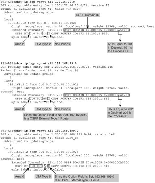
- OSPF Route Type – Propagates OSPF route type information across the MP-iBGP backbone. Figure 5-4 shows the OSPF route type extended communities attribute. Figure 5-5 depicts the OSPF route type detail for prefix 172.16.20.0, 192.168.99.0, and 192.168.199.0.
- OSPF router ID – Identifies the router ID of the PE in the relevant VRF instance of OSPF. This address is not part of the provider's address space and is unique in the OSPF network.
- OSPF domain ID – Identifies the domain of a specific OSPF prefix in the MPLS VPN backbone. By default, this value is equal to the value of the OSPF process ID and can be overwritten by the command domain ID ip-address under the OSPF process. If the domain ID of the route does not match the domain ID on the receiving PE, the route is translated to the external OSPF route (LSA Type 5) with metric-type E2, assuming the route was received in the VRF table. All routing between OSPF domains is via Type 5 LSAs.
Figure 5-4. OSPF Route Type, Router ID, and Domain ID
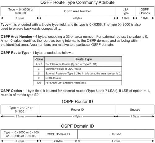
Figure 5-5. OSPF Route Type, Router ID, and Domain ID Detail for 172.16.20.0, 192.168.99.0, and 192.168.199.0
OSPF Route-Propagation Using MPLS VPN Superbackbone Concept
OSPF route propagation in an MPLS VPN environment is not as traditional as the OSPF routing model and depends on the OSPF domain ID. By default, the OSPF domain ID is equal to the process ID configured on the PE router. The domain ID is set in the VPNv4 update when the OSPF route is redistributed into MP-iBGP.
OSPF Domain ID Is Same on All PE Routers
Figure 5-6 shows an MPLS network providing MPLS VPN services to Customer A. CE routers CE1-A and CE2-A at site networks 172.16.10.0/24 and 172.16.20.0/24 are in Area 1 and Area 2, respectively, while PE-CE links at both sites are in Area 0. OSPF process ID on both PE routers is 101. In addition, CE2-A functions as a traditional ASBR between the OSPF domain and external routing domains RIPv2 and EIGRP (AS101).
Figure 5-6. Route Propagation When OSPF Domain (Process) ID Is Same
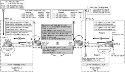
The following sequence takes place when CE2-A is sending 172.16.20.0/24, 209.165.127.0/27, and 209.165.202.128/27 to CE1-A:
- CE2-A redistributes RIPv2 network 209.165.201.1 into OSPF and propagates it as an OSPF external Type 1 route (O E1) to PE2-AS1. EIGRP network 209.165.202.128/27 is redistributed at CE2-A and propagated as an OSPF external Type 2 (O E2) to PE2-AS1. CE2-A also sends 172.16.20.0/24 as an inter-area route (O IA) to PE2-AS1.
- VRF Cust_A routing table on PE2-AS1 shows the received routes 172.16.20.0/24 as OSPF inter-area route with OSPF metric (cost) 74, 209.165.127.0/27 as an external Type 1 route with OSPF metric 84, and 209.165.202.128/27 route with OSPF metric 20.
- As shown in Figure 5-6, the OSPF cost for 172.16.20.0/24, 209.165.127.0/27, and 209.165.202.128/27 is copied into extended BGP attributes as BGP MEDs when OSPF is redistributed into MP-BGP. The routes 172.16.20.0, 209.165.127.0, and 209.165.202.128/27 are then propagated to PE1-AS1 via MP-iBGP session.
- PE1-AS1 receives the BGP VPNv4 routes 172.16.20.0/24, 209.165.127.0/27, and 209.165.202.128/27 from PE2-AS1 and inserts them in the BGP table. As illustrated in Figure 5-6, the OSPF metric for the routes are not altered and remain the same when propagated though the MP-BGP backbone.
- The receiving PE router, PE1-AS1, redistributes the MP-BGP routes back into OSPF, verifies the domain ID, and if the domain ID of the route matches the domain ID on the receiving PE, PE1-AS1, it uses the original LSA type and the MED attribute to generate an inter-area summary (LSA Type 3) LSA. In Figure 5-6, the domain ID matches the domain ID on PE1-AS1, so PE1-AS1 reconstructs the original update and updates the metric based on the outgoing interfaces and propagates the 172.16.20.0/24 as an inter-area route to CE1-A. 209.165.127.0/24 and 209.165.202.128/27 are propagated as OSPF external Type 1 and Type 2 to CE1-A.
- CE1-A receives the 172.16.20.0 as an inter-area route and 209.165.127.0 and 209.165.202.128/27 as OSPF external routes.
OSPF Domain ID Is Different on All PE Routers
As previously mentioned, OSPF domain ID by default is equal to the OSPF process ID configured on PE routers unless modified manually. If the process IDs are different on PE routers for sites belonging to same VPN, OSPF routes are seen as OSPF external routes (Type 5 OSPF LSA). As shown in Figure 5-7, when the PE1-AS1 router in OSPF Area 1 uses OSPF process ID 201 for Site 1 belonging to VPN VPN-A, and the PE2 router in OSPF Area 2 uses OSPF process ID 202 for Site 2 belonging to VPN VPN-A, external routes are seen at Site 1 for Site 2 networks and vice versa.
Figure 5-7. Route Propagation When OSPF Domain (Process) ID Is Different
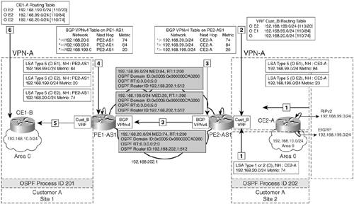
The following sequence of events takes place when CE2-A is sending 192.168.20.0, 192.168.99.0, and 192.168.199.0 to CE1-A:
- CE2-B redistributes RIPv2 network 192.168.99.0 into OSPF and propagates it as an OSPF external Type 1 route (O E1) to PE2-AS1. EIGRP network 192.168.199.0/24 is redistributed and propagated as an OSPF external Type 2 (O E2) to PE2-AS1. CE2-B also sends 192.168.20.0/24 as an intra-area route (O) to PE2-AS1.
- VRF Cust_B routing table on PE2-AS1 shows the received routes: 192.168.20.0 as an OSPF inter-area route with OSPF metric 74, 192.168.99.0/24 as an external Type 1 route with OSPF metric 84, and 192.168.199.0/24 is preserved as an external Type 2 route with OSPF metric 20.
- The PE router, PE2-AS1, redistributes the OSPF routes 192.168.20.0, 192.168.99.0, and 192.168.199.0/27 into MP-BGP, copies the OSPF cost for those routes into the multi-exit discriminator (MED) attribute, and sets the BGP extended community route type (RT) to indicate the LSA type from which the route was derived, as well as the extended community attribute OSPF domain ID to indicate the process number of the source OSPF process. OSPF RTs carry information on the original area. The LSA type and the type for external routes are metric types.
- PE1-AS1 receives the BGP VPNv4 routes 192.168.20.0, 192.168.99.0, and 192.168.199.0/27 with the same metric information from PE2-AS1. The information received is inserted in the BGP table. As shown in the figure, the OSPF metric for the routes are not altered and remain the same when propagated though the MP-BGP backbone.
- PE2-AS1 checks the attributes received in the route, and, because the domain ID of the route does not match the domain ID on the receiving PE, the route is translated to the external Type 2 route (LSA Type 5) OSPF route. In this case, the domain ID matches the domain ID on PE1-AS1; therefore, PE1-AS1 will reconstruct the original update and update the metric based on the outgoing interfaces and propagate 192.168.20.0 as an inter-area route to CE1-B. 192.168.99.0 and 192.168.199.0/27 are propagated as OSPF external Type 1 and Type 2 to CE1-B.
- CE1-B receives the 192.168.20.0 as an inter-area route and 192.168.99.0 and 192.168.199.0/24 as OSPF external routes.
Impact of Configuring OSPF Domain ID on PE Routers
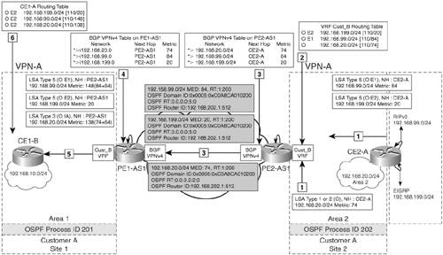
Manually configuring the OSPF domain ID changes the behavior of routes for Layer 3 VPNs connecting multiple OSPF domains. Configuring domain IDs helps control LSA translation (for Type 3 and Type 5 LSAs) between the OSPF domains and backdoor paths. The default domain ID is 0.0.0.0. Each VPN routing table on a PE router associated with an OSPF routing instance is configured with the same OSPF domain ID. Domain IDs are, hence, used to identify whether the routes originated from the OSPF domain or from external routing protocols. The OSPF domain ID helps identify which OSPF domain a route originated from, which allows classification of routes as Type 3 LSAs or Type 5 LSAs. In Figure 5-7, it is difficult to identify which routes received on CE1-A originated within OSPF or from external routing domains. As shown in Figure 5-8, by manually configuring the domain ID to be the same on PE1-AS1 and PE2-AS1, we can correctly identify which routes are external and which are internal.
Figure 5-8. Route Propagation When OSPF Domain (Process) ID Is Manually Configured to Be the Same
OSPF Down Bit and Domain Tag
Routing loops can occur in the MPLS VPN environment when customer edge routers are dual-homed to the service provider network. Figure 5-9 shows an MPLS VPN network implementing OSPF PE-CE routing for Customer A VPN-A sites, Site 1 and Site 2. Site 2 is in OSPF Area 2 and has multiple connections to the provider backbone.
Figure 5-9. Route Propagation (OSPF Down Bit Not Set)

As shown in Figure 5-9, the following sequence takes place, which can lead to a potential routing loop:
- CE1-A sends a Type 1 router or Type 2 network LSA to the provider edge router, PE1.
- PE1 router receives the intra-area OSPF route from CE1-A and redistributes it into MP-BGP.
- The receiving PE router, PE2, redistributes the MP-BGP route into OSPF Area 2 as an inter-area summary route, LSA Type 3.
- The summary route is propagated across the OSPF area and received by the other PE router, PE3, attached to the same area, Area 2.
- PE3 selects the OSPF route, because the administrative distance of the OSPF route is better than the administrative distance of the MP-iBGP route. PE3, therefore, redistributes the route OSPF back into the MP-BGP process, potentially resulting in a routing loop.
OSPF Down Bit
The routing loop shown in Figure 5-9 can be prevented by the use of the OSPF down bit, which is part of the options field in the OSPF header. The LSA header with the option field is shown in Figure 5-10.
Figure 5-10. LSA Header and OSPF Down Bit
Figure 5-11 shows how the OSPF down bit is used to prevent the routing loop shown in Figure 5-10.
Figure 5-11. Route Propagation When OSPF Down Bit Is Set
The following is the route propagation when the OSPF down bit is set:
- CE1-A sends a Type 1 router or Type 2 network LSA to the provider edge router, PE1.
- The PE1 router receives the intra-area OSPF route from CE1-A and redistributes it into MP-BGP.
- The receiving PE router, PE2, redistributes the MP-BGP route into OSPF Area 2 as an inter-area summary route, LSA Type 3, with the OSPF down bit set.
- The summary route with the down bit set is propagated across the OSPF area and received by PE3, which is attached to the same area, Area 2.
- When the PE3 router receives the summary LSA with the down bit set, it does not redistribute the route back into MP-BGP.
OSPF Route Tag or VPN Route Tag
The down bit helps prevent routing loops between MP-BGP and OSPF, but not when external routes are announced, such as when redistribution between multiple OSPF domains or when external routes are injected in an area that is dual-homed to the provider network. The PE router redistributes an OSPF route from a different OSPF domain into an OSPF domain as an external route. The down bit is not set because LSA Type 5 does not support the down bit. The redistributed route is propagated across the OSPF domain.
A non-MPLS router can then redistribute the OSPF route into another OSPF domain. The OSPF route is propagated through the other OSPF domain, again without the down bit. A PE router receives the OSPF route. When the down bit is missing, the route is redistributed back into the MP-BGP backbone, resulting in a routing loop. This is shown in Figure 5-12 when external routes are propagated into the VPN sites.
Figure 5-12. External Route Propagation in Dual-Homed CE

The following sequence of steps takes place:
|
1. |
CE2-A sends a Type 5 LSA for 209.165.201.0/27 to the provider edge router, PE2-AS1. |
|
2. |
The PE2-AS1 router receives the external (O E1) OSPF route from CE2-A with the OSPF down bit set and then redistributes it into MP-BGP. |
|
3. |
Assuming the receiving PE router is PE1-AS1, and, because it is redistributing to a different OSPF domain (201), PE1-AS1 clears the OSPF down bit and propagates the route to CE1-A as an external (O E1) route, LSA Type 5. |
|
4. |
CE1-A receives the route without the OSPF down bit set and propagates the external route to PE3-AS1. |
|
5. |
When the PE3-AS1 router receives the external route without the down bit set, it redistributes the route back into MP-BGP. |
|
6. |
PE3-AS1, therefore, propagates the route to PE1-AS1 and PE2-AS1, which might cause a routing loop. |
The routing loops introduced by route redistribution between OSPF domains can be solved with the help of the tag field, using standard BGP-OSPF redistribution rules. A non-OSPF route is redistributed as an external OSPF route by a PE router. By default, the tag field is set to the BGP-AS number. The redistributed route is propagated across the OSPF domain without the down bit but with the tag field set. When the route is redistributed into another OSPF domain, the tag field is propagated. Another PE router receives the external OSPF route and filters the route based on the tag field. The tag field matches the AS number so the route is not redistributed into MP-BGP.
Configuring and Verifying OSPF PE-CE Routing
The configuration flowchart for implementing OSPF PE-CE routing is shown in Figure 5-13.
Figure 5-13. Configuration Flowchart for OSPF PE-CE Routing

Note
Cisco IOS versions prior to 12.3(4)T, 12.0(27)S, and 12.2(25)S have the limitation of 32 processes in which a separate OSPF process has to be created for each VRF so that the PE router can identify the OSPF routes belonging to the correct process. In an MPLS VPN environment, one process is used by MP-iBGP, one by an IGP routing protocol (OSPF, for example), one process for connected routes, and another for static routes. Therefore, out of 32, only 28 processes could be created for VRFs using OSPF PE-CE routing until the above mentioned versions.
Configuration Scenario 1 – OSPF Process ID Is Same for Customer A and Different for Customer B VPNs
The objective of this setup is to understand how the OSPF process ID plays a part in deciding the type of route seen on customer edge routers running OSPF. Figure 5-14 shows MPLS VPN services being provided to Customer A and Customer B sites:
- Customer A network – Customer A has CE1-A and CE2-A located in the same VPN, VPN-A. They are part of the same OSPF domain. PE1-AS1 and PE2-AS1 have OSPF process ID 101 configured for VRF Cust_A on PE1-AS1 and PE2-AS1.
- Customer B network – Customer B has CE1-B and CE2-B located in the VPN, VPN-B. PE1-AS1 and PE2-AS1 have OSPF process IDs of 201 and 202 for Cust_B VRFs, respectively.
Figure 5-14. MPLS VPN Network Implementing OSPF PE-CE Routing

Before configuring, ensure that the provider network is provisioned to deliver MPLS VPN services to Customer A and B sites. Ensure that IP addresses are preconfigured and VRFs defined on PE routers. Example 5-1 provides the configuration for defining VRF and its attributes on PE routers for OSPF PE-CE routing for VRF Cust_A (Customer A).
Example 5-1. Define VRF Cust_A on PE Routers PE1-AS1 and PE2-AS1
PE1-AS1(config)#ip vrf Cust_A

PE1-AS1(config-vrf)# rd 1:100

PE1-AS1(config-vrf)# route-target both 1:100

PE1-AS1(config)#interface Serial1/0

PE1-AS1(config-if)# description connected to CE1-A

PE1-AS1(config-if)# ip vrf forwarding Cust_A

PE1-AS1(config-if)# ip address 172.16.1.1 255.255.255.252

_________________________________________________________________________

PE2-AS1(config)#ip vrf Cust_A

PE2-AS1(config-vrf)# rd 1:100

PE2-AS1(config-vrf)# route-target both 1:100

PE2-AS1(config)#interface Serial1/0

PE2-AS1(config-if)# description connected to CE2-A

PE2-AS1(config-if)# ip vrf forwarding Cust_A

PE2-AS1(config-if)# ip address 172.16.2.1 255.255.255.252
The steps to configure OSPF PE-CE routing on the PE routers are
|
Step 1. |
Enable per VRF OSPF Routing – Enable per VRF OSPF routing for VRF Cust_A on PE routers PE1-AS1 and PE2-AS1 for Customer A and Cust_B on PE1-AS1 and PE2-AS1 for Customer B. Example 5-2 illustrates the configuration for enabling OSPF routing for the VRF Cust_A. Example 5-2. Enable per VRF OSPF Routing for Cust_A on PE1-AS1 and PE2-AS1 PE1-AS1(config)#router ospf 101 vrf Cust_A PE1-AS1(config-router)# router-id 172.16.101.1 PE1-AS1(config-router)# network 172.16.0.0 0.0.255.255 area 0 __________________________________________________________________ PE2-AS1(config)#router ospf 101 vrf Cust_A PE2-AS1(config-router)# router-id 172.16.102.1 PE2-AS1(conig-router)# network 172.16.0.0 0.0.255.255 area 0 |
|
Step 2. |
Redistribute OSPF Routes in BGP – In this step, the OSPF routes received from the local CE routers is redistributed in MP-iBGP. It is necessary to include the match command option; otherwise, only OSPF internal routes will be redistributed in BGP. Example 5-3 shows the procedure to configure redistribution of OSPF routes in BGP. Example 5-3. Redistribute OSPF Routes in MP-BGP PE1-AS1(config)#router bgp 1 PE1-AS1(config-router)#address-family ipv4 vrf Cust_A PE1-AS1(config-router-af)#redistribute ospf 101 vrf Cust_A match internal external 1 external 2 __________________________________________________________________________________ PE2-AS1(config)#router bgp 1 PE2-AS1(config-router)#address-family ipv4 vrf Cust_A PE2-AS1(config-router-af)#redistribute ospf 101 vrf Cust_A match internal external 1 external 2 |
|
Step 3. |
Redistribute MP-IBGP in OSPF – In this step, you redistribute the BGP VPNv4 routes into OSPF on PE routers, PE1-AS1 and PE2-AS1. Ensure that the subnets keyword is included when configuring redistribution; otherwise, Cisco IOS redistributes only the major networks and supernets. Example 5-4 shows the steps on PE1-AS1. Repeat the same steps on PE2-AS1. Example 5-4. Redistribute MP-IBGP in OSPF PE1-AS1(config)#router ospf 100 vrf Cust_A PE1-AS1(config-router)# redistribute bgp 1 subnets ________________________________________________________________ PE2-AS1(config)#router ospf 100 vrf Cust_A PE2-AS1(config-router)# redistribute bgp 1 subnets |
Final Configuration for Provider and Edge Routers
Example 5-5 shows the configuration for PE1-AS1, PE2-AS1, and P1-AS1.
Example 5-5. PE1-AS1, PE2-AS1, and P1-AS1 Configuration
hostname PE1-AS1

!

ip cef

!

ip vrf Cust_A

 rd 1:100

 route-target export 1:100

 route-target import 1:100

!

ip vrf Cust_B

 rd 1:200

 route-target export 1:200

 route-target import 1:200

!

interface Loopback0

 ip address 10.10.10.101 255.255.255.255

!

interface Loopback101

 description OSPF Router ID for VRF Cust_A

 ip vrf forwarding Cust_A

 ip address 172.16.101.1 255.255.255.255

!

interface Loopback201

 description OSPF Router ID for VRF Cust_B

 ip vrf forwarding Cust_B

 ip address 192.168.201.1 255.255.255.255

!

interface Serial0/0

 description connected to P1-AS1

 ip address 10.10.10.1 255.255.255.252

 mpls ip

!

interface Serial1/0

 description connected to CE1-A

 ip vrf forwarding Cust_A

 ip address 172.16.1.1 255.255.255.252

!

interface Serial2/0

 description connected to CE1-B

 ip vrf forwarding Cust_B

 ip address 192.168.1.1 255.255.255.252

!

router ospf 101 vrf Cust_A

 router-id 172.16.101.1

 redistribute bgp 1 subnets

 network 172.16.0.0 0.0.255.255 area 0

!

router ospf 201 vrf Cust_B

 router-id 192.168.201.1

 redistribute bgp 1 subnets

 network 192.168.0.0 0.0.255.255 area 1

!

router ospf 1

 router-id 10.10.10.101

 network 10.0.0.0 0.255.255.255 area 0

!

router bgp 1

 no synchronization

 neighbor 10.10.10.102 remote-as 1

 neighbor 10.10.10.102 update-source Loopback0

 no auto-summary

 !

 address-family vpnv4

 neighbor 10.10.10.102 activate

 neighbor 10.10.10.102 send-community extended

 exit-address-family

 !

 address-family ipv4 vrf Cust_B

 redistribute ospf 201 vrf Cust_B match internal external 1 external 2

 no auto-summary

 no synchronization

 exit-address-family

 !

 address-family ipv4 vrf Cust_A

 redistribute ospf 101 vrf Cust_A match internal external 1 external 2

 no auto-summary

 no synchronization

 exit-address-family

__________________________________________________________________________

hostname PE2-AS1

!

ip cef

!

ip vrf Cust_A

 rd 1:100

 route-target export 1:100

 route-target import 1:100

!

ip vrf Cust_B

 rd 1:200

 route-target export 1:200

 route-target import 1:200

!

interface Loopback0

 ip address 10.10.10.102 255.255.255.255

!

interface Loopback101

 description OSPF Router ID for VRF Cust_A

 ip vrf forwarding Cust_A

 ip address 172.16.102.1 255.255.255.255

!

interface Loopback202

 description OSPF Router ID for VRF Cust_B

 ip vrf forwarding Cust_B

 ip address 192.168.202.1 255.255.255.255

!

interface Serial0/0

 description connected to P1-AS1

 ip address 10.10.10.5 255.255.255.252

 mpls ip

!

interface Serial1/0

 description connected to CE2-A

 ip vrf forwarding Cust_A

 ip address 172.16.2.1 255.255.255.252

!

interface Serial2/0

 description connected to CE2-B

 ip vrf forwarding Cust_B

 ip address 192.168.2.1 255.255.255.252

!

router ospf 101 vrf Cust_A

 router-id 172.16.102.1

 redistribute bgp 1 subnets

 network 172.16.0.0 0.0.255.255 area 0

!

router ospf 202 vrf Cust_B

 router-id 192.168.202.1

 redistribute bgp 1 subnets

 network 192.168.0.0 0.0.255.255 area 2

!

router ospf 1

 router-id 10.10.10.102

 network 10.0.0.0 0.255.255.255 area 0!

router bgp 1

 no synchronization

 neighbor 10.10.10.101 remote-as 1

 neighbor 10.10.10.101 update-source Loopback0

 no auto-summary

 !

 address-family vpnv4

 neighbor 10.10.10.101 activate

 neighbor 10.10.10.101 send-community extended

 exit-address-family

 !

 address-family ipv4 vrf Cust_B

 redistribute ospf 202 vrf Cust_B match internal external 1 external 2

 no auto-summary

 no synchronization

 exit-address-family

 !

 address-family ipv4 vrf Cust_A

 redistribute ospf 101 vrf Cust_A match internal external 1 external 2

 no auto-summary

 no synchronization

 exit-address-family

___________________________________________________________________________

hostname P1-AS1

!

interface Loopback0

 ip address 10.10.10.200 255.255.255.255

!

interface Serial0/0

 description connected to PE1-AS1

 ip address 10.10.10.2 255.255.255.252

 mpls ip

!

interface Serial1/0

 description connected to PE2-AS1

 ip address 10.10.10.6 255.255.255.252

 mpls ip

!

router ospf 1

 log-adjacency-changes

 network 10.0.0.0 0.255.255.255 area 0
Example 5-6 shows the configuration for CE1-A, CE2-A, CE1-B, and CE2-B.
Example 5-6. CE1-A, CE2-A, CE1-B, and CE2-B Configuration
hostname CE1-A

!

interface Ethernet0/0

 description VPN-A Site 1 network

 ip address 172.16.10.1 255.255.255.0

!

interface Serial1/0

 description connected to PE1-AS1

 ip address 172.16.1.2 255.255.255.252

!

router ospf 101

 network 172.16.1.0 0.0.0.255 area 0

 network 172.16.10.0 0.0.0.255 area 1

__________________________________________________________________________

hostname CE2-A

!

interface Loopback0

description RIPv2 network

 ip address 209.165.201.1 255.255.255.224

!

interface Loopback1

description EIGRP network

 ip address 209.165.202.129 255.255.255.224

!

interface Ethernet0/0

 description VPN-A Site 2 network

 ip address 172.16.20.1 255.255.255.0

!

interface Serial1/0

 description connected to PE2-AS1

 ip address 172.16.2.2 255.255.255.252

!

router eigrp 1

 network 209.165.202.0

 no auto-summary

!

router ospf 101

 redistribute eigrp 1 subnets

 redistribute rip metric-type 1 subnets

 network 172.16.2.0 0.0.0.255 area 0

 network 172.16.20.0 0.0.0.255 area 2

 !

router rip

 version 2

 redistribute ospf 101 match internal external 1 external 2

 network 209.165.201.0

 no auto-summary

__________________________________________________________________________

hostname CE1-B

!

interface Ethernet0/0

 description VPN-B Site1 network

 ip address 192.168.10.1 255.255.255.0

!

interface Serial1/0

 description connected to PE1-AS1

 ip address 192.168.1.2 255.255.255.252

!

router ospf 201

 network 192.168.1.0 0.0.0.255 area 1

 network 192.168.10.0 0.0.0.255 area 1

__________________________________________________________________________

hostname CE2-B

!

interface Loopback0

 ip address 192.168.99.1 255.255.255.0

!

interface Loopback1

 ip address 192.168.199.1 255.255.255.0

!

interface Ethernet0/0

 description VPN-B Site 2 network

 ip address 192.168.20.1 255.255.255.0

 !

interface Serial1/0

 description connected to PE2-AS1

 ip address 192.168.2.2 255.255.255.252

 !

router eigrp 1

 redistribute ospf 202 metric 1500 1 255 1 1500 match internal external 1 external 2

 network 192.168.199.0

 no auto-summary

!

router ospf 202

 redistribute eigrp 1 subnets

 redistribute rip metric-type 1 subnets

 network 192.168.2.0 0.0.0.255 area 2

 network 192.168.20.0 0.0.0.255 area 2

!

router rip

 version 2

 redistribute ospf 202 metric 1 match internal external 1 external 2

 network 192.168.99.0

 no auto-summary
Verify OSPF PE-CE Routing
The steps to verify OSPF PE-CE routing are as follows:
|
Step 1. |
Verify OSPF neighbor adjacency – This step ensures that there is an OSPF neighbor relationship and adjacency is formed between the provider edge (PE) router and customer edge (CE) router. Example 5-7 shows the output on the PE and CE router where the adjacency is formed, indicated by the FULL state. Example 5-7. show ip ospf neighbor on PE1-AS1 and PE2-AS1 PE1-AS1#show ip ospf neighbor Neighbor ID Pri State Dead Time Address Interface 10.10.10.200 0 FULL/ - 00:00:38 10.10.10.2 Serial0/0 192.168.10.1 0 FULL/ - 00:00:35 192.168.1.2 Serial2/0 172.16.10.1 0 FULL/ - 00:00:32 172.16.1.2 Serial1/0 ____________________________________________________________________________ PE2-AS1#show ip ospf neighbor Neighbor ID Pri State Dead Time Address Interface 10.10.10.200 0 FULL/ - 00:00:39 10.10.10.6 Serial0/0 192.168.20.1 0 FULL/ - 00:00:38 192.168.2.2 Serial2/0 172.16.20.1 0 FULL/ - 00:00:32 172.16.2.2 Serial1/0 |
|
Step 2. |
Verify route propagation for Customer A – These steps verify route propagation for 192.168.20.0, 192.168.99.0, and 192.168.199.0. Example 5-8. show ip route vrf Cust_A ospf 101 on PE2-AS1 PE2-AS1#show ip route vrf Cust_A ospf 101 172.16.0.0/16 is variably subnetted, 6 subnets, 3 masks O IA 172.16.20.0/24 [110/74] via 172.16.2.2, 01:14:00, Serial1/0 209.165.201.0/27 is subnetted, 1 subnets O E1 209.165.201.0 [110/84] via 172.16.2.2, 01:14:00, Serial1/0 209.165.202.0/27 is subnetted, 1 subnets O E2 209.165.202.128 [110/20] via 172.16.2.2, 01:14:00, Serial1/0 Cust_A OSPF routes are redistributed in MP-iBGP, and the OSPF metrics for 172.16.20.0, 209.165.127.0, and 209.165.202.128/27 are copied into extended BGP attributes as BGP MEDs. The routes 172.16.20.0/24, 209.165.201.0/27, and 209.165.202.128/27 are then propagated to PE1-AS1 via MP-iBGP session. Example 5-9 displays output of the show ip bgp vpn vrf Cust_A command on PE2-AS1. Example 5-10 displays output of the show ip bgp vpnv4 all 172.16.20.0 command on PE2-AS1. Example 5-9. show ip bgp vpn vrf Cust_A on PE2-AS1 PE2-AS1#show ip bgp vpn vrf Cust_A Network Next Hop Metric LocPrf Weight Path Route Distinguisher: 1:100 (default for vrf Cust_A) *> 172.16.20.0 172.16.2.2 74 32768 ? *> 209.165.201.0 172.16.2.2 84 32768 ? *> 209.165.202.128 172.16.2.2 20 32768 ? Example 5-10. show ip bgp vpnv4 all 172.16.20.0 on PE2-AS1 PE2-AS1#show ip bgp vpnv4 all 172.16.20.0 BGP routing table entry for 1:100:172.16.20.0/24, version 138 Paths: (1 available, best #1, table Cust_A) Advertised to update-groups: 1 Local 172.16.2.2 from 0.0.0.0 (10.10.10.102) Origin incomplete, metric 74, localpref 100, weight 32768, valid, sourced, best Extended Community: RT:1:100 OSPF DOMAIN ID:0x0005:0x000000650200 OSPF RT:0.0.0.0:3:0 OSPF ROUTER ID:172.16.102.1:512, mpls labels in/out 34/nolabel At PE1-AS1, the routes are received with metrics unchanged from their origination at PE2-AS1. PE1-AS1 redistributes the MP-BGP route back into OSPF, verifies the domain ID, and, if the domain ID of the route matches the domain ID on PE1-AS1, it uses the original LSA type and the MED attribute to generate an inter-area summary (LSA Type 3) LSA; otherwise, it generates an external route. In this case, the OSPF domain ID matches, and 172.16.20.0 is generated as an inter-area route to CE1-A, and the metric is modified to 138 (74 [original metric] + 64 [outgoing interface cost on PE1-AS1 to CE1-A, in this case, serial link = 64]). Example 5-11 displays output from the show ip bgp vpnv4 vrf Cust_A on PE1-AS1. Example 5-12 displays output from the show ip route ospf command on CE1-A. Example 5-11. show ip bgp vpnv4 vrf Cust_A on PE1-AS1 PE1-AS1#show ip bgp vpnv4 vrf Cust_A Network Next Hop Metric LocPrf Weight Path Route Distinguisher: 1:100 (default for vrf Cust_A) *> 172.16.1.0/30 0.0.0.0 0 32768 ? *>i172.16.2.0/30 10.10.10.102 0 100 0 ? *> 172.16.10.0/24 172.16.1.2 74 32768 ? *>i172.16.20.0/24 10.10.10.102 74 100 0 ? *> 172.16.101.1/32 0.0.0.0 0 32768 ? *>i172.16.102.1/32 10.10.10.102 0 100 0 ? *>i209.165.201.0/27 10.10.10.102 84 100 0 ? *>i209.165.202.128/27 10.10.10.102 20 100 0 ? Example 5-12. show ip route ospf on CE1-A CE1-A#show ip route ospf 172.16.0.0/16 is variably subnetted, 6 subnets, 3 masks O IA 172.16.20.0/24 [110/138] via 172.16.1.1, 01:15:26, Serial1/0 O IA 172.16.2.0/30 [110/65] via 172.16.1.1, 01:15:26, Serial1/0 O 172.16.101.1/32 [110/65] via 172.16.1.1, 01:16:13, Serial1/0 O IA 172.16.102.1/32 [110/65] via 172.16.1.1, 01:15:26, Serial1/0 209.165.201.0/27 is subnetted, 1 subnets O E1 209.165.201.0 [110/148] via 172.16.1.1, 01:15:21, Serial1/0 209.165.202.0/27 is subnetted, 1 subnets O E2 209.165.202.128 [110/20] via 172.16.1.1, 01:15:21, Serial1/0 |
|
Step 3. |
Verify route propagation for Customer B – These steps verify route propagation for 192.168.20.0, 192.168.99.0, and 192.168.199.0. Example 5-13. show ip route vrf Cust_B ospf 202 on PE2-AS1 PE2-AS1#show ip route vrf Cust_B ospf 202 O E2 192.168.199.0/24 [110/20] via 192.168.2.2, 00:39:02, Serial2/0 O E1 192.168.99.0/24 [110/84] via 192.168.2.2, 00:39:02, Serial2/0 O 192.168.20.0/24 [110/74] via 192.168.2.2, 00:39:02, Serial2/0 Cust_B OSPF routes are redistributed in MP-iBGP, and the OSPF metrics for 192.168.20.0, 192.168.99.0, and 192.168.199.0 are copied into extended BGP attributes as BGP MEDs. The routes are then propagated to PE1-AS1 via MP-iBGP session. Example 5-14 displays output from the show ip bgp vpnv4 all | begin 192.168.20.0 command on PE2-AS1. Example 5-15 displays output from the show ip bgp vpnv4 all 192.168.99.0 command on PE2-AS1. Example 5-14. show ip bgp vpnv4 all | begin 192.168.20.0 on PE2-AS1 PE2-AS1#show ip bgp vpnv4 all | begin 192.168.20.0 *> 192.168.20.0 192.168.2.2 74 32768 ? *> 192.168.99.0 192.168.2.2 84 32768 ? *> 192.168.199.0 192.168.2.2 20 32768 ? Example 5-15. show ip bgp vpnv4 all 192.168.99.0 on PE2-AS1 PE2-AS1#show ip bgp vpnv4 all 192.168.99.0 BGP routing table entry for 1:200:192.168.99.0/24, version 145 Paths: (1 available, best #1, table Cust_B) Advertised to update-groups: 1 Local 192.168.2.2 from 0.0.0.0 (10.10.10.102) Origin incomplete, metric 84, localpref 100, weight 32768, valid, sourced, best Extended Community: RT:1:200 OSPF DOMAIN ID:0x0005:0x000000CA0200 OSPF RT:0.0.0.0:5:0 OSPF ROUTER ID:192.168.202.1:512, mpls labels in/out 28/nolabel At PE1-AS1, the routes are received with metrics unchanged. PE1-AS1 redistributes the MP-BGP routes back into OSPF, verifies the domain ID, and, if the domain ID of the route matches the domain ID on PE1-AS1, it uses the original LSA type and the MED attribute to generate an inter-area summary (LSA Type 3) LSA; otherwise, it generates an external route. In this case, the OSPF domain ID does not match, so 192.168.20.0 is generated as an external route. Example 5-16 displays output from the show ip bgp vpnv4 all | begin 192.168.20.0 command on PE1-AS1. Example 5-17 displays output from the show ip route ospf command on CE1-B. Example 5-16. show ip bgp vpnv4 all 192.168.99.0 on PE1-AS1 PE1-AS1#show ip bgp vpnv4 all | begin 192.168.20.0 *>i192.168.20.0 10.10.10.102 74 100 0 ? *>i192.168.99.0 10.10.10.102 84 100 0 ? *>i192.168.199.0 10.10.10.102 20 100 0 ? Example 5-17. show ip route ospf on CE1-B CE1-B#show ip route ospf O E2 192.168.199.0/24 [110/20] via 192.168.1.1, 00:48:46, Serial1/0 192.168.201.0/32 is subnetted, 1 subnets O 192.168.201.1 [110/65] via 192.168.1.1, 00:49:33, Serial1/0 O E2 192.168.99.0/24 [110/84] via 192.168.1.1, 00:48:46, Serial1/0 O E2 192.168.20.0/24 [110/74] via 192.168.1.1, 00:48:46, Serial1/0 192.168.202.0/32 is subnetted, 1 subnets O E2 192.168.202.1 [110/1] via 192.168.1.1, 00:48:46, Serial1/0 192.168.2.0/30 is subnetted, 1 subnets O E2 192.168.2.0 [110/1] via 192.168.1.1, 00:48:46, Serial1/0 |
Configuration Scenario 2 – Using OSPF Domain ID Support for LSA Type 5/Type 3 Translation
Figure 5-15 shows an MPLS VPN network for Customer B in which CE1-B and CE2-B belong to the same VPN but have different process IDs. Configuring domain IDs helps control LSA translation (for Type 3 and Type 5 LSAs) between the OSPF domains and backdoor paths. Each VPN routing table in a PE router associated with an OSPF routing instance is configured with the same OSPF domain ID.
Figure 5-15. MPLS VPN Network Using Domain ID Support
Configuration for this section remains the same as shown in configuration Scenario 1. Configuring domain ID ip-address under the OSPF routing process for VRF Cust_B is the only addition in this section. The configuration step is outlined here:
- Configure OSPF domain ID – Configure domain ID ip-address under the OSPF routing process for Cust_B. The domain ID has to be common for all PE routers for that VPN instance. Use loopback 202 on PE2 as the domain ID for Customer B. Example 5-18 shows how to configure the OSPF domain ID.
Example 5-18. Configuring OSPF Domain ID
PE1-AS1(config)#router ospf 201 vrf Cust_B

PE1-AS1(config-router)# domain ID 192.168.202.1

__________________________________________________________________________

PE2-AS1(config)#router ospf 202 vrf Cust_B

PE2-AS1(config-router)# domain ID 192.168.202.1
Verify Route Propagation When Using OSPF Domain ID
Example 5-19 shows that when the OSPF domain ID is not configured, the CE1-B routing table shows all the routes being external.
Example 5-19. Routing Table on CE1-B When OSPF Domain ID Is Not Configured
CE1-B#show ip route ospf

O E2 192.168.199.0/24 [110/20] via 192.168.1.1, 00:00:08, Serial1/0

 192.168.201.0/32 is subnetted, 1 subnets

O 192.168.201.1 [110/65] via 192.168.1.1, 00:00:14, Serial1/0

O E2 192.168.99.0/24 [110/84] via 192.168.1.1, 00:00:08, Serial1/0

O E2 192.168.20.0/24 [110/74] via 192.168.1.1, 00:00:08, Serial1/0

 192.168.202.0/32 is subnetted, 1 subnets

O E2 192.168.202.1 [110/1] via 192.168.1.1, 00:00:14, Serial1/0

 192.168.2.0/30 is subnetted, 1 subnets

O E2 192.168.2.0 [110/1] via 192.168.1.1, 00:00:14, Serial1/0
Example 5-20 shows that when the OSPF domain ID is configured, the CE1-B routing table shows 192.168.20.0 as inter-area and 192.168.99.0 as external Type 1.
Example 5-20. Routing Table on CE1-B When OSPF Domain ID Is Configured
CE1-B#show ip route ospf

O E2 192.168.199.0/24 [110/20] via 192.168.1.1, 00:44:09, Serial1/0

 192.168.201.0/32 is subnetted, 1 subnets

O 192.168.201.1 [110/65] via 192.168.1.1, 00:45:15, Serial1/0

O E1 192.168.99.0/24 [110/148] via 192.168.1.1, 00:44:09, Serial1/0

O IA 192.168.20.0/24 [110/138] via 192.168.1.1, 00:44:14, Serial1/0

 192.168.202.0/32 is subnetted, 1 subnets

O E2 192.168.202.1 [110/1] via 192.168.1.1, 00:44:09, Serial1/0

 192.168.2.0/30 is subnetted, 1 subnets

O E2 192.168.2.0 [110/1] via 192.168.1.1, 00:44:09, Serial1/0
OSPF Sham-Links
Figure 5-16 shows an MPLS-enabled service provider network providing MPLS VPN services to Customer A sites belonging to the same VPN, VPN-A.
Figure 5-16. MPLS VPN Network Using Backdoor Link
Customer A has four sites in VPN-A. All sites are in the OSPF area, Area 0. Site 3 and Site 4 in OSPF Area 0 are connected by a low bandwidth backdoor link (512 kbps). The backdoor link provides connectivity between Site 3 and Site 4 when the link to the provider backbone is down or disconnected. The sites are also connected to the high bandwidth BGP-based MPLS VPN backbone. This type of situation can result in suboptimal routing, as shown in Figure 5-17.
Figure 5-17. Suboptimal Routing in MPLS VPN Network Using Backdoor Link
The following sequence takes place when 172.16.40.0/24 is propagated by CE4-A to CE3-A:
- CE4-A sends a Type 1 LSA for 172.16.40.0/24 to the provider edge router, PE2-AS1 and CE3-A.
- The PE2-AS1 router receives 172.16.40.0/24 as an intra-area route. It redistributes into MP-BGP.
- PE1-AS1 redistributes 172.16.40.0/24 into OSPF and propagates 172.16.40.0/24 as an inter-area route to CE3-A.
- CE3-A receives the 172.16.40.0/24 as an inter-area route from PE1-AS1 and as an intra-area route from CE4-A. In OSPF, intra-area routes are preferred over inter-area routes; therefore, CE3-A prefers the intra-area route from CE4-A and inserts it in the OSPF database.
This sequence of events also occurs with 172.16.20.0/24, which is propagated by CE2-A. Therefore, data packets originating from the 172.16.30.0 network (Site 3) to 172.16.40.0 (Site 4) will take the backdoor link. This also applies to traffic originating from 172.16.10.0 (Site 1) to 172.16.20.0 (Site 2) because any alternative routes from the MPLS VPN backbone would be inter-area routes, and intra-area routes are preferred. The traffic forwarding is, therefore, considered suboptimal because the backdoor link has low bandwidth and is intended for backup. Figure 5-18 shows the data forwarding path in an MPLS VPN network using a backdoor link (no sham links).
Figure 5-18. Data Forwarding Path in MPLS VPN Network Using Backdoor Link
This situation can be avoided by using a sham-link. A sham-link is a logical link that belongs to the area (intra-area) but is carried by the BGP-based superbackbone. The two PE routers will be the endpoints of the sham-link. They will form an OSPF adjacency across it and flood intra-area LSAs via this link. The two sites that belong to Area 0 can have a sham-link between them and then receive intra-area OSPF routes via the backdoor link or the sham-link. When the sham-link is up, it is regarded as an unnumbered point-to-point OSPF link in the area belonging to the VPN sites. The sham-link is treated as a demand circuit (DC) by the OSPF in order to reduce the traffic flow over the sham-link. This implies that the regular LSA will flood over the sham-link but the periodic refresh traffic is avoided. Figure 5-19 shows a sham-link.
Figure 5-19. Sham-Link
CE4-A sends 172.16.40.0/24 as LSA Type 1 to CE3-A, which then propagates the LSA to the PE1-AS1 router. The PE1-AS1 router has now received the OSPF-LSA Type 1 route from two directions from CE4-A via CE3-A and from PE2-AS1 via the OSPF sham-link. OSPF sham-link serves as an intra-area link between PE1-AS1 and PE2-AS1. The OSPF cost of the sham-link can be configured so that it will be lower than the cost of the backup link between CE3-A and CE4-A. The PE2-AS1 router therefore redistributes the OSPF route 172.16.40.0/24 into MP-BGP because the OSPF route was not received via a sham-link from PE1-AS1. The PE1-AS1 router also does not redistribute the route in MP-iBGP because the route was received from PE2-AS1 via the OSPF sham-link between PE1-AS1 and PE2-AS1. PE1-AS1 therefore installs the OSPF route received over the sham-link in its VRF routing table. The LSA for route 172.16.40.0/24 is then propagated into Site 3 to allow CE3-A to select the best path. Packets received from the Site 4 will, therefore, be routed across the MPLS VPN backbone and will use the high bandwidth link. Also, the CE3-A router at Site 3 selects the sham-link as the best path to reach 172.16.40.0/24. Therefore, the traffic between Site 3 and site 4 is optimally routed via the low cost sham-link between PE1-AS1 and PE2-AS1.
Configuration Flowchart for OSPF Sham-Links
Figure 5-20 shows the configuration flowchart to configure OSPF sham-links.
Figure 5-20. Configuration Flowchart to Configure OSPF Sham-Links
Configuration Scenario 3 – OSPF Sham-Links
In this section, you use the MPLS VPN setup shown in Figure 5-17. Before configuring, ensure that the provider network is provisioned to deliver MPLS VPN services to Customer A sites. Ensure that IP addresses are preconfigured and VRFs are defined on PE routers.
To configure OSPF sham-links, follow these steps:
|
Step 1. |
Create endpoints of the sham-link – The first step is to create the endpoints of the sham-link by creating a loopback interface on each PE router and associating it to the VRF Cust_A of the VPN. This associates the sham-link in the VRF Cust_A for the VPN site. The address of the loopback interface should be an address in the VPN's address space, not the MPLS VPN service provider's address space because the sham-link is considered a link of the VPN customer and not the MPLS VPN service provider's. Example 5-21 shows this configuration on the PE1-AS1 and PE2-AS1. Example 5-21. Create Endpoints of the Sham-Link PE1-AS1(config)#interface Loopback101 PE1-AS1(config-if)# description sham-link Endpoint on PE1-AS1 PE1-AS1(config-if)# ip vrf forwarding Cust_A PE1-AS1(config-if)# ip address 172.16.101.1 255.255.255.255 ________________________________________________________________ PE2-AS1(config)#interface Loopback101 PE2-AS1(config-if)# description sham-link Endpoint on PE2-AS1 PE2-AS1(config-if)# ip vrf forwarding Cust_A PE2-AS1(config-if)# ip address 172.16.102.1 255.255.255.255 |
|
Step 2. |
Redistribute the endpoints in MP-BGP – Redistribute the sham-link endpoints created in Step 1 in BGP. This ensures that the PE routers have reachability to the endpoints. When the sham-link endpoint is created, it is necessary to ensure that each PE router has reachability to the endpoint. Such reachability information must be learned via BGP in each PE router, which can be done by redistributing the endpoint addresses to MP-BGP, as shown in Example 5-22. Note The endpoint address information should not be advertised via OSPF itself. The loopback interface should not be included in the OSPF 101 VRF process. It would cause a problem when a backdoor path exists between the two VPN sites. In such a scenario, the PE router that includes the endpoint address in the OSPF VRF process would exchange the endpoint address information via OSPF to the CE routers in LSA Type 1 or 2. The LSA would then propagate to the other side of PE router over the backdoor path. Although the other side of the PE would also receive the endpoint address information via MP-BGP, it will prefer the OSPF route rather than the BGP-learned route because of the administrative distance value. The sham-link will fail to be up because the endpoint address information is not learned via BGP. Example 5-22 shows how to redistribute the endpoints in MP-BGP. Example 5-22. Redistribute the Endpoints in MP-BGP PE1-AS1(config)#router bgp 1 PE1-AS1(config-router)#address-family ipv4 vrf Cust_A PE1-AS1(config-router-af)# redistribute connected ________________________________________________________________ PE2-AS1(config)#router bgp 1 PE2-AS1(config-router)#address-family ipv4 vrf Cust_A PE2-AS1(config-router-af)# redistribute connected |
|
Step 3. |
Enable sham-link under OSPF VRF process – Configure the sham-link under the OSPF process. Because the sham-link is considered an OSPF link within the area of the VPN sites, the area ID needs to be specified to match the VPN sites' area ID, and a cost value needs to be assigned to it. When there is a backdoor connection, the cost assigned can determine whether the traffic flows between the backdoor link and the sham-link. Example 5-23 shows the step on PE1-AS1. Repeat the same step on PE2-AS1. Example 5-23. Enable Sham-Link Under OSPF VRF Process PE1-AS1(config)#router ospf 101 vrf Cust_A PE1-AS1(config-router)#area 0 sham-link 172.16.101.1 172.16.102.1 cost 1 ________________________________________________________________________ PE2-AS1(config)#router ospf 101 vrf Cust_A PE2-AS1(config-router)#area 0 sham-link 172.16.102.1 172.16.101.1 cost 1 |
Final Configuration for PE1-AS1 and PE2-AS1
Example 5-24 shows the configuration on PE1-AS1 and PE2-AS1.
Example 5-24. Configuration on PE1-AS1 and PE2-AS1
hostname PE1-AS1

!

ip cef

!

ip vrf Cust_A

 rd 1:100

 route-target export 1:100

 route-target import 1:100

!

interface Loopback0

 ip address 10.10.10.101 255.255.255.255

!

interface Loopback101

 description sham-link Endpoint on PE1-AS1

 ip vrf forwarding Cust_A

 ip address 172.16.101.1 255.255.255.255

!

interface Serial0/0

 description connected to P1-AS1

 ip address 10.10.10.1 255.255.255.252

 mpls ip

!

interface Serial1/0

 description connected to CE1-A

 ip vrf forwarding Cust_A

 ip address 172.16.1.1 255.255.255.252

!

interface Serial2/0

 description connected to CE1-B

 ip vrf forwarding Cust_A

 ip address 172.16.3.1 255.255.255.252

!

router ospf 101 vrf Cust_A

 router-id 172.16.101.1

 area 0 sham-link 172.16.101.1 172.16.102.1

 redistribute bgp 1 subnets

 network 172.16.1.0 0.0.0.255 area 0

 network 172.16.3.0 0.0.0.255 area 0

!

router ospf 1

 router-id 10.10.10.101

 network 10.0.0.0 0.255.255.255 area 0

!

router bgp 1

 no synchronization

 redistribute eigrp 101

 neighbor 10.10.10.102 remote-as 1

 neighbor 10.10.10.102 update-source Loopback0

 no auto-summary

 !

 address-family vpnv4

 neighbor 10.10.10.102 activate

 neighbor 10.10.10.102 send-community both

 exit-address-family

 !

 address-family ipv4 vrf Cust_A

 redistribute connected

 redistribute ospf 101 vrf Cust_A match internal external 1 external 2

 no auto-summary

 no synchronization

 exit-address-family

__________________________________________________________________________

hostname PE2-AS1

!

ip cef

!

ip vrf Cust_A

 rd 1:100

 route-target export 1:100

 route-target import 1:100

!

interface Loopback0

 ip address 10.10.10.102 255.255.255.255

!

interface Loopback101

 description sham-link Endpoint on PE2-AS1

 ip vrf forwarding Cust_A

 ip address 172.16.102.1 255.255.255.255

!

interface Serial0/0

 description connected to P1-AS1

 ip address 10.10.10.5 255.255.255.252

 mpls ip

!

interface Serial1/0

 description connected to CE2-A

 ip vrf forwarding Cust_A

 ip address 172.16.2.1 255.255.255.252

!

interface Serial2/0

 description connected to CE2-B

 ip vrf forwarding Cust_A

 ip address 172.16.4.1 255.255.255.252

!

 router ospf 101 vrf Cust_A

 router-id 172.16.102.1

 area 0 sham-link 172.16.102.1 172.16.101.1

 redistribute bgp 1 subnets

 network 172.16.2.0 0.0.0.255 area 0

 network 172.16.4.0 0.0.0.255 area 0

!

router ospf 1

 router-id 10.10.10.102

 network 10.0.0.0 0.255.255.255 area 0

!

router bgp 1

 no synchronization

 neighbor 10.10.10.101 remote-as 1

 neighbor 10.10.10.101 update-source Loopback0

 no auto-summary

 !

 address-family vpnv4

 neighbor 10.10.10.101 activate

 neighbor 10.10.10.101 send-community both

 exit-address-family

 !

 address-family ipv4 vrf Cust_A

 redistribute connected

 redistribute ospf 101 vrf Cust_A match internal external 1 external 2

 no auto-summary

 no synchronization

 exit-address-family
Final Configuration for CE1-A, CE2-A, CE3-A, and CE4-A
Example 5-25 shows the configurations on CE1-A, CE2-A, CE3-A, and CE4-A.
Example 5-25. Configurations on CE1-A, CE2-A, CE3-A, and CE4-A
hostname CE1-A

!

interface Ethernet0/0

 description VPN-A Site 1 network

 ip address 172.16.10.1 255.255.255.0

!

interface Serial1/0

 description connected to PE1-AS1

 ip address 172.16.1.2 255.255.255.252

!

router ospf 101

 network 172.16.0.0 0.0.255.255 area 0

_________________________________________________________________________

hostname CE2-A

!

interface Ethernet0/0

 ip address 172.16.20.1 255.255.255.0

!

interface Serial1/0

 description connected to PE2-AS1

 ip address 172.16.2.2 255.255.255.252

!

router ospf 101

 network 172.16.0.0 0.0.255.255 area 0

_________________________________________________________________________

hostname CE3-A

!

interface Ethernet0/0

 ip address 172.16.30.1 255.255.255.0

!

interface Serial1/0

 bandwidth 512

 ip address 172.16.5.1 255.255.255.252

!

interface Serial2/0

 ip address 172.16.3.2 255.255.255.252

!

router ospf 101

 network 172.16.0.0 0.0.255.255 area 0

_________________________________________________________________________

hostname CE4-A

!

interface Ethernet0/0

 ip address 172.16.40.1 255.255.255.0

!

interface Serial1/0

 bandwidth 512

 ip address 172.16.5.2 255.255.255.252

!

interface Serial2/0

ip address 172.16.4.2 255.255.255.252

!

router ospf 101

 network 172.16.0.0 0.0.255.255 area 0
Verify Sham-Link Operation
For route propagation without sham-link configuration, Example 5-26 shows that without sham-link 172.16.40.0, 172.16.20.0 is reachable via CE3-A.
Example 5-26. show ip route vrf Cust_A on PE1-AS1
PE1-AS1#show ip route vrf Cust_A

 172.16.0.0/16 is variably subnetted, 11 subnets, 3 masks

O 172.16.40.0/24 [110/269] via 172.16.3.2, 05:54:31, Serial2/0

O 172.16.30.0/24 [110/74] via 172.16.3.2, 05:54:31, Serial2/0

O 172.16.20.0/24 [110/397] via 172.16.3.2, 05:54:31, Serial2/0

O 172.16.10.0/24 [110/74] via 172.16.1.2, 05:54:31, Serial1/0

O 172.16.4.0/30 [110/323] via 172.16.3.2, 05:54:31, Serial2/0

O 172.16.5.0/30 [110/259] via 172.16.3.2, 05:54:31, Serial2/0

O 172.16.2.0/30 [110/387] via 172.16.3.2, 05:54:31, Serial2/0
Example 5-27 shows that without sham-link 172.16.30.0, 172.16.10.0 is reachable via CE4-A.
Example 5-27. show ip route vrf Cust_A on PE2-AS1
PE2-AS1#show ip route vrf Cust_A ospf 101

 172.16.0.0/16 is variably subnetted, 11 subnets, 3 masks

O 172.16.40.0/24 [110/74] via 172.16.4.2, 05:55:48, Serial2/0

O 172.16.30.0/24 [110/269] via 172.16.4.2, 05:55:48, Serial2/0

O 172.16.20.0/24 [110/74] via 172.16.2.2, 05:55:48, Serial1/0

O 172.16.10.0/24 [110/397] via 172.16.4.2, 05:55:48, Serial2/0

O 172.16.5.0/30 [110/259] via 172.16.4.2, 05:55:48, Serial2/0

O 172.16.1.0/30 [110/387] via 172.16.4.2, 05:55:48, Serial2/0

O 172.16.3.0/30 [110/323] via 172.16.4.2, 05:55:48, Serial2/0
Example 5-28 shows the routing tables on CE3-A and CE4-A without sham-link.
Example 5-28. Routing Tables on CE3-A and CE4-A Without Sham-Link
CE3-A#show ip route ospf

 172.16.0.0/16 is variably subnetted, 11 subnets, 3 masks

O 172.16.40.0/24 [110/205] via 172.16.5.2, 05:56:25, Serial1/0

O 172.16.20.0/24 [110/333] via 172.16.5.2, 05:56:25, Serial1/0

O 172.16.10.0/24 [110/138] via 172.16.3.1, 05:56:25, Serial2/0

O 172.16.4.0/30 [110/259] via 172.16.5.2, 05:56:25, Serial1/0

O 172.16.1.0/30 [110/128] via 172.16.3.1, 05:56:25, Serial2/0

O 172.16.2.0/30 [110/323] via 172.16.5.2, 05:56:25, Serial1/0

O E2 172.16.101.1/32 [110/1] via 172.16.5.2, 05:55:49, Serial1/0

O E2 172.16.102.1/32 [110/1] via 172.16.3.1, 05:55:50, Serial2/0

_________________________________________________________________________

CE4-A#show ip route ospf

 172.16.0.0/16 is variably subnetted, 11 subnets, 3 masks

O 172.16.30.0/24 [110/205] via 172.16.5.1, 05:56:40, Serial1/0

O 172.16.20.0/24 [110/138] via 172.16.4.1, 05:56:40, Serial2/0

O 172.16.10.0/24 [110/333] via 172.16.5.1, 05:56:40, Serial1/0

O 172.16.1.0/30 [110/323] via 172.16.5.1, 05:56:40, Serial1/0

O 172.16.2.0/30 [110/128] via 172.16.4.1, 05:56:40, Serial2/0

O 172.16.3.0/30 [110/259] via 172.16.5.1, 05:56:40, Serial1/0

O E2 172.16.101.1/32 [110/1] via 172.16.4.1, 05:56:05, Serial2/0

O E2 172.16.102.1/32 [110/1] via 172.16.5.1, 05:56:06, Serial1/0
Example 5-29 shows the traceroute output when there is no sham-link.
Example 5-29. Traceroutes Without Sham-Links
CE3-A#traceroute 172.16.40.1

Type escape sequence to abort.

Tracing the route to 172.16.40.1

 1 172.16.5.2 20 msec 24 msec *

_________________________________________________________________________

CE1-A#traceroute 172.16.20.1

Type escape sequence to abort.

Tracing the route to 172.16.20.1

 1 172.16.1.1 20 msec 24 msec 20 msec

 2 172.16.3.2 40 msec 40 msec 40 msec

 3 172.16.5.2 60 msec 60 msec 60 msec

 4 172.16.4.1 80 msec 80 msec 80 msec

 5 172.16.2.2 100 msec 100 msec *

_________________________________________________________________________

CE1-A#traceroute 172.16.40.1

Type escape sequence to abort.

Tracing the route to 172.16.40.1

 1 172.16.1.1 20 msec 20 msec 20 msec

 2 172.16.3.2 48 msec 40 msec 40 msec

 3 172.16.5.2 60 msec 60 msec *
Example 5-30 shows that with the OSPF commands to verify sham links.
Example 5-30. Sham-Links 172.16.40.0 and 172.16.20.0 Are Reachable via MP-iBGP Backbone
PE1-AS1#show ip ospf sham-links

Sham Link OSPF_SL0 to address 172.16.102.1 is up

Area 0 source address 172.16.101.1

 Run as demand circuit

 DoNotAge LSA allowed. Cost of using 1 State POINT_TO_POINT,

 Timer intervals configured, Hello 10, Dead 40, Wait 40,

 Hello due in 00:00:03

 Adjacency State FULL (Hello suppressed)

 Index 3/3, retransmission queue length 0, number of retransmission 0

 First 0x0(0)/0x0(0) Next 0x0(0)/0x0(0)

 Last retransmission scan length is 0, maximum is 0

 Last retransmission scan time is 0 msec, maximum is 0 msec

_________________________________________________________________________

PE1-AS1#show ip ospf neighbor


Neighbor ID Pri State Dead Time Address Interface

10.10.10.200 0 FULL/ - 00:00:34 10.10.10.2 Serial0/0

172.16.102.1 0 FULL/ - - 172.16.102.1 OSPF_SL0

172.16.30.1 0 FULL/ - 00:00:34 172.16.3.2 Serial2/0

172.16.10.1 0 FULL/ - 00:00:33 172.16.1.2 Serial1/0
Example 5-31 shows sham-links 172.16.40.0, 172.16.20.0, and 172.16.30.0 are reachable via MP-iBGP backbone.
Example 5-31. Sham-Links 172.16.40.0, 172.16.20.0, and 172.16.30.0 Are Reachable via MP-iBGP Backbone
PE1-AS1#show ip route vrf Cust_A ospf 101 172.16.40.0

O 172.16.40.0/24 [110/75] via 10.10.10.102, 00:19:23

_________________________________________________________________________

PE1-AS1#show ip route vrf Cust_A ospf 101 172.16.20.0

O 172.16.20.0/24 [110/75] via 10.10.10.102, 00:19:23

_________________________________________________________________________

PE2-AS1#show ip route vrf Cust_A ospf 101 172.16.30.0

O 172.16.30.0/24 [110/75] via 10.10.10.101, 00:19:58
Example 5-32 shows the routing table on CE3-A and CE4-A when the sham-link is configured depicting all routes now reachable via MP-BGP backbone.
Example 5-32. show ip route ospf on CE3-A and CE4-A
CE3-A#show ip route ospf

 172.16.0.0/16 is variably subnetted, 11 subnets, 3 masks

O 172.16.40.0/24 [110/139] via 172.16.3.1, 00:20:20, Serial2/0

O 172.16.20.0/24 [110/139] via 172.16.3.1, 00:20:20, Serial2/0

O 172.16.10.0/24 [110/138] via 172.16.3.1, 00:20:20, Serial2/0

O 172.16.4.0/30 [110/129] via 172.16.3.1, 00:20:20, Serial2/0

O 172.16.1.0/30 [110/128] via 172.16.3.1, 00:20:20, Serial2/0

O 172.16.2.0/30 [110/129] via 172.16.3.1, 00:20:20, Serial2/0

O E2 172.16.101.1/32 [110/1] via 172.16.3.1, 00:20:20, Serial2/0

O E2 172.16.102.1/32 [110/1] via 172.16.3.1, 00:20:20, Serial2/0

_________________________________________________________________________

CE4-A#show ip route ospf

 172.16.0.0/16 is variably subnetted, 11 subnets, 3 masks

O 172.16.30.0/24 [110/139] via 172.16.4.1, 00:20:39, Serial2/0

O 172.16.20.0/24 [110/138] via 172.16.4.1, 00:20:39, Serial2/0

O 172.16.10.0/24 [110/139] via 172.16.4.1, 00:20:39, Serial2/0

O 172.16.1.0/30 [110/129] via 172.16.4.1, 00:20:39, Serial2/0

O 172.16.2.0/30 [110/128] via 172.16.4.1, 00:20:39, Serial2/0

O 172.16.3.0/30 [110/129] via 172.16.4.1, 00:20:39, Serial2/0

O E2 172.16.101.1/32 [110/1] via 172.16.4.1, 00:20:39, Serial2/0

O E2 172.16.102.1/32 [110/1] via 172.16.4.1, 00:20:39, Serial2/0
OSPF PE-CE Routing Command Summary
Table 5-1 shows the relevant OSPF PE-CE routing commands used in this chapter.
|
Command |
Purpose |
|---|---|
|
Router(config-router)#area sham-link cost |
Configures a sham-link interface on a PE router in an MPLS VPN backbone; uses the area sham-link cost command in router configuration mode |
|
Router#(config)#router ospf process-id vrf vrf-name |
Configures the specified OSPF process for the VRF |
|
Router#show ip ospf sham-links |
Displays information about all sham-links configured for a PE router in the VPN backbone |
MPLS Overview
- MPLS Overview
- Unicast IP Forwarding in Traditional IP Networks
- Overview of MPLS Forwarding
- MPLS Terminology
- MPLS Control and Data Plane Components
- MPLS Operation
- Special Outgoing Label Types
- Penultimate Hop Popping
- Frame-Mode MPLS
- Cell-Mode MPLS
Basic MPLS Configuration
- Basic MPLS Configuration
- Frame-Mode MPLS Configuration and Verification
- Cell-Mode MPLS over ATM Overview, Configuration, and Verification
- Command Reference
Basic MPLS VPN Overview and Configuration
- Basic MPLS VPN Overview and Configuration
- VPN Categories
- MPLS VPN Architecture and Terminology
- MPLS VPN Routing Model
- MPLS VPN Basic Configuration
- Outbound Route Filters
- Command Reference
PE-CE Routing Protocol-Static and RIP
- PE-CE Routing Protocol-Static and RIP
- Static PE-CE Routing Overview, Configuration, and Verification
- Static PE-CE Routing Command Reference
- RIPv2 PE-CE Routing Overview, Configuration, and Verification
- RIPv1 PE-CE Routing Configuration and Verification
- RIP PE-CE Routing Command Reference
PE-CE Routing Protocol-OSPF and EIGRP
- PE-CE Routing Protocol-OSPF and EIGRP
- OSPF PE-CE Routing Protocol Overview, Configuration and Verification
- EIGRP PE-CE Routing Protocol Overview, Configuration, and Verification
Implementing BGP in MPLS VPNs
- Implementing BGP in MPLS VPNs
- BGP PE-CE Routing Protocol Overview, Configuration, and Verification
- Implementing Route-Reflectors in MPLS VPN Networks
- Case Study-Hub and Spoke MPLS VPN Network Using BGP PE-CE Routing for Sites Using Unique AS Numbers
- Case Study-Hub and Spoke MPLS VPN Network with Sites Using Same AS Numbers
- Command Reference
Inter-Provider VPNs
- Inter-Provider VPNs
- Overview of Inter-Provider VPNs
- Option 1: Inter-Provider VPN Using Back-to-Back VRF Method
- Option 2: Inter-Provider VPNs Using ASBR-to-ASBR Approach
- Option 3: Multi-Hop MP-eBGP Between RR and eBGP Between ASBRs
- Option 4: Non-VPN Transit Provider
- Case Study-Inter-AS Implementing Route-Reflector and BGP Confederation in Provider Networks
- Case Study-Multi-Homed Inter-AS Provider Network
- Command Reference
Carrier Supporting Carriers
- Carrier Supporting Carriers
- Carrier Supporting Carriers Overview
- Deployment Scenarios with CSC Architecture
- CSC Architecture Benefits
- Command Reference
MPLS Traffic Engineering
- MPLS Traffic Engineering
- TE Basics
- MPLS TE Theory
- Constraint-Based Routing and Operation in MPLS TE
- Configuring MPLS TE
- Command Reference
Implementing VPNs with Layer 2 Tunneling Protocol Version 3
- Implementing VPNs with Layer 2 Tunneling Protocol Version 3
- L2TPv3 Overview
- Configuring L2TPv3 Tunnels for Layer 2 VPN
- Configuring L2TPv3 Static Tunnels
- Configuring L2TPv3 Dynamic Tunnels
- Implementing Layer 3 VPNs over L2TPv3 Tunnels
- Command Reference
Any Transport over MPLS (AToM)
- Any Transport over MPLS (AToM)
- Introduction to Layer 2 VPNs
- Implementing AToM for Like to Like Circuits
- L2 VPN-Any to Any Interworking
- Local Switching
- Command Reference
Virtual Private LAN Service (VPLS)
- Virtual Private LAN Service (VPLS)
- VPLS Overview
- VPLS Topology-Single PE or Direct Attachment
- Hierarchical VPLS-Distributed PE Architecture
- Command Reference
Implementing Quality of Service in MPLS Networks
- Implementing Quality of Service in MPLS Networks
- Introduction to QoS-Classification and Marking
- MPLS QoS Implementation
- MPLS QoS Operating Modes
- Modular QoS CLI: Configuration of QoS on Cisco Routers
- Configuration and Implementation of MPLS QoS in Uniform Mode and Short Pipe Mode Operation
- Implementing MPLS QoS for Layer 2 VPN Implementations
- Command Reference
MPLS Features and Case Studies
- MPLS Features and Case Studies
- Case Study 1: Implementing Multicast Support for MPLS VPNs
- Case Study 2: Implementing Multi-VRF CE, VRF Selection Using Source IP Address, VRF Selection Using Policy-Based Routing, NAT and HSRP Support in MPLS VPN, and Multicast VPN Support over Multi-VRF CE
- Case Study 3: Implementing Layer 2 VPNs over Inter-AS Topologies Using Layer 2 VPN Pseudo-Wire Switching
- Case Study 4: Implementing Layer 3 VPNs over Layer 2 VPN Topologies and Providing L2 VPN Redundancy
- Case Study 5: Implementing Dynamic Layer 3 VPNs Using mGRE Tunnels
- Case Study 6: Implementing Class-Based Tunnel Selection with MPLS Traffic Engineering
- Case Study 7: Implementing Hub and Spoke Topologies with OSPF
- Case Study 8: Implementing Hub and Spoke Topologies with EIGRP
- Case Study 9: Implementing VPLS Services with the GSR 12000 Series
- Case Study 10: BGP Site of Origin
- Command Reference
EAN: 2147483647
Pages: 130
