Mapping to the UX Model
Formalizing the user experience in a UML model is one way to establish this contract in a way that is understandable by the creative teams, which tend to be less formally trained in computer science. UML is visual enough for many nontechnical members to understand yet formal enough to have significant semantic value. The other advantage of a UML-based expression of the user experience is that it is possible for the engineering teams to establish and to maintain mappings directly between use case and design models to the UX model.
The mappings are captured in class diagrams that contain UX screens and design model classes with dependency relationships connecting them. These diagrams show which Web page classes realize which UX model screens. The complexity of the architecture can sometimes be determined by this mapping. Simple architectures have a one-to-one mapping between a Web page classclient or server pageand the screen. In more complex architectures, the mappings are not so obvious. This can happen when Web page classes are responsible for delivering multiple screens, as might be the case for applications that make heavy use of Flash and applet technologies.
Figure 11-19 shows a simple mapping between UX screens and server pages. In these diagrams, it is not necessary to expose all the properties of the elements; the dependency relationships are sufficient.
Figure 11-19. Design model mapping with UX model
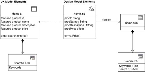
UX model screen compartments can also be realized by specific Web page elements in the design model. The implementation of the screen is responsible for including the separate and distinct JSPs that map to the compartments that make up the screen. Figure 11-20 shows a screen definition for an application home page, which is, by the way, navigable from any other page in the system, most likely from the link in the shared banner compartment.
Figure 11-20. Design model mappings with UX model, including «screen compartment» mappings
As mentioned in Chapter 9, The User Experience, the UX model forms a contract between the information architect and the rest of the UX team and the engineering team. The UX team is responsible for assembling a functional, good-looking application. The engineering team, on the other hand, is more interested in providing access to business state and behavior and in processing new user input.
It has been my experience that traditionally, these two teams don't always play well together. In fact, in several organizations that I've visited, these two teams were located in separate buildings! Very often, one team will make a change that affects the other team, but that realization won't be noticed until far too late in the process. I've noticed a natural tendency for each of these groups of people to claim ownership of the entire Web page or screen, expecting the other team to miraculously keep up and to respond to hastily made changes via ESP or other supernatural means. A formal contract can help set expectations and enable these two teams to work together more effectively.
The way the contract works is that for each defined screen with dynamic content, the engineering team agrees to provide a mechanism for the UX team to easily and simply get the values of the content as defined in the UX model. If possible, the mechanism should use the names used in the screen definition. Whenever the UX team needs to add or to remove content items, the UX model is updated, and engineering is notified to confirm the change. Likewise, if engineering needs to change content items, the model is updated, and the change must be coordinated with the UX team.
Periodically, the two teams' work needs to be integrated and tested. Ideally, the mechanism and architecture for providing access to dynamic content in the scripted pages should allow easy integrations. One of the simplest ways to provide access to named content is to define a server-side scripting variable for each dynamic content item. In Figure 11-21, a simple mapping is shown between a screen class and a JavaServer Page, with each dynamic content item having a scripting variable counterpart with a similar page. Some mandatory initialization code at the top of the page could set the values for the specific instance. In good designs, the code is minimal; ideally, making a single call to an external object would make the least impact to any construction code in the page itself. The UX team would then be able to use and to place the content anywhere in the HTML. The goal is to have the UX team own the HTML in the Web page and to let the engineering team own the API to get to the content.
Figure 11-21. Design model implementing UX model contract
This allows the two teams to work relatively independently. The UX team can develop the HTML and work with server-side scripts, under the assumption that access to certain named content is available. The engineering teams work with very simple and most likely ugly Web page skeletons during coding/debugging cycles. In fact, these simple Web pages are usually easier to test for accurate content because there is no attempt to make it look good. Whenever I build a Web application, I always start this way. Even late in the development process, when the completed HTML is available, I still append to each page the original engineering page stubs as a debug mechanism.[7]
[7] I used a similar technique to provide debug information in the Number Store Reference application (see Appendix B).
In the .NET framework, the development environment makes it easy to bind user interface fields with database fields. If this is the target architecture, mappings to the UX model should include dependencies drawn between UX model screens and logical data model classes.
Another option I like to use in JSP-based applications is custom tags. It is possible to create custom HTML-like tags that can be used in JSP. I like this option because it keeps my JSPs looking like HTML, not a complicated mix of HTML and Java code. The Glossary reference application (Appendix E) uses custom tags and is discussed in the next chapter in more detail.
Overview of Modeling and Web-Related Technologies
- What This Book Is About
- Role of Modeling
- Role of Process
- Influences of Architecture
- Web Application Basics
- HTTP
- HTML
- Web Applications
- Summary
- Discussion
- Activities
- Dynamic Clients
- Document Object Model
- Scripting
- JavaScript Objects
- Custom JavaScript Objects
- Events
- Java Applets
- ActiveX/COM
- Summary
- Discussion
- Activities
- Beyond HTTP and HTML
- Distributed Objects
- XML
- Web Services
- Summary
- Discussion
- Activities
- Security
- Types of Security Risk
- Technical Risk
- Server-Side Risks
- Client-Side Risks
- Security Strategies
- Modeling Secure Systems
- Summary
- Discussion
- Activities
Building Web Applications
- Building Web Applications
- The Process
- Overview of Software Development
- Software Development for Web Applications
- The Artifacts
- Summary
- Discussion
- Activities
- Defining the Architecture
- Architectural Viewpoints
- Architecture Activities
- Web Application Presentation Tier: Architectural Patterns
- Summary
- Discussion
- Activities
- Requirements and Use Cases
- The Vision
- Requirements
- Glossary
- Gathering and Prioritizing Requirements
- Use Cases
- The Use Case Model
- The User Experience
- Summary
- Discussion
- Activities
- The User Experience
- Artifacts of the UX Model
- UX Modeling with UML
- Summary
- Activities
- Analysis
- Iteration
- Analysis Model Structure
- UX Model Mapping
- Architecture Elaboration
- Summary
- Discussion
- Activities
- Design
- Web Application Extension for UML
- Designing Web Applications
- Mapping to the UX Model
- Integrating with Content Management Systems
- Guidelines for Web Application Design
- Summary
- Discussion
- Activities
- Advanced Design
- HTML Frames
- Advanced Client-Side Scripting
- Virtual and Physical HTTP Resources
- JavaServer Page Custom Tags
- Summary
- Discussion
- Activities
- Implementation
- Number Store Main Control Mechanism
- Glossary Application Tag Libraries
- Summary
- Discussion
- Activities
- Overview
- HTML to UML
- UML to HTML
- Mapping Web Elements to UML, and Vice Versa
- Vision
- Background
- Requirements and Features
- Software Architecture Document
- Sample Screen Shots
- Controlled Controllers Pattern
- Use Case View
- Analysis Model Classes
- Analysis Model Collaborations
- Master Template Pattern
- Overview
- Use Case View
- Logical View
- Glossary Application
- Requirements and Use Case Model
- User Experience Model
- Design Model
- Sample Screen Shots
EAN: 2147483647
Pages: 141
