General Packet Radio Service Tunneling Protocol
The General Packet Radio Service (GPRS) is a new carrier service for Global System for Mobile Communication (GSM) that enhances and simplifies wireless access to packet data networks. GPRS architecture uses a radio-packet technique to transfer user data packets in an efficient way between GSM mobile stations and external data networks. The GPRS Tunneling Protocol (GTP) allows multiprotocol packets to be tunneled through a GPRS backbone.
Figure 8-3 illustrates a basic representation of the GPRS architecture.
Figure 8-3. GPRS Architecture Example
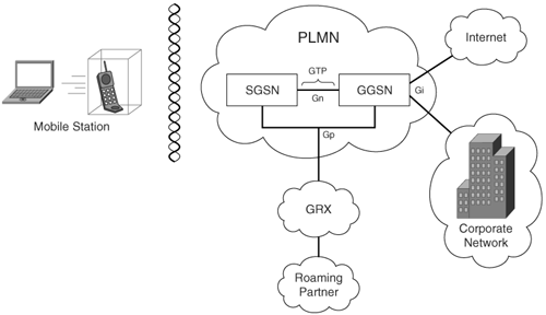
Figure 8-3 shows a mobile station (MS) logically connected to an SGSN. The SGSN provides data services to the MS. The SGSN is logically connected to a GGSN via GTP. If the GTP tunnel connection is over the same Public Land Mobile Network (PLMN), the interface connecting the tunnel is called the Gn interface. Connections between two different PLMNs are known as the Gp interfaces. The GGSN acts as a gateway to external networks such as the Internet or the corporate network via the Gi interface. In other words, the interface between a GGSN and an SGSN is called Gn, whereas the interface between the GGSN and an external data network is called Gi. GTP encapsulates data from the mobile station and controls the establishment, movement, and deletion of tunnels between SGSN and GGSN in roaming scenarios.
There are two versions of GTP:
- GTPv0
- GTPv1
GTPv0
In GTPv0, the GPRS mobile stations are connected to a SGSN without knowing GTP. A Packet Data Protocol (PDP) context is identified by the tunnel identifier (TID), which is a combination of the International Mobile Subscriber Identity (IMSI) and Network Service Access Point Identifier (NSAPI). The mobile stations can have up to 15 NSAPIs each. This allows the mobile stations to create multiple PDP contexts with different NSAPIs. These NSAPIs are based on application requirements for different QoS levels.
The common transport protocol for signaling messages for GTPv0 and v1 is UDP. GTPv0 can allow the use of TCP for the transport protocol data units (TPDUs). The Cisco ASA only supports UDP. The UDP destination port for requests is port 3386.
Figure 8-4 illustrates call flow and the signaling messages involved for GTPv0.
Figure 8-4. GTPv0 Call Flow
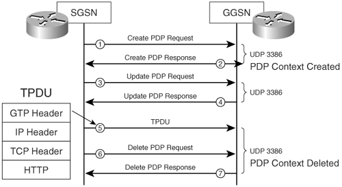
The following is the sequence of events in the call flow shown in Figure 8-4:
- The SGSN sends a create PDP request to the GGSN.
- The PDP context is created and the GGSN sends a PDP response back to the SGSN.
- The SGSN sends an update PDP request message to the GGSN.
- The GGSN replies back.
- TPDUs are sent by the SGSN. (Figure 8-4 shows a sample of the TPDU as seen by the Cisco ASA inspection engine.)
- The SGSN sends a request to delete the PDP context.
- The PDP context is deleted and the GGSN sends its deletion response.
GTPv1
GTPv1 supports primary and secondary contexts for mobile stations. The primary context is identified with an IP address. Secondary contexts are created sharing the IP address and other parameters already associated with the primary context. The advantage of this technique is that the mobile station is able to initiate a connection to a context with different QoS requirements, while sharing the IP address obtained for the primary context.
GTPv1 uses UDP port 2123 for requests and UDP port 2152 for data transfer.
Figure 8-5 illustrates call flow and the signaling messages involved for GTPv1.
Figure 8-5. GTPv1 Call Flow
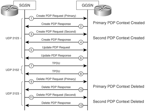
The following is the sequence of events in the call flow shown in Figure 8-5:
- The SGSN sends a PDP context create request for the primary PDP context.
- The primary context is created and the GGSN sends its response.
- The SGSN sends a PDP context create request for the second PDP context.
- The second context is created and the GGSN sends its response.
- The SGSN sends a PDP update request to the GGSN.
- The GGSN replies back with a PDP update response.
- TPDU (data packets) are sent to the GGSN.
- TPDU (data packets) are sent to the SGSN.
- The SGSN sends a request to delete the primary PDP context.
- The primary PDP context is deleted and the GGSN sends its response.
- The SGSN sends a request to delete the second PDP context.
- The second PDP context is deleted and the GGSN sends its response.
Figure 8-6 shows how the Cisco ASA can be positioned between GPRS networks.
Figure 8-6. Cisco ASA in GPRS Network
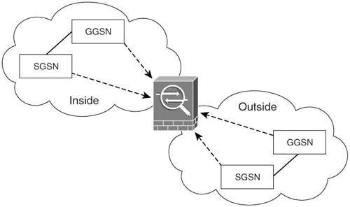
In Figure 8-6, the Cisco ASA is positioned between two GPRS PLMNs. This exemplifies how a mobile station may move from its home PLMN (HPLMN) to a visited PLMN (VPLMN) and communication will still be possible through the Cisco ASA. The Cisco ASA inspects all traffic between the respective SGSNs and GGSNs.
Configuring GTP Inspection
To enable GTP inspection, use the inspect gtp command. You can also associate a GTP map to create a more customizable configuration. This provides granular control of various GTP parameters and filtering options.
Note
GTP inspection is not supported with NAT or PAT. GTP inspection requires a special license from Cisco. For more information about licensing go to Cisco's website at www.cisco.com/go/nac
A GTP map can be created using the gtp-map command followed by the name of the map. Example 8-10 demonstrates how the Cisco ASA is configured with a GTP map, called mygtpmap, to enforce different restrictions.
Example 8-10. GTP Inspection Example
gtp-map mygtpmap

 tunnel-limit 1000

 request-queue 500

class-map inspection_default

 match default-inspection-traffic

policy-map asa_global_fw_policy

 class inspection_default

 inspect gtp mygtpmap
In Example 8-10, the Cisco ASA only allows a maximum of 1000 GTP tunnels and only allows a maximum of 500 requests to be queued. The GTP map is mapped to the default policy map under the default inspection class.
Table 8-4 lists all the subcommands available to configure under a GTP map.
|
Subcommand |
Description |
|---|---|
|
description |
Used to enter a brief description of the GTP map. |
|
drop |
Used to drop messages based on three different keywords:
|
|
mcc |
Used to specify a three-digit mobile country code. Values can be from 000 to 999. Country codes with one or two digits will be prepended with zeros. |
|
message-length |
Used to specify the minimum and maximum message length. |
|
permit |
Used to enable the Cisco ASA to allow packets with errors. |
|
request-queue |
Used to specify the maximum requests allowed on the queue. |
|
timeout |
Used to configure the idle timeout for the following:
|
|
tunnel-limit |
Used to configure the maximum tunnels allowed. |
Part I: Product Overview
Introduction to Network Security
- Introduction to Network Security
- Firewall Technologies
- Intrusion Detection and Prevention Technologies
- Network-Based Attacks
- Virtual Private Networks
- Summary
Product History
- Product History
- Cisco Firewall Products
- Cisco IDS Products
- Cisco VPN Products
- Cisco ASA All-in-One Solution
- Summary
Hardware Overview
Part II: Firewall Solution
Initial Setup and System Maintenance
- Initial Setup and System Maintenance
- Accessing the Cisco ASA Appliances
- Managing Licenses
- Initial Setup
- IP Version 6
- Setting Up the System Clock
- Configuration Management
- Remote System Management
- System Maintenance
- System Monitoring
- Summary
Network Access Control
- Network Access Control
- Packet Filtering
- Advanced ACL Features
- Content and URL Filtering
- Deployment Scenarios Using ACLs
- Monitoring Network Access Control
- Understanding Address Translation
- DNS Doctoring
- Monitoring Address Translations
- Summary
IP Routing
Authentication, Authorization, and Accounting (AAA)
- Authentication, Authorization, and Accounting (AAA)
- AAA Protocols and Services Supported by Cisco ASA
- Defining an Authentication Server
- Configuring Authentication of Administrative Sessions
- Authenticating Firewall Sessions (Cut-Through Proxy Feature)
- Configuring Authorization
- Configuring Accounting
- Deployment Scenarios
- Troubleshooting AAA
- Summary
Application Inspection
- Application Inspection
- Enabling Application Inspection Using the Modular Policy Framework
- Selective Inspection
- Computer Telephony Interface Quick Buffer Encoding Inspection
- Domain Name System
- Extended Simple Mail Transfer Protocol
- File Transfer Protocol
- General Packet Radio Service Tunneling Protocol
- H.323
- HTTP
- ICMP
- ILS
- MGCP
- NetBIOS
- PPTP
- Sun RPC
- RSH
- RTSP
- SIP
- Skinny
- SNMP
- SQL*Net
- TFTP
- XDMCP
- Deployment Scenarios
- Summary
Security Contexts
- Security Contexts
- Architectural Overview
- Configuration of Security Contexts
- Deployment Scenarios
- Monitoring and Troubleshooting the Security Contexts
- Summary
Transparent Firewalls
- Transparent Firewalls
- Architectural Overview
- Transparent Firewalls and VPNs
- Configuration of Transparent Firewall
- Deployment Scenarios
- Monitoring and Troubleshooting the Transparent Firewall
- Summary
Failover and Redundancy
- Failover and Redundancy
- Architectural Overview
- Failover Configuration
- Deployment Scenarios
- Monitoring and Troubleshooting Failovers
- Summary
Quality of Service
- Quality of Service
- Architectural Overview
- Configuring Quality of Service
- QoS Deployment Scenarios
- Monitoring QoS
- Summary
Part III: Intrusion Prevention System (IPS) Solution
Intrusion Prevention System Integration
- Intrusion Prevention System Integration
- Adaptive Inspection Prevention Security Services Module Overview (AIP-SSM)
- Directing Traffic to the AIP-SSM
- AIP-SSM Module Software Recovery
- Additional IPS Features
- Summary
Configuring and Troubleshooting Cisco IPS Software via CLI
- Configuring and Troubleshooting Cisco IPS Software via CLI
- Cisco IPS Software Architecture
- Introduction to the CIPS 5.x Command-Line Interface
- User Administration
- AIP-SSM Maintenance
- Advanced Features and Configuration
- Summary
Part IV: Virtual Private Network (VPN) Solution
Site-to-Site IPSec VPNs
- Site-to-Site IPSec VPNs
- Preconfiguration Checklist
- Configuration Steps
- Advanced Features
- Optional Commands
- Deployment Scenarios
- Monitoring and Troubleshooting Site-to-Site IPSec VPNs
- Summary
Remote Access VPN
- Remote Access VPN
- Cisco IPSec Remote Access VPN Solution
- Advanced Cisco IPSec VPN Features
- Deployment Scenarios of Cisco IPSec VPN
- Monitoring and Troubleshooting Cisco Remote Access VPN
- Cisco WebVPN Solution
- Advanced WebVPN Features
- Deployment Scenarios of WebVPN
- Monitoring and Troubleshooting WebVPN
- Summary
Public Key Infrastructure (PKI)
- Public Key Infrastructure (PKI)
- Introduction to PKI
- Enrolling the Cisco ASA to a CA Using SCEP
- Manual (Cut-and-Paste) Enrollment
- Configuring CRL Options
- Configuring IPSec Site-to-Site Tunnels Using Certificates
- Configuring the Cisco ASA to Accept Remote-Access VPN Clients Using Certificates
- Troubleshooting PKI
- Summary
Part V: Adaptive Security Device Manager
Introduction to ASDM
- Introduction to ASDM
- Setting Up ASDM
- Initial Setup
- Functional Screens
- Interface Management
- System Clock
- Configuration Management
- Remote System Management
- System Maintenance
- System Monitoring
- Summary
Firewall Management Using ASDM
- Firewall Management Using ASDM
- Access Control Lists
- Address Translation
- Routing Protocols
- AAA
- Application Inspection
- Security Contexts
- Transparent Firewalls
- Failover
- QoS
- Summary
IPS Management Using ASDM
- IPS Management Using ASDM
- Accessing the IPS Device Management Console from ASDM
- Configuring Basic AIP-SSM Settings
- Advanced IPS Configuration and Monitoring Using ASDM
- Summary
VPN Management Using ASDM
- VPN Management Using ASDM
- Site-to-Site VPN Setup Using Preshared Keys
- Site-to-Site VPN Setup Using PKI
- Cisco Remote-Access IPSec VPN Setup
- WebVPN
- VPN Monitoring
- Summary
Case Studies
EAN: 2147483647
Pages: 231
- Chapter II Information Search on the Internet: A Causal Model
- Chapter III Two Models of Online Patronage: Why Do Consumers Shop on the Internet?
- Chapter IV How Consumers Think About Interactive Aspects of Web Advertising
- Chapter VIII Personalization Systems and Their Deployment as Web Site Interface Design Decisions
- Chapter XVII Internet Markets and E-Loyalty
- The Four Keys to Lean Six Sigma
- Key #1: Delight Your Customers with Speed and Quality
- Key #3: Work Together for Maximum Gain
- Making Improvements That Last: An Illustrated Guide to DMAIC and the Lean Six Sigma Toolkit
- The Experience of Making Improvements: What Its Like to Work on Lean Six Sigma Projects
