Routing on the Concentrator
Because concentrators are used in medium-to-large networks and these networks are composed of many subnets, you'll need to set up routing on your concentrator. The concentrator supports two types of routing: static and dynamic. You can create specific static routes or default routes. In addition, the concentrator supports two dynamic routing protocols: RIP and OSPF. The remaining subsections will discuss the configuration of routing on the concentrator.
Static Routing
Global routing configurations are performed on the IP Routing screen, which is accessed by clicking Configuration > System > IP Routing. The concentrator supports two types of static routes: default and static. Each is discussed in turn in the following sections.
Default Route
A default route is a gateway of last resort: if a specific route is not found in the concentrator's routing table to reach a destination, the default route is used. To define a default route, click the Default Gateways hyperlink, which takes you to the screen in Figure 10-4.
Figure 10-4. Default Route
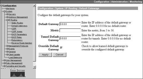
Within the screen, there are several parameters, as follows:
- The Default Gateway parameter allows you to assign an IP address of the next hop to reach the destination network. This is typically a router or firewall.
- The Metric parameter allows you to specify a metric for the default gateway. This is used when you need to create a primary and backup default route, where a metric of 1 specifies the primary default route.
- The Tunnel Default Gateway parameter allows you to specify a different IP address to use for the default gateway of VPN sessionsnon-VPN traffic would use the default gateway specified in the Default Gateway parameter.
- The Override Default Gateway check box allows you to use a dynamically learned default gateway instead of the one hard-coded on this screen: this could be one learned via DHCP if the concentrator is a DHCP client or one learned via RIP or OSPF.
You would click the Apply button to accept your configuration.
Static Routes
Static routes typically are used when you aren't using a dynamic routing protocol to reach networks. To create a static route, from the IP Routing screen click the Static Routes hyperlink. This screen will display static routes you have configured. To create a static route, click the Add button, taking you to the screen in Figure 10-5.
Figure 10-5. Static Routes
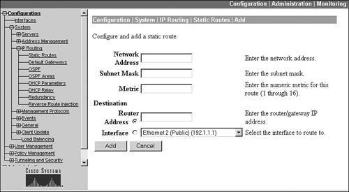
Within the screen, there are several parameters, as follows:
- The Network Address and Subnet Mask parameters allow you to enter the static route for the destination.
- The Metric parameter, which is required, assigns a metric to the static route: this can be from 116 and can be used to weight the route if you need to create more than one static route for the same destination network for redundancy.
- The Destination parameter can be one of two values: Router Address or Interface. If you choose the Router Address radio button, you'll need to enter the IP address of the next-hop address of the Layer-3 device that the concentrator will use to reach the destination network. You typically would choose this option when you know the IP address of the next hop. Otherwise, if you choose the Interface radio button, you'll need to use the drop-down selector to choose the interface the concentrator should use to reach the destination network. You typically would choose this option when you don't know the IP address of the next hop, because the concentrator is acquiring its addressing information dynamically via DHCP on the interface.
Last, click the Add button to add the static route.
RIP Routing Protocol
RIP is one of the two dynamic routing protocols that the concentrator supports. Both RIPv1 and RIPv2 are supported, in addition to a compatibility mode. The configuration of RIP is done on the concentrator's interfaces: Configuration > Interfaces. From here, click the hyperlink of the interface; for example, the private interface.
On the Interface screen are four tabs at the top: to enable RIP, click the RIP tab, which displays the screen in Figure 10-6. This is the private interface of the concentrator, for which the default configuration is that inbound RIPv1/2 updates are accepted, but no RIP updates are sent out of the interface.
Figure 10-6. RIP Configuration
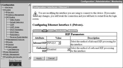
In Figure 10-6, the Inbound RIP parameter allows you to specify whether or not you want to learn RIP routes from neighboring RIP routers off this interface. This parameter can be set to "Disabled," "RIPv1 only," "RIPv2 only," or "RIPv2/v1." The Outbound RIP parameter allows you to specify whether or not you want to send RIP updates out of this interface.
Note
Even though RIPv2 is supported, RIPv2 authentication is not; however, other features such as variable-length subnet masks (VLSM) and multicasting are. If you create a default route on the concentrator, it is not propagated via RIP on an interface; however, static routes that you configure on the concentrator are redistributed automatically into RIP and advertised out of interfaces configured for outbound RIP. This also applies to static routes learned via reverse route injection (RRI).
Also, inbound and outbound RIP on the public interface is denied by the public interface filterto allow inbound and outbound RIP, you must add these rules to the public interface filter. If you have filters on other concentrator interfaces, you'll need to add RIP rules to these also.
OSPF Routing Protocol
The second dynamic routing protocol supported by the concentrator is OSPF (defined in RFC 2328). The configuration of OSPF is slightly different than RIP. First, you must enable OSPF, assign the concentrator a router ID, and define the areas the concentrator is connected to. These tasks are performed from the IP Routing screen. Second, as with RIP, you must turn on OSPF on the concentrator's interface(s).
OSPF: IP Routing Screen
The IP Routing screen has two OSPF hyperlinks:
- OSPF
- OSPF Areas
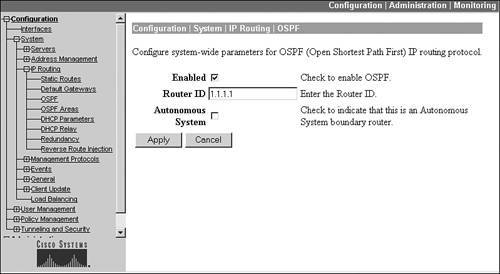
If you click the OSPF hyperlink, you're taken to the screen shown in Figure 10-7. To enable OSPF, click the Enabled check box. You must assign your concentrator a unique router ID that identifies the concentrator in the OSPF network. Normally, an IP address on one of the concentrator's interfaces is used. Once you assign the ID, you can't change it unless you first disable OSPF. The Autonomous System check box needs to be checked if the concentrator is going to be an autonomous system boundary router (ASBR). By enabling this, you can take RIP or static routes in the concentrator's routing table and advertise these into the OSPF process: this is necessary if you're using RRI. Click the Apply button to activate your changes.
Figure 10-7. OSPF Routing Process Configuration
If you click the OSPF Areas hyperlink from the IP Routing screen, you are taken to a screen that displays the areas the concentrator is connected to. To add an area, click the Add button; by default, area 0 (0.0.0.0) already exists on the screen.
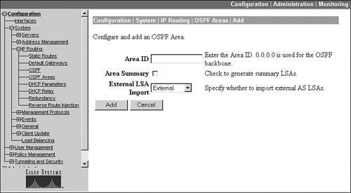
Figure 10-8 shows an example of adding an area by clicking the Add button. At the top of the screen, enter the area number in the Area ID text box. Below this, if the concentrator is an area border router (ABR) and you want to generate summarized LSAs, click the Area Summary check box. To import routes (either RIP or static) into the concentrator's OSPF process, change the External LSA Import drop-down selector to "External."
Figure 10-8. OSPF Area Configuration
OSPF: Interfaces
Once you have configured OSPF globally, you must enable it on your concentrator's interface or interfaces where you want to learn or share OSPF routes. Go to the Configuration > Interfaces screen and click the hyperlink of the interface; then click the OSPF tab. Part of this screen is shown in Figure 10-9.
Figure 10-9. OSPF Interface Configuration
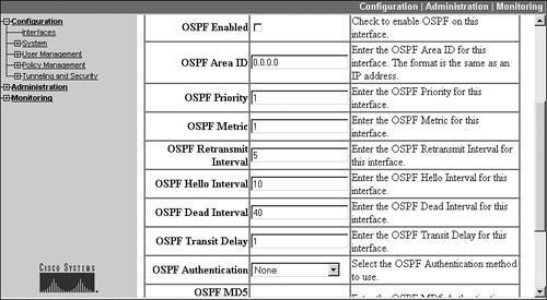
To enable OSPF on the interface, select the OSPF Enabled check box. The only other required parameter is the OSPF area that the interface is associated with: this value defaults to area 0 (0.0.0.0). The other parameters are optional.
One security function you might want to enable in the screen shown in Figure 10-9 is OSPF authentication, which allows you to authenticate routing updates you receive or send. To enable this, set the OSPF Authentication parameter to "MD5," change the OSPF MD5 Authentication Key ID parameter to the correct key number, and set the OSPF Password to the key value used for creating the MD5 hashed output (digital signature). The key number and password will need to match what the other routers are using on the segment connected to this interface.
Note
Also, inbound and outbound OSPF on the public interface are denied by the public interface filterto allow inbound and outbound OSPF, you must add these rules to the public interface filter. If you have filters on other concentrator interfaces, you'll need to add OSPF rules to these also.
Once you've configured routing on the concentrator, you can view the concentrator's routing table by going to the Monitoring > Routing Table.
Tip
If you're using OSPF as a routing protocol in your network and your internal Layer-3 devices are not seeing RRI routes from your concentrator, make sure that RRI has been enabled on the concentrator and that you have configured the concentrator as an ASBR for OSPF and have allowed OSPF external routes.
Part I: VPNs
Overview of VPNs
- Overview of VPNs
- Traffic Issues
- VPN Definition
- VPN Components
- VPN Designs
- VPN Implementations
- VPNs: Choosing a Solution
- Summary
VPN Technologies
IPsec
PPTP and L2TP
SSL VPNs
Part II: Concentrators
Concentrator Product Information
- Concentrator Product Information
- Concentrator Models
- Concentrator Modules
- Concentrator Features
- Introduction to Accessing a Concentrator
- Summary
Concentrator Remote Access Connections with IPsec
- Concentrator Remote Access Connections with IPsec
- Controlling Remote Access Sessions to the Concentrator
- IPsec Remote Access
- Network Access Control (NAC) for IPsec and L2TP/IPsec Users
- Summary
Concentrator Remote Access Connections with PPTP, L2TP, and WebVPN
- Concentrator Remote Access Connections with PPTP, L2TP, and WebVPN
- PPTP and L2TP Remote Access
- WebVPN Remote Access
- Summary
Concentrator Site-to-Site Connections
- Concentrator Site-to-Site Connections
- L2L Connectivity Example
- ISAKMP/IKE Phase 1 Preparation
- Adding Site-to-Site Connections
- Address Translation and L2L Sessions
- Summary
Concentrator Management
- Concentrator Management
- Bandwidth Management
- Routing on the Concentrator
- Chassis Redundancy
- Administration Screens
- Summary
Verifying and Troubleshooting Concentrator Connections
- Verifying and Troubleshooting Concentrator Connections
- Concentrator Tools
- Troubleshooting Problems
- Summary
Part III: Clients
Cisco VPN Software Client
- Cisco VPN Software Client
- Cisco VPN Client Overview
- Cisco VPN Client Interface
- IPsec Connections
- VPN Client GUI Options
- VPN Client Software Updates
- VPN Client Troubleshooting
- Summary
Windows Software Client
- Windows Software Client
- Windows Client
- Configuring the Windows VPN Client
- Configuring the VPN 3000 Concentrator
- Microsoft Client Connections
- Troubleshooting VPN Connections
- Summary
3002 Hardware Client
- 3002 Hardware Client
- Overview of the 3002 Hardware Client
- Initial Access to the 3002
- Authentication and Connection Options
- Connection Modes
- Administrative Tasks
- Summary
Part IV: IOS Routers
Router Product Information
Router ISAKMP/IKE Phase 1 Connectivity
- Router ISAKMP/IKE Phase 1 Connectivity
- IPsec Preparation
- ISAKMP/IKE Phase 1 Policies
- ISAKMP/IKE Phase 1 Device Authentication
- Monitoring and Managing Management Connections
- Routers as Certificate Authorities
- Summary
Router Site-to-Site Connections
- Router Site-to-Site Connections
- ISAKMP/IKE Phase 2 Configuration
- Viewing and Managing Connections
- Issues with Site-to-Site Connections
- Summary
Router Remote Access Connections
- Router Remote Access Connections
- Easy VPN Server
- Easy VPN Remote
- IPsec Remote Access and L2L Sessions on the Same Router
- WebVPN
- Summary
Troubleshooting Router Connections
- Troubleshooting Router Connections
- ISAKMP/IKE Phase 1 Connections
- ISAKMP/IKE Phase 2 Connections
- New IPsec Troubleshooting Features
- Fragmentation Problems
- Summary
Part V: PIX Firewalls
PIX and ASA Product Information
- PIX and ASA Product Information
- PIX Deployment Scenarios
- PIX and ASA Feature and Product Overview
- Summary
PIX and ASA Site-to-Site Connections
- PIX and ASA Site-to-Site Connections
- ISAKMP/IKE Phase 1 Management Connection
- ISAKMP/IKE Phase 2 Data Connections
- L2L Connection Examples
- Summary
PIX and ASA Remote Access Connections
- PIX and ASA Remote Access Connections
- Easy VPN Server Support for 6.x
- Easy VPN Remote Support for 6.x
- Easy VPN Server Support for 7.0
- Summary
Troubleshooting PIX and ASA Connections
- Troubleshooting PIX and ASA Connections
- ISAKMP/IKE Phase 1 Connections
- ISAKMP/IKE Phase 2 Connections
- Summary
Part VI: Case Study
Case Study
Index
EAN: 2147483647
Pages: 178
