Summary
| < Free Open Study > |
ISDN Development, Components, and MechanicsOnce upon a time, in the early days of the public telephone network, telephone users were began replacing the analog circuits in the core of their networks with packet-based digital signals. Analog circuits still were delivered to the telephone users at the local loop level. ISDN delivers the digital circuits directly to the customers, enabling them to carry a wide variety of traffic over the network. Therefore, ISDN enables users to carry voice, video, data, and other traffic over the existing telephone wiring. When ISDN became an emerging technology, it was envisioned to become the leading worldwide digital network technology, providing access to everyone. Now, with the emergence of xDSL and cable modems, ISDN is losing favor with the home access market. However, ISDN is still a major player in the business market, where it is used to back up primary links and where PRI/E1s are used to carry data and V.90 remote dial-in access. It is also more readily available than DSL and cable, allowing the majority of home users who fail to qualify for cable or DSL to purchase ISDN service. A standards committee was developed in 1984 to coordinate the ISDN movement, called the International Telephone and Telegraph Consultative Committee (CCITT), now known as the International Telecommunications Union (ITU). The ITU organizes the ISDN protocols according to three general topic areas:
Debugging Q.921 and Q.931 sometimes can be useful for troubleshooting ISDN connectivity problems, and this is discussed in more detail later in the chapter. The major advantage of ISDN is that it allows multiple digital channels to operate simultaneously over one circuit. Currently, there are three types of ISDN channels:
Cisco supports the following two ISDN interface types, which combine the channel types in the preceding list:
ISDN Components and Reference PointsTo access the ISDN network, customer premises equipment (CPE), which is the local terminating equipment, is used. This equipment performs the functions needed for properly connecting to the ISDN network. The following describes the types of ISDN CPE options:
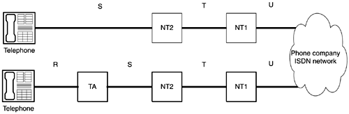
Because CPE can include one or more of these functions, the way in which they connect to the other ISDN devices can vary. Because of this, the ISDN standards refer to these various interfaces as reference points. The reference points simply define the logical points between the previous CPE groups. Figure 7-1 shows the reference points, which are described as follows: Figure 7-1. ISDN Reference Points
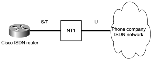
In most implementations for BRI users, an NT2 is not used and usually is found only in PBXs. In this case, the CPE-to-carrier interface is referred to as the S/T interface. Generally, routers come with an integrated S/T ISDN interface, so the reference points would look like they do in Figure 7-2. Figure 7-2. ISDN Reference Points for a Router with an Integrated S/T ISDN Interface Additionally, Cisco routers can be purchased with an S/T interface and integrated NT1, so reference points S, T, and U would all be incorporated into the BRI/PRI interface of the Cisco router. In North America, all ISDN lines are connected to the ISDN switch at the local central office (CO) through a U interface. This U interface requires network termination to convert it into an S/T interface that actually connects to your end equipment. An NT-1 is a separate unit that serves this function and also provides power to your ISDN line. In Europe, the NT-1 is included in telco-provisioned ISDN lines, so all you need is the S/T interface. When working with Cisco routers, it is important to determine whether the unit has an S/T interface, which will require an external NT-1, or a U interface with a built-in NT-1. Check your hardware manual to determine whether you have the proper equipment. ISDN LayersISDN deals with Layers 1, 2, and 3 of the OSI reference model. ISDN connectivity works only if all three of these layers are operational. Layer 1 is the physical layer, dealing with the physical connections between the router and the ISDN circuit. Layer 2, the data link layer, deals with the Q.921 protocol on the D channel and the encapsulation options for each B channel (HDLC and PPP). Q.921 handles the signaling between the router ISDN interface and the ISDN switch. Layer 3, the network layer, includes the Q.931 protocol over the D channel and network layer protocols (IP, IPX, AppleTalk, and so on) over the B channels. Q.931 handles call setup messages between the calling and called parties. It is important to fully understand the various protocols that operate over the D and B channels when configuring and troubleshooting ISDN. ISDN Encapsulation OptionsISDN routers can support both PPP and HDLC encapsulations . HDLC is the default encapsulation, but the vast majority of ISDN routers use PPP. The main reason that PPP is chosen over HDLC is because HDLC cannot use both B channels simultaneously. With HDLC, both B channels can be up, but one channel is used to send and the other is used to receive traffic. Each B channel has the capability to provide full duplex (send and receive at the same time), so by using HDLC, you are essentially cutting the possible data rate over the link in half. PPP was covered in Chapter 4. |
| < Free Open Study > |
EAN: 2147483647
Pages: 283