MPLS TE Theory
This section introduces you to the theoretical nuances in the implementation of MPLS TE. The primary topics covered will be the components of MPLS TE as well as RSVP and its function in the implementation of MPLS TE.
MPLS TE Overview
In a traditional IP forwarding paradigm, packets are forwarded on a per-hop basis where a route lookup is performed on each router from source to destination. As cited earlier, the destination-based forwarding paradigm leads to suboptimal use of available bandwidth between a pair of routers in the service provider network. Predominantly, the suboptimal paths are under-utilized in IP networks. To avoid packet drops due to inefficient use of available bandwidth and to provide better performance, TE is employed to steer some of the traffic destined to follow the optimal path to a suboptimal path to enable better bandwidth management and utilization between a pair of routers. TE, hence, relieves temporary congestion in the core of the network on the primary or optimal cost links. TE maps flows between two routers appropriately to enable efficient use of already available bandwidth in the core of the network. The key to implementing a scalable and efficient TE methodology in the core of the network is to gather information on the traffic patterns as they traverse the core of the network so that bandwidth guarantees can be established. As illustrated in Figure 9-2, TE tunnels, Tunnel1 and Tunnel2, can be configured on PE1-AS1 that can map to separate paths (PATH1, PATH2), enabling efficient bandwidth utilization.
TE tunnels configured on routers are unidirectional. Therefore, to implement bidirectional TE deployment between routers PE1-AS1 and PE2-AS1 in Figure 9-2, a pair of tunnels must also be configured on PE2-AS1 in addition to Tunnel1 and Tunnel2 configured on PE1-AS1. In an MPLS network, all pertinent tunnel configurations are always performed or provider edge (PE) routers. The TE tunnels or LSPs will be used to link the edge routers across the core of the service provider network.
MPLS TE can also map to certain classes of traffic versus destinations. If Customer A CE routers are connected into the SP network using OC3 links versus Customer B connecting into the SP network using a 64 K dialup link, preferential treatment can be configured on TE tunnels so that TE Tunnel1 can carry Customer A traffic and Tunnel2 can carry Customer B traffic. This is shown in Figure 9-3. Also note that Figure 9-3 illustrates tunnels configured on both PE1-AS1 and PE2-AS1.
Figure 9-3. TE Tunnels Based on Customer CoS

TE tunnels are, thus, data flows between a specific source and destination that might have properties or attributes associated with them. The attributes associated with a tunnel, in addition to the ingress (headend) and egress (tailend) points of the network, can include the bandwidth requirements and the CoS for data that will be forwarded utilizing this tunnel. Traffic is forwarded along the path defined as the TE tunnel by using MPLS label switching. Hence, TE tunnels are assigned specific label switched paths (LSPs) in the network from source to destination, which are usually PE routers. MPLS LSPs have a one-to-one mapping with TE tunnels, and TE tunnels are not bound to a specific path through the SP network to a destination PE router. Unless configured explicitly, TE tunnels can reroute packets via any path through the network associated with an MPLS LSP. This path might be defined by the IGP used in the core, which are discussed in the section on MPLS TE extensions.
The primary reason for the implementation of MPLS TE is to control paths along which traffic flows through a network. MPLS TE also lends itself to a resilient design in which a secondary path can be used when the primary path fails between two routers in a network. Data plane information is forwarded using label switching; a packet arriving on a PE from the CE router is applied labels and forwarded to the egress PE router. The labels are removed at the egress router and forwarded out to the appropriate destination as an IP packet.
OSPF or IS-IS with extensions for TE is used to carry information pertaining to the tunnel configured on a router. The extensions carry information on available resources for building a tunnel, like bandwidth on a link. As a result, a link that does not have the requested resources (like bandwidth) is not chosen to be a part of the LSP tunnel or TE tunnel. Signaling in an MPLS TE environment uses resource reservation protocol (RSVP) with extensions to support TE tunnel features.
The data plane ingress (headend) router in the MPLS domain requires information pertaining to the resource availability on all links capable of being a part of the MPLS TE tunnel. This information is provided by IGPs like OSPF and IS-IS due to the inherent operation of flooding information about links to all routers in the IGP domain. In IS-IS, a new TLV (type 22) has been developed to transmit information pertaining to resource availability and link status in the LS-PDUs. In OSPF, the type 10 LSA provides resource and links status information. When this information is flooded in IGP updates, the ingress (headend) router gathers information on all the available resources in the network along with the topology, which defines tunnels through the network between a set of MPLS-enabled routers.
The inspiration behind MPLS TE is Constraint Based Routing (CBR), which takes into account the possibility of multiple paths between a specific source/destination pair in a network. With CBR, the operation of an IP network is enhanced so the least cost routing can be implemented as well as variables to find paths from a source to destination. CBR requires an IGP, like OSPF or IS-IS, for its operation. CBR is the backbone of the TE tunnel definition and is defined on the ingress routers to the MPLS domain when implementing MPLS TE. Resource availability and link status information are calculated using a constrained SPF calculation in which factors such as the bandwidth, policies, and topology are taken into consideration to define probable paths from a source to destination.
CSPF calculation results with an ordered set of IP addresses that map to next-hop IP addresses of routers forming an LSP, in turn mapping to the TE tunnel. This ordered set is defined by the headend router that is propagated to other routers in the LSP. The intermediate routers, thus, do not perform the function of path selection. RSVP with TE extensions is used to reserve resources in the LSP path as well as label association to the TE tunnel. The operation of RSVP for MPLS TE is introduced in the next section.
RSVP with TE Extensions: Signaling
RSVP reserves bandwidth along a path from a specific source to destination. RSVP messages are sent by the headend router in a network to identify resource availability along the path from a specific source to destination. The headend router is always the source of the MPLS TE tunnel, and the tailend router is the router that functions as the endpoint for the TE tunnel. After the RSVP messages are sent, the status of routers in the path (resource availability) information is stored in the path message as it traverses the network. RSVP, therefore, communicates the requirements of a specific traffic flow to the network and gathers information about whether the requirements can be fulfilled by the network.
The four main messages used in implementation of RSVP for TE are the RSVP PATH message, the RSVP RESERVATION message, RSVP error messages, and RSVP tear messages. In MPLS TE, RSVP is used to ensure and verify resource availability, as well as apply the MPLS labels to form the MPLS TE LSP through the routers in the network:
- RSVP PATH message – Generated by the headend router and is forwarded through the network along the path of a future TE LSP. At each hop, the PATH message checks the availability of requested resources and stores this information. In our network, shown in Figure 9-4, the PATH message is generated by Router PE1-AS1, the headend router, and is forwarded downstream where it checks resource availability at each hop (P1-AS1 and PE2-AS1). The RSVP PATH message functions as a label request in MPLS TE domain. Because all TE domains function with downstream-on-demand label allocation mode, the request to assign a label is generated at the headend router and propagated downstream.
Figure 9-4. RSVP PATH and RESERVATION Messages
- RSVP RESERVATION message – Created by the tailend router in the MPLS TE domain and used to confirm the reservation request that was sent earlier with the PATH messages. In the network depicted in Figure 9-4, PE2-AS1 will generate the RSVP RESERVATION message in response to the PATH message. Therefore, PATH messages function as reservation requests and RESERVATION messages function as reservation confirmations for the availability of requested resources. The RSVP RESERVATION message performs the function of label assignment for a particular LSP mapping to the TE tunnel. As the MPLS domain label allocation and distribution is performed downstream-on-demand, the label mapping to a TE LSP is first generated by the tailend router or egress Edge LSR and then propagated upstream. This process is repeated at each hop upstream where local labels mapping to a TE tunnel are assigned and propagated upstream until the headend router is reached.
- RSVP error messages – In the event of unavailability of the requested resources, the router generates RSVP error messages and sends them to the router from which the request or reply was received. If Router P1-AS1 is unable to accommodate requested resources as defined in the PATH message generated by PE1-AS1 (headend router), the router generates a PATH ERROR (PATHERR) message and sends it to its upstream LSR PE1-AS1, as depicted in Figure 9-5.
Figure 9-5. RSVP PATH Error and RESERVATION Error Messages
If the RSVP PATH message successfully reaches the tailend router, the tailend Router PE2-AS1 generates a RESERVATION message. If in the time lapsed between P1-AS1 receiving the PATH message from PE1-AS1 to receiving the RESERVATION message from PE2-AS1, P1-AS1 identifies a lack of resources to confirm the request, P1-AS1 will send a RESERVATION ERROR (RESVERR) message to its downstream LSR PE2-AS1 denying the reservation, as depicted in Figure 9-5.
- RSVP tear messages – RSVP creates two types of tear messages, namely, the PATH tear message and the RESERVATION tear message. These tear messages clear the PATH or RESERVATION states on the router instantaneously. The process of clearing a PATH or RESERVATION state on a router using tear messages enables the reuse of resources on the router for other requests. The PATH tear messages are usually generated in inter-area LSP creation where the inter-area LSP is not configured to be fast reroutable, and if a link failure occurs within an area, the LSR to which the failed link is directly attached will generate an RSVP PATH error and an RESV tear message to the headend. The headend will then generate an RSVP PATH tear message. The corresponding path option will be marked as invalid for a certain amount of time and the next path option will be immediately evaluated if it exists.
RSVP Operation in MPLS TE
As mentioned earlier, the result of a CSPF or CBR calculation on the headend router is an ordered list of IP addresses that identifies the next hops along the path of the TE tunnel or LSP. This list of routers is computed and is known only to the headend router that is the source of the TE tunnel. Other routers in the domain do not perform a CBR calculation. The headend router provides information to the routers in the TE tunnel path via RSVP signaling to request and confirm resource availability for the tunnel. RSVP with extensions for TE reserves appropriate resources on each LSR in the path defined by the headend router and assigns labels mapping to the TE tunnel LSP.
The RSVP extensions to enable RSVP use for signaling in an MPLS environment to implement TE are defined in Table 9-1. The functions of each of these extensions/objects in the messages are also outlined.
|
Object |
Message |
Function |
|---|---|---|
|
LABEL_REQUEST |
PATH |
Used to request a label mapping to the TE tunnel or LSP; generated by the headend router in the PATH message. |
|
LABEL |
RESERVATION |
Used to allocate labels mapping to the TE tunnel or LSP; generated by the tailend router in the RESERVATION message and propagated upstream. |
|
EXPLICIT_ROUTE |
PATH |
Carried in PATH messages and is used to either request or confirm a specific path/route for the tunnel. |
|
RECORD_ROUTE |
PATH, RESERVATION |
Similar to a record option with ICMP ping. It is added to the PATH or RESERVATION messages to notify the originating node about the actual route/path that the LSP TE tunnel traverses. |
|
SESSION_ATTRIBUTE |
PATH |
Used to define specific session parameters local to the TE LSP tunnel. |
During the path setup process for LSP TE tunnels, RSVP messages containing one or more of these extensions are used to identify the significance of each message type and its contents.
The path message contains the information outlined in Table 9-2.
|
Object |
Message |
|---|---|
|
SESSION |
Defines the source and the destination of the LSP tunnel. Usually identified by IP addresses of corresponding loopback interfaces on headend and tailend routers. |
|
SESSION_ATTRIBUTE |
Defines the characteristics of the specific LSP tunnel, such as the bandwidth requirements and resources that would need to be allocated to the tunnel. |
|
EXPLICIT_ROUTE |
Populated by the list of next hops that are either manually specified or calculated using constraint-based SPF. The previous hop (PHOP) is set to the router's outgoing interface address. The Record_Route (RRO) is populated with the same address as well. |
|
RECORD_ROUTE |
Populated with the local router's outgoing interface address in the path of the LSP tunnel. |
|
SENDER_TEMPLATE |
In addition to the previously mentioned attributes, the sender template object in the path message depicts the interface address that will be used as the LSP-ID for the tunnel. This value is defined by the headend router. |
The steps in the PATH and RESV message propagation in Figure 9-6 are depicted here:
|
Step 1. |
The appropriate values for the fields mentioned in Table 9-1 applied by the headend Router PE1-AS1 and the PATH message is sent to the next-hop router in the LSP tunnel path. |
|
Step 2. |
When P1-AS1 receives this PATH message, the router checks the EXPLICIT_ROUTE object to see if the next hop is a directly connected network. This is checked in the L-bit of the RSVP path message. If the L-bit is set, the local router is not directly connected to the next hop in the LSP tunnel path. Therefore, the router would perform a constrained-SPF calculation to identify the next hop in the tunnel path. Figure 9-6. RSVP PATH/RESERVATION Messages and Object Values 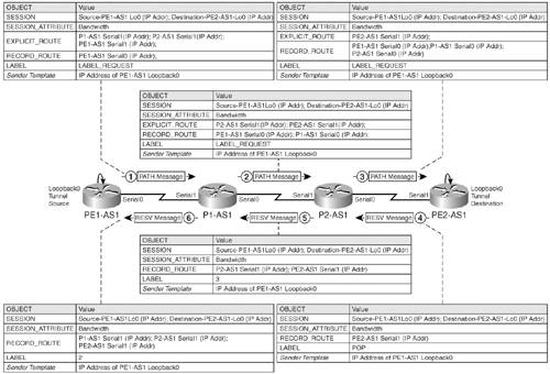
|
|
Step 3. |
The process is repeated at P2-AS1 in which references to its local interface in the EXPLICIT_ROUTE object are removed and appends the outgoing interface in the RECORD_ROUTE object. |
|
Step 4. |
After the RSVP PATH message is received by the tailend Router PE2-AS1, it triggers the creation of a RESERVATION message. The key concept to note is that the label allocation process begins at the tailend router upon generation of the RESERVATION message upstream. Therefore, when PE2-AS1 generates a RESERVATION message, the router assigns a POP label to the LSP tunnel (penultimate hop popping). The RESERVATION message now has the RECORD_ROUTE object pointing to the outgoing interface on the tailend router toward the headend router. Therefore, the RECORD_ROUTE object is reinitiated in the RESERVATION message. The values are depicted in Figure 9-6. |
|
Step 5. |
When this reservation message reaches P2-AS1, the RECORD_ROUTE is prepended with the outgoing interface and the local label mapping to the LSP is also generated and mapped in the LABEL object. An arbitrary value of 3 has been depicted for this LABEL value in Figure 9-6. |
|
Step 6. |
This process is again repeated on P1-AS1 and the RESERVATION message is then received by PE1-AS1. |
|
Step 7. |
When PE1-AS1 receives the RESERVATION message, the RECORD_ROUTE identifies the traffic engineered LSP associated to a specific bandwidth or resource requirement as defined in the SESSION object. The labels mapped to the LSP are thus used as in regular MPLS in which a local label is mapped to a next-hop label at each router that now maps to an RSVP-learned TE LSP versus a normal LSP. |
In the implementation of RSVP for MPLS TE, RSVP with extensions for TE requests as well as confirms the LSP, reserves resources as requested on all LSP path routers, and applies MPLS labels to form the MPLS LSP through the network. Note that the routers store a copy of the PATH request as the request is forwarded to the next-hop LSR. This information identifies the interface as reservation messages are received on the same LSR to an egress interface to the headend router. In the next section, you will be introduced to the constraint-based SPF calculation process and the need for a link-state protocol to enable MPLS TE dynamically in a service provider core.
MPLS Overview
- MPLS Overview
- Unicast IP Forwarding in Traditional IP Networks
- Overview of MPLS Forwarding
- MPLS Terminology
- MPLS Control and Data Plane Components
- MPLS Operation
- Special Outgoing Label Types
- Penultimate Hop Popping
- Frame-Mode MPLS
- Cell-Mode MPLS
Basic MPLS Configuration
- Basic MPLS Configuration
- Frame-Mode MPLS Configuration and Verification
- Cell-Mode MPLS over ATM Overview, Configuration, and Verification
- Command Reference
Basic MPLS VPN Overview and Configuration
- Basic MPLS VPN Overview and Configuration
- VPN Categories
- MPLS VPN Architecture and Terminology
- MPLS VPN Routing Model
- MPLS VPN Basic Configuration
- Outbound Route Filters
- Command Reference
PE-CE Routing Protocol-Static and RIP
- PE-CE Routing Protocol-Static and RIP
- Static PE-CE Routing Overview, Configuration, and Verification
- Static PE-CE Routing Command Reference
- RIPv2 PE-CE Routing Overview, Configuration, and Verification
- RIPv1 PE-CE Routing Configuration and Verification
- RIP PE-CE Routing Command Reference
PE-CE Routing Protocol-OSPF and EIGRP
- PE-CE Routing Protocol-OSPF and EIGRP
- OSPF PE-CE Routing Protocol Overview, Configuration and Verification
- EIGRP PE-CE Routing Protocol Overview, Configuration, and Verification
Implementing BGP in MPLS VPNs
- Implementing BGP in MPLS VPNs
- BGP PE-CE Routing Protocol Overview, Configuration, and Verification
- Implementing Route-Reflectors in MPLS VPN Networks
- Case Study-Hub and Spoke MPLS VPN Network Using BGP PE-CE Routing for Sites Using Unique AS Numbers
- Case Study-Hub and Spoke MPLS VPN Network with Sites Using Same AS Numbers
- Command Reference
Inter-Provider VPNs
- Inter-Provider VPNs
- Overview of Inter-Provider VPNs
- Option 1: Inter-Provider VPN Using Back-to-Back VRF Method
- Option 2: Inter-Provider VPNs Using ASBR-to-ASBR Approach
- Option 3: Multi-Hop MP-eBGP Between RR and eBGP Between ASBRs
- Option 4: Non-VPN Transit Provider
- Case Study-Inter-AS Implementing Route-Reflector and BGP Confederation in Provider Networks
- Case Study-Multi-Homed Inter-AS Provider Network
- Command Reference
Carrier Supporting Carriers
- Carrier Supporting Carriers
- Carrier Supporting Carriers Overview
- Deployment Scenarios with CSC Architecture
- CSC Architecture Benefits
- Command Reference
MPLS Traffic Engineering
- MPLS Traffic Engineering
- TE Basics
- MPLS TE Theory
- Constraint-Based Routing and Operation in MPLS TE
- Configuring MPLS TE
- Command Reference
Implementing VPNs with Layer 2 Tunneling Protocol Version 3
- Implementing VPNs with Layer 2 Tunneling Protocol Version 3
- L2TPv3 Overview
- Configuring L2TPv3 Tunnels for Layer 2 VPN
- Configuring L2TPv3 Static Tunnels
- Configuring L2TPv3 Dynamic Tunnels
- Implementing Layer 3 VPNs over L2TPv3 Tunnels
- Command Reference
Any Transport over MPLS (AToM)
- Any Transport over MPLS (AToM)
- Introduction to Layer 2 VPNs
- Implementing AToM for Like to Like Circuits
- L2 VPN-Any to Any Interworking
- Local Switching
- Command Reference
Virtual Private LAN Service (VPLS)
- Virtual Private LAN Service (VPLS)
- VPLS Overview
- VPLS Topology-Single PE or Direct Attachment
- Hierarchical VPLS-Distributed PE Architecture
- Command Reference
Implementing Quality of Service in MPLS Networks
- Implementing Quality of Service in MPLS Networks
- Introduction to QoS-Classification and Marking
- MPLS QoS Implementation
- MPLS QoS Operating Modes
- Modular QoS CLI: Configuration of QoS on Cisco Routers
- Configuration and Implementation of MPLS QoS in Uniform Mode and Short Pipe Mode Operation
- Implementing MPLS QoS for Layer 2 VPN Implementations
- Command Reference
MPLS Features and Case Studies
- MPLS Features and Case Studies
- Case Study 1: Implementing Multicast Support for MPLS VPNs
- Case Study 2: Implementing Multi-VRF CE, VRF Selection Using Source IP Address, VRF Selection Using Policy-Based Routing, NAT and HSRP Support in MPLS VPN, and Multicast VPN Support over Multi-VRF CE
- Case Study 3: Implementing Layer 2 VPNs over Inter-AS Topologies Using Layer 2 VPN Pseudo-Wire Switching
- Case Study 4: Implementing Layer 3 VPNs over Layer 2 VPN Topologies and Providing L2 VPN Redundancy
- Case Study 5: Implementing Dynamic Layer 3 VPNs Using mGRE Tunnels
- Case Study 6: Implementing Class-Based Tunnel Selection with MPLS Traffic Engineering
- Case Study 7: Implementing Hub and Spoke Topologies with OSPF
- Case Study 8: Implementing Hub and Spoke Topologies with EIGRP
- Case Study 9: Implementing VPLS Services with the GSR 12000 Series
- Case Study 10: BGP Site of Origin
- Command Reference
EAN: 2147483647
Pages: 130
