VPN Devices
Before describing the various VPN technologies and models, it is useful to first describe the various customer and provider network devices that are relevant to the discussion.
Devices in the customer network fall into one of two categories:
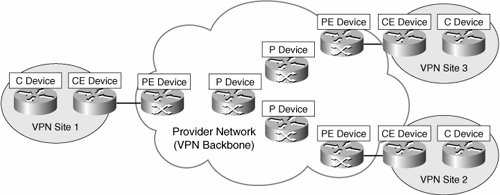
- Customer (C) devices C devices are simply devices such as routers and switches located within the customer network. These devices do not have direct connectivity to the service provider network. C devices are not aware of the VPN.
- Customer Edge (CE) devices CE devices, as the name suggests, are located at the edge of the customer network and connect to the provider network (via Provider Edge [PE] devices).
In CE-based VPNs, CE devices are aware of the VPN. In PE-based VPNs, CE devices are unaware of the VPN.
CE devices are either categorized as Customer Edge routers (CE-r), or Customer Edge switches (CE-s).
In a site-to-site VPN, devices in the service provider network also fall into one of two categories:
- Service Provider (P) devices P devices are devices such as routers and switches within the provider network that do not directly connect to customer networks. P devices are unaware of customer VPNs.
- Service Provider Edge (PE) devices PE devices connect directly to customer networks via CE devices. PE devices are aware of the VPN in PE-based VPNs, but are unaware of the VPN in CE-based VPNs.
There are three types of PE device:
- Provider Edge routers (PE-r)
- Provider Edge switches (PE-s)
- Provider Edge devices that are capable of both routing and switching (PE-rs)
Figure 1-1 illustrates customer and provider network devices.
Figure 1-1. Customer and Provider Network Devices
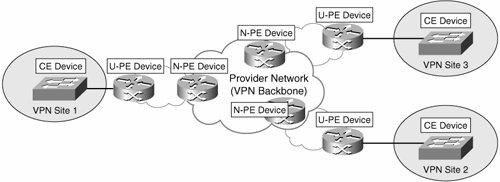
In Layer 2 VPNs, such as a Virtual Private LAN Service (VPLS), an additional level of hierarchy can be introduced into the network to improve scalability (VPLS then becomes Hierarchical VPLS [H-VPLS]). In this case, the functionality of the PE device is divided between a User-facing PE (U-PE) devices and Network-facing PE (N-PE) devices.
Note that alternative (and dated) equivalent terms for the U-PE and N-PE are PE-CLE and PE-POP, respectively. In addition, where a Layer 2 PE-U device is installed in a multitenant building, this may be referred to as an MTU-s. Figure 1-2 illustrates U-PE and N-PE devices.
Figure 1-2. User-Facing and Network-Facing PE Devices
Other device types used in VPNs include Network Access Servers (NAS) and VPN gateways/concentrators. A NAS is a device that interfaces between an access network (such as a Public Switched Telephone Network [PSTN]) and a packet-switched network (such as an IP backbone). In a remote access VPN, a NAS can serve as a tunnel endpoint.
Note that depending upon the remote access VPN protocol in use, the NAS may variously be called a Layer Two Forwarding (L2F) Protocol NAS, a Layer Two Tunneling Protocol (L2TP) Access Concentrator (LAC), or a Point-to-Point Tunneling Protocol (PPTP) Access Concentrator (PAC).
See Figure 1-5 for an illustration of the role performed by a NAS.
A VPN gateway/concentrator acts as the endpoint of a VPN tunnel, especially in a remote access VPN or CE-based site-to-site VPN. See Figure 1-5 later in the chapter for an illustration of the role performed by a VPN gateway/concentrator.
Depending on the remote access VPN protocol in use, the VPN gateway/concentrator may, for example, be called an L2F Home Gateway, an L2TP Network Server (LNS), or a PPTP Network Server (PNS).
VPN Technologies and Protocols
A number of technologies and protocols are used to enable site-to-site and remote access VPNs. These protocols and technologies are described in the sections that follow.
Technologies and Protocols Used to Enable Site-to-Site VPNs
In site-to-site VPNs (discussed later in this chapter), customer user data traffic is either tunneled between CE devices or between PE devices.
Note
Site-to-site VPNs are also occasionally referred to as LAN-to-LAN VPNs.
Protocols and technologies used to enable site-to-site VPNs include IP Security (IPsec), Generic Routing Encapsulation (GRE), the Layer Two Tunneling Protocol version 3 (L2TPv3), Draft Martini pseudowires (emulated circuits), IEEE 802.1Q tunneling (Q-in-Q), and MPLS Label Switched Paths (LSP). These protocols and technologies are described as follows:
- IPsec IPsec consists of a suite of protocols designed to protect IP traffic between security gateways or hosts as it transits an intervening network. IPsec tunnels are often used to build a site-to-site between CE devices (CE-based VPNs).
- GRE GRE can be used to construct tunnels and transport multiprotocol traffic between CE devices in a VPN. GRE has little or no inherent security, but GRE tunnels can be protected using IPsec.
- Draft Martini (Any Transport over MPLS [AToM]) Draft Martini transport allows point-to-point transport of protocols such as Frame Relay, ATM, Ethernet, Ethernet VLAN (802.1Q), High-Level Data Link Control (HDLC), and PPP traffic over MPLS.
- L2TPv3 L2TPv3 allows the point-to-point transport of protocols such as Frame Relay, ATM, Ethernet, Ethernet VLAN, HDLC, and PPP traffic over an IP or other backbone.
- IEEE 802.1Q tunneling (Q-in-Q) 802.1Q tunneling allows a service provider to tunnel tagged Ethernet (802.1Q) customer traffic over a shared backbone. Customer 802.1Q traffic is tunneled over the shared provider backbone by prepending another 802.1Q tag.
- MPLS LSPs An LSP is a path via Label Switch Routers (LSR) in an MPLS network. Packets are switched based on labels prepended to the packet. LSPs may be signaled using the Tag Distribution Protocol (TDP), the Label Distribution Protocol (LDP), or the Resource Reservation Protocol (RSVP).
Technologies and Protocols Used to Enable Remote Access VPNs
Protocols used to enable remote access VPNs (discussed later in this chapter) include the following:
- The Layer Two Forwarding (L2F) Protocol L2F is a Cisco proprietary protocol that is designed to allow the tunneling of PPP (or Serial Line Interface Protocol [SLIP]) frames between a NAS and a VPN gateway device located at a central site. Remote access users connect to the NAS, and the PPP frames from the remote access user are then tunneled over the intervening network to the VPN (home) gateway.
- The Point-to-Point Tunneling Protocol (PPTP) PPTP is a protocol that was developed by a consortium of vendors, including Microsoft, 3Com, and Ascend Communications. Like L2F, PPTP allows the tunneling of remote access client PPP frames between a NAS and a VPN gateway/concentrator. PPTP also allows a tunnel to be set up directly from a remote access client to a VPN gateway/concentrator.
PPP encapsulated packets carried over PPTP tunnels are often protected using Microsoft Point-to-Point Encryption (MPPE).
- The Layer 2 Tunneling Protocol versions 2 and 3 (L2TPv2/L2TPv3) L2TP is an Internet Engineering Task Force (IETF) standard and combines the best features of L2F and PPTP. In a remote access environment, L2TP allows either tunneling of remote access client PPP frames via a NAS to a VPN gateway/concentrator or tunneling of PPP frames directly from the remote access client to the VPN gateway/concentrator.
L2TP has limited intrinsic security, and so L2TP tunnels are often protected using IPsec.
- IPsec As well as enabling site-to-site VPNs, IPsec can also be used to securely tunnel data traffic between remote access or mobile users and a VPN gateway/concentrator.
- The Secure Sockets Layer (SSL) SSL is a security protocol that was originally developed by Netscape Communications (SSL versions 1, 2, and 3), and it provides secure remote access for mobile users or home users. Functionality may be limited (when compared with L2F, PPTP, L2TPv2, or IPsec) if clientless SSL remote access VPNs are deployed.
Note that Transport Layer Security (TLS), an IETF standard, is similar to SSLv3.
In spite of the limited functionality provided by clientless SSL VPNs, one advantage of this type of remote access VPN is that no special client software is required because SSL is included in pretty much every web browser. Therefore, if a remote user has a web browser, the user has SSL client software.
Because no special client software is required other than a web browser, SSL VPNs are sometimes referred to as web VPNs or clientless VPNs.
More functionality may be added to SSL VPNs by installing specific SSL VPN client software on remote access client devices.
Modeling and Characterizing VPNs
A plethora of methods are used to model and characterize VPNs. The purpose of this section is to introduce and explain each of these models and characterizations.
As you read this section, you may ask yourself how it is that we have ended up with so many terms to describe VPNs. The answer is a desire to accurately describe the characteristics of a VPN protocol or technology but also a simple lack of coordination among protocol designers and engineers (this is getting much better), and on top of that a certain amount of "help" from our marketing colleagues ("How can I differentiate our products?").
As you read this section, be sure to refer to Figure 1-3. Figure 1-3 clarifies the relationship of the VPN models to each other; it also describes the VPN (tunneling) protocols and technologies associated with the various models.
Figure 1-3. Virtual Private Networks
Note that in Figure 1-3, F: denotes a former name for a particular technology.
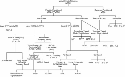
The bottom level of the hierarchy in Figure 1-3 describes protocols or mechanisms used to tunnel VPN traffic between CE or PE devices.
Service Provider and Customer Provisioned VPNs
VPNs can be either one of the following:
- Service provider provisioned VPNs that are configured and managed by a service provider or providers
- Customer provisioned VPNs that are configured and managed by the (service provider) customer itself
Note that the customer of the service provider may be either an enterprise or another service provider, in which case, the service provider that offers the VPN service is known as a carrier of carriers, and the service offered to the customer service provider is known as a carrier's carrier VPN service.
Additionally, a VPN service might be offered over the backbone networks of multiple cooperating autonomous systems and/or service providers. In this case, the VPN service is known as an inter-AS or interprovider VPN service.
Examples of provider provisioned VPNs are as follows:
- Virtual Private Wire Service (VPWS) VPNs
- Virtual Private LAN Service (VPLS) VPNs
- IP-Only Private LAN Service (IPLS) VPNs
- BGP/MPLS (RFC4364/2547bis) VPNs (BGP/MPLS VPNs are also known as MPLS Layer 3 VPNs.)
- Virtual Router (VR)-based VPNs
- IPsec VPNs
Examples of customer provisioned VPNs are as follows:
- GRE VPNs
- IPsec VPNs
Site-to-Site and Remote Access VPNs
VPNs, whether provider or customer provisioned, fall into one of two broad categories:
- Site to site
- Remote access
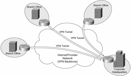
Site-to-site VPNs allow connectivity between an organization's (or organizations') geographically dispersed sites (such as a head office and branch offices).
Figure 1-4 illustrates a typical site-to-site VPN.
Figure 1-4. Typical Site-to-Site VPN
There are two types of site-to-site VPN:
- Intranet VPNs Allow connectivity between sites of a single organization
- Extranet VPNs Allow connectivity between organizations such as business partners or a business and its customers
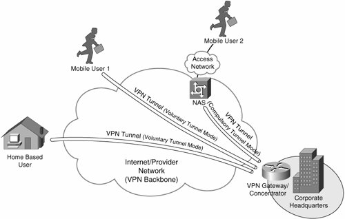
Remote access VPNs (also called access VPNs) allow mobile or home-based users to access an organization's resources remotely.
Figure 1-5 illustrates typical remote access VPNs.
Figure 1-5. Remote Access VPNs
Service Provider Provisioned Site-to-Site VPNs
Service provider provisioned site-to-site VPNs (PPVPN) fall into one of three categories: Layer 1 VPNs, Layer 2 VPNs, and Layer 3 VPNs. Layer 2 and Layer 3 site-to-site VPN types are described in the sections that follow.
Note
Layer 1 VPNs are used to transport Layer 1 services over an intervening shared network controlled and managed by Generalized Multiprotocol Label Switching (GMPLS).
At the time of this writing, the development of L1VPNs is in its relative infancy, and so L1VPNs are not discussed further in this book.
Layer 2 VPNs
Layer 2 site-to-site VPNs (L2VPN) can be provisioned between switches, hosts, and routers and allow data link layer connectivity between separate sites. Communication between customer switches, hosts, and routers is based on Layer 2 addressing, and PE devices perform forwarding of customer data traffic based on incoming link and Layer 2 header information (such as MAC address, Frame Relay Data Link Connection Identifier [DLCI], and so on).
There are two categories of provider provisioned L2VPN:
- Point-to-point (P2P) circuit-based VPNs P2P-based VPNs are also known as Virtual Private Wire Service (VPWS) VPNs and are constructed using, for example, Draft Martini (MPLS) or L2TPv3 pseudowires (emulated circuits).
It is worth noting that VPWS was formerly known as Virtual Leased Line Service (VLL service or VLLS).
- Multipoint-to-multipoint (M2M) VPNs M2M VPNs come in two varieties:
- Virtual Private LAN Service (VPLS) VPNs
- IP-Only LAN Service (IPLS) VPNs
Layer 3 VPNs
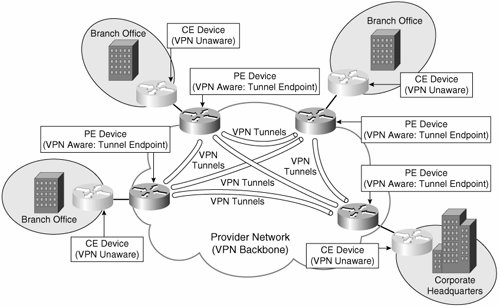
Layer 3 site-to-site VPNs (L3VPN) interconnect hosts and routers at separate customer sites. These customer hosts and routers communicate based on Layer 3 (network layer) addressing, and PE devices forward customer traffic based on incoming link, and on addresses contained in the (outer) IP header.
There are two overall types of L3VPN:
- PE-based VPNs In a PE-based L3VPN, PE devices participate in customer network routing and forward traffic based on customer network addressing. Customer traffic is (usually) forwarded between PE devices over VPN tunnels that may take the form of (MPLS) LSPs, IPsec tunnels, L2TPv3 tunnels, or GRE tunnels, for example. In this case, CE devices are not aware that they are participating in a VPN.
PE-based VPNs are also sometimes referred to as Network-based VPNs.
PE-based L3VPNs can be further classified as follows:
- RFC4364/2547bis styleIn this type of PE-based L3VPN, the PE devices maintain separate routing and forwarding tables for each VPN. Customer routes are advertised between PE devices using Multiprotocol Border Gateway Protocol (MP-BGP), and customer address space and routes are disambiguated using BGP attributes.
- Virtual Router (VR) basedIn this type of PE-based L3VPN, completely separate logical routers are maintained on the PE devices for each VPN. Each logical router maintains its own entirely separate routing protocol instances.
Figure 1-6 illustrates a typical PE-based VPN.
Figure 1-6. Typical PE-Based Site-to-Site VPN
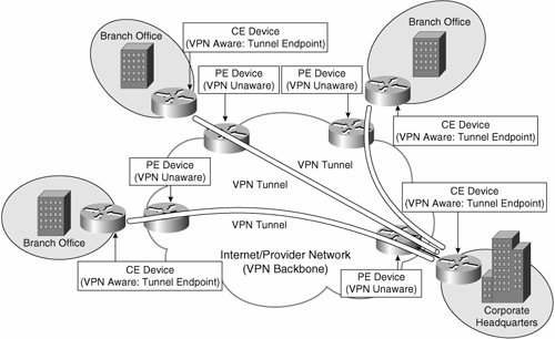
- CE-based VPNs In a CE-based L3VPN, PE devices do not participate in (and are unaware of) customer network routing and forward customer traffic based on globally unique addressing. In this case, tunnels are configured between CE devices using protocols such as GRE and IPsec.
CE-based VPNs are also sometimes referred to as CPE-based VPNs.
Figure 1-7 illustrates a typical CE-based site-to-site VPN.
Figure 1-7. Typical CE-Based Site-to-Site VPN
Customer Provisioned Site-to-Site VPNs
Customer provisioned site-to-site VPNs are configured on CE devices such as routers and firewalls. In this case, tunnels are configured between CE devices in the VPN, and customer data traffic is sent over these tunnels. Protocols used to encapsulate user data traffic as it is sent over the tunnels between VPN sites include GRE and IPsec.
Service Provider and Customer Provisioned Remote Access VPNs
Remote access VPNs can be configured in either compulsory tunnel mode or voluntary tunnel mode. These two modes of operation are described as follows:
- Compulsory tunnel mode Compulsory tunnel mode remote access VPNs are service provider provisioned. In this mode of operation, the remote access client connects to a NAS that then tunnels client data traffic to and from a VPN gateway. Compulsory tunnel mode remote access VPNs are provider provisioned. Examples of protocols used to provision compulsory tunnel mode remote access are L2F, PPTP, and L2TP.
In Figure 1-5, mobile user 2 is connected via a compulsory mode tunnel to the VPN gateway/concentrator.
Compulsory tunnel mode remote access VPNs are sometimes referred to as NAS-initiated remote access VPNs.
- Voluntary tunnel mode Voluntary tunnel mode remote access VPNs are either service provider or customer provisioned. In this mode of operation, data traffic is tunneled directly between the remote access client and a VPN gateway. Voluntary tunnel mode remote access VPNs can be either customer or provider provisioned.
In Figure 1-5, the home-based user and mobile user 1 are both connected to the VPN gateway/concentrator via voluntary mode tunnels.
Note that voluntary tunnel mode remote access VPNs are sometimes referred to as client-initiated remote access VPNs.
One type of remote access VPN is a Virtual Private Dialup Network (VPDN). This term can be used to describe remote access VPNs (L2F, PPTP, and L2TP) in which remote users connect over a PSTN or Integrated Services Digital Network (ISDN) to a dial NAS. User data traffic is then tunneled to a VPN gateway. With so many remote users now connecting over cable, Digital Subscriber Line (DSL), and other high-speed connections, rather than via dial connections, this term is slightly outdated.
Other Methods of Categorizing VPNs
Yes, there are yet more methods of categorizing VPNs! VPNs can be further categorized depending on whether they are connection oriented or connectionless, whether they are overlay or peer to peer, and whether they are secure or trusted.
Overlay and Peer-to-Peer VPNs
A VPN can be categorized as either an overlay or peer VPN depending on whether PE devices are aware of customer network addressing, and route customer traffic based on customer network address space.
Overlay and peer VPNs are summarized as follows:
- Overlay VPNs In an overlay network, a VC or tunnel connects CE devices. No routing information is exchanged with the service provider, and PE devices are unaware of customer network address space and do not route customer traffic based on customer network addressing.
Examples of overlay VPNs include those built using Frame Relay or ATM virtual circuits, as well as those built using GRE or IPsec tunnels.
- Peer VPNs In a peer VPN, PE devices are aware of customer network addressing and route customer data traffic according to customer network addressing. In peer VPNs, routes are exchanged between CE devices and PE devices.
Older types of peer VPN often involve PE devices partitioning customer data traffic by simply using access control lists (ACL). A more modern example of peer VPNs is BGP/MPLS (RFC4364/2547bis) VPNs.
Connection-Oriented and Connectionless VPNs
VPNs can be either connection oriented or connectionless depending on whether VCs or tunnels are provisioned to carry VPN traffic.
Connection-oriented and connectionless VPNs are described as follows:
- Connection-oriented VPNs In connection-oriented VPNs, VCs or tunnels are set up to carry VPN traffic.
Examples of connection-oriented VPNs are those provisioned using Frame Relay or ATM VCs, as well as those provisioned using L2TP or IPsec tunnels.
- Connectionless VPNs In connectionless VPNs, neither VCs nor tunnels are set up to carry VPN traffic.
PE-based VPNs that rely on the partitioning of customer data traffic by using ACLs configured on PE devices are connectionless VPNs.
Trusted and Secure VPNs
VPNs can be described as being either trusted or secure. Whether a VPN is trusted or secure depends on whether customer data traffic is authenticated and encrypted as it passes between VPN peers (sites in an site-to-site VPN, or a remote access client and a VPN gateway/concentrator in a remote access VPN).
Trusted and secure VPNs are described as follows:
- Trusted VPNs Provisioned by a service provider, and although customer traffic is not encrypted over the service provider backbone, customers trust the service provider to ensure that data traffic is kept secure in transit between the customer's sites.
Examples of trusted VPNs are Frame Relay, ATM, and BGP/MPLS (RFC4364/2547bis) VPNs.
- Secure VPNs Customer data traffic data is authenticated and encrypted over the service provider backbone or Internet between VPN peers.
Examples of secure VPNs are IPsec VPNs, SSL VPNs, PPTP VPNs secured with MPPE, and L2TP VPNs secured using IPsec.
And Finally. . .
And finally, here are two or three sundry VPN classifications:
- Transport/Application Layer VPNs SSL sits on top of TCP in the protocol stack, and SSL VPNs are therefore sometimes referred to as either Transport or Application Layer VPNs.
- Internet VPNs Designed to run over the public Internet.
- Multiservice VPNs Provide a framework for converged services, including voice, video, and data.
Part I: Understanding VPN Technology
What Is a Virtual Private Network?
- What Is a Virtual Private Network?
- VPN Devices
- Deploying Site-to-Site and Remote Access VPNs: A Comparison
- Summary
- Review Questions
Part II: Site-to-Site VPNs
Designing and Deploying L2TPv3-Based Layer 2 VPNs
- Designing and Deploying L2TPv3-Based Layer 2 VPNs
- Benefits and Drawbacks of L2TPv3-Based L2VPNs
- L2TPv3 Pseudowire Operation
- Configuring and Verifying L2TPv3 Pseudowires
- Summary
- Review Questions
Designing and Implementing AToM-Based Layer 2 VPNs
- Designing and Implementing AToM-Based Layer 2 VPNs
- Benefits and Drawbacks of AToM-Based L2VPNs
- AToM Pseudowire Operation
- Deploying AToM Pseudowires
- Implementing Advanced AToM Features
- Summary
- Review Questions
Designing MPLS Layer 3 Site-to-Site VPNs
- Designing MPLS Layer 3 Site-to-Site VPNs
- Advantages and Disadvantages of MPLS Layer 3 VPNs
- MPLS Layer 3 VPNs Overview
- A Detailed Examination of MPLS Layer 3 VPNs
- Deploying MPLS Layer 3 VPNs
- Summary
- Review Questions
Advanced MPLS Layer 3 VPN Deployment Considerations
- Advanced MPLS Layer 3 VPN Deployment Considerations
- The Carriers Carrier Architecture
- The Inter-Autonomous System/Interprovider MPLS VPN Architecture
- Supporting Multicast Transport in MPLS Layer 3 VPNs
- Implementing QoS for MPLS Layer 3 VPNs
- Supporting IPv6 Traffic Transport in MPLS Layer 3 VPNs Using 6VPE
- Summary
- Review Questions
Deploying Site-to-Site IPsec VPNs
- Deploying Site-to-Site IPsec VPNs
- Advantages and Disadvantages of IPsec Site-to-Site VPNs
- IPsec: A Security Architecture for IP
- Deploying IPsec VPNs: Fundamental Considerations
- Summary
- Review Questions
Scaling and Optimizing IPsec VPNs
- Scaling and Optimizing IPsec VPNs
- Scaling IPsec Virtual Private Networks
- Ensuring High Availability in an IPsec VPN
- Designing QoS for IPsec VPNs
- MTU and Fragmentation Considerations in an IPsec VPN
- Summary
- Review Questions
Part III: Remote Access VPNs
Designing and Implementing L2TPv2 and L2TPv3 Remote Access VPNs
- Designing and Implementing L2TPv2 and L2TPv3 Remote Access VPNs
- Benefits and Drawbacks of L2TP Remote Access VPNs
- Operation of L2TP Voluntary/Client-Initiated Tunnel Mode
- Implementing L2TP Voluntary/Client-Initiated Tunnel Mode Remote Access VPNs
- Designing and Implementing L2TP Compulsory/NAS-Initiated Tunnel Mode Remote Access VPNs
- Integrating L2TP Remote Access VPNs with MPLS VPNs
- Summary
- Review Questions
Designing and Deploying IPsec Remote Access and Teleworker VPNs
- Designing and Deploying IPsec Remote Access and Teleworker VPNs
- Comparing IPsec Remote Access VPNs with Other Types of Remote Access VPNs
- Understanding IKE in an IPsec Remote Access VPN Environment
- Deploying IPsec Remote Access VPNs Using Preshared Key and Digital Signature Authentication
- Summary
- Review Questions
Designing and Building SSL Remote Access VPNs (WebVPN)
- Designing and Building SSL Remote Access VPNs (WebVPN)
- Comparing SSL VPNs to Other Types of Remote Access VPNs
- Understanding the Operation of SSL Remote Access VPNs
- Using Clientless SSL Remote Access VPNs (WebVPN) on the Cisco VPN 3000 Concentrator
- Implementing Full Network Access Using the Cisco SSL VPN Client
- Strengthening SSL Remote Access VPNs Security by Implementing Cisco Secure Desktop
- Enabling SSL VPNs (WebVPN) on Cisco IOS Devices
- Deploying SSL VPNs (WebVPN) on the ASA 5500
- Summary
- Review Questions
Part IV: Appendixes
Designing and Building SSL Remote Access VPNs (WebVPN)
- Designing and Building SSL Remote Access VPNs (WebVPN)
- Appendix A. VPLS and IPLS Layer 2 VPNs
- Understanding VPLS
- Understanding IPLS
- Summary: Comparing VPLS and IPLS
Appendix B. Answers to Review Questions
EAN: 2147483647
Pages: 124
