Designing QoS for IPsec VPNs
Quality of service (QoS) describes a number of mechanisms that prioritize some traffic over other traffic. QoS is sometimes known as "managed unfairness."
As previously described, you can implement QoS in a network in two ways:
- Using the Differentiated Services (DiffServ) model
- Using the Integrated Services (IntServ) model
There are important considerations when using DiffServ and/or IntServ in an IPsec VPN, as described in the following two sections.
Using DiffServ in an IPsec VPN
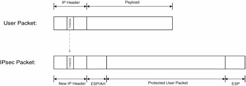
RFC2401 specifies that the contents of the type of service (ToS) or Differentiated Services (DS) field in the IP header of a protected user packet must be copied to the outer header of a tunnel mode IPsec packet. The ToS or DS field is maintained in the outer IP header of an IPsec transport mode packet.
Note
Copying of the ToS/DS field is supported in all Cisco IOS releases that support IPsec. Copying of the ToS/DS field is also supported in PIX software release 5.1 and later and VPN 3000 concentrator software release 3.5 and later.
Figure 7-54 illustrates the copying of the ToS/DS field from the protected user packet to the outer IP header of an IPsec tunnel mode packet.
Figure 7-54. Copying of the ToS/DS Field from the Protected User Packet to the Outer IP Header of an IPsec Tunnel Mode Packet
When deploying QoS in an IPsec VPN, it is important to consider that after a user packet has been encapsulated in IPsec (producing an IPsec packet), much if not all information that could be used to classify a packet is unavailable.
Information from the original user packet IP header that is maintained or copied to the outer IP header of an IPsec packet is as follows:
- Transport mode All information is maintained except the IP protocol number that is modified to reflect the (initial) security protocol (ESP/AH). Note that the IP protocol number indicates the protocol such as TCP, UDP, ESP, or AH that comes directly after the IP header.
- Tunnel mode The ToS/DS field is copied from the encapsulated user packet IP header.
See Figure 7-67 later in this chapter to see the IP header.
Figure 7-55 illustrates classification of IPsec packets on router in the path between IPsec VPN gateways.
Figure 7-55. Router Between the IPsec VPN Gateways Tries to Classify an IPsec Packet

In Figure 7-55, the IPsec VPN gateway encapsulates a user packet with IPsec, and when that packet arrives at the next-hop router, it is unable to classify the packet using user packet information because this information is hidden by IPsec.
So, if you want to classify packets based on user packet information such as IP protocol number, TCP port number, or UDP port number, you should classify and mark the ToS/DS field of the packet prior to IPsec encapsulation in normal operation.
In Figure 7-55, for example, if you want to classify and mark the packet based on user packet information such as IP protocol, TCP port number, or UDP port number, you must do it on the IPsec VPN gateway.
In any network (including an IPsec VPN), classification and marking of user packets should be performed as close the packets' source as possible. Some user applications and end devices such as IP phones may mark user packets by default.
In some customer-managed IPsec VPNs, it might be acceptable to trust the ToS/DS field marking performed by user applications and end devices. In many customer-managed and most if not all provider-managed IPsec VPNs, however, it is necessary to reclassify and re-mark user packets on an IPsec VPN gateway. IPsec VPN gateways, therefore, often function as a QoS trust boundary between the customer network and the service provider network.
After packets have been classified and marked, and if the IPsec VPN is provisioned over a private service provider network, intermediate devices between IPsec VPN gateways can schedule (queue) packets without having to reclassify those packets.
Figure 7-56 shows typical classification, marking, and scheduling of packets in an IPsec VPN provisioned over a private service provider backbone network.
Figure 7-56. Classification, Marking, and Scheduling of Packets in an IPsec VPN Provisioned over a Private Service Provider Network
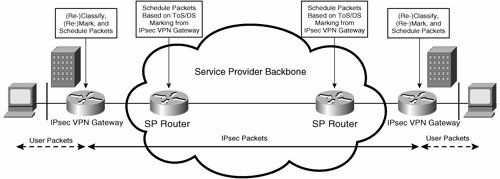
In Figure 7-56, the IPsec VPN gateways are responsible for classifying and marking packets, and the service provider routers then schedule IPsec packets based on the (ToS/DS) marking performed on the IPsec VPN gateways.
Note that IPsec VPN gateways and service provider routers shown in Figure 7-56 might also perform traffic shaping and policing, respectively.
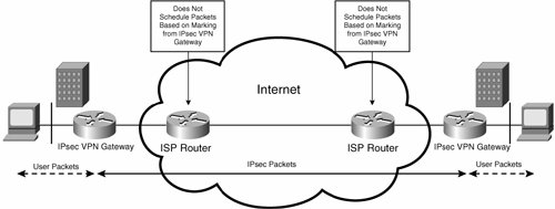
If the IPsec VPN is provisioned over the public Internet, intermediate devices between IPsec VPN gateways will not typically schedule packets based on marking done on IPsec VPN gateways.
Figure 7-57 shows typical scheduling of packets in an IPsec VPN provisioned over the public Internet. As Figure 7-57 shows, ISP routers do not schedule packets based on any marking performed on IPsec VPN gateways.
Although it is possible to configure traffic shaping on IPsec VPN gateways where the IPsec VPN is provisioned over the Internet, IPsec VPNs provisioned over the public Internet provide best-effort service, with no guarantees.
Figure 7-57. Scheduling of Packets in an IPsec VPN Provisioned over the Public Internet
Configuring QoS with the qos pre-classify Command
If you want to classify, mark, and schedule packets on IPsec VPN gateways, you must carefully configure the IPsec VPN gateways. Careful configuration of the IPsec VPN gateways is necessary because when packets are encapsulated in IPsec, the information that is available to help you classify packets is, as previously mentioned, limited.
Figure 7-58 illustrates information available to classify packets on IPsec VPN gateways.
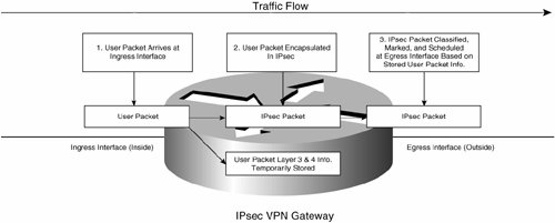
Figure 7-58. Information Available for the Classification of Packets on IPsec VPN Gateways
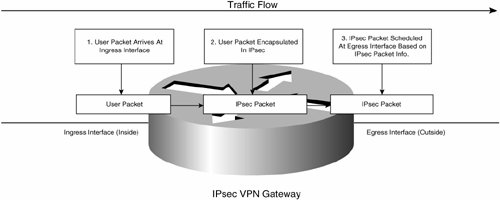
As you can see in Figure 7-58, if you want to classify and mark packets based on user packet layer information, such as TCP or UDP port, in normal operation you have to do it on the IPsec VPN gateway's ingress interface (prior to the user packets being encapsulated by IPsec).
In normal operation, classification on the egress interface of an IPsec VPN gateway can only be based on information in the outer header of IPsec packetsremember that IPsec encapsulated the user packet, and most user packet information is hidden.
In normal operation, therefore, classification of packets for queuing and scheduling mechanisms on the egress interface is based on fields in the outer IP header of IPsec packets.
Example 7-65 shows the configuration of a QoS policy in normal operation.
Example 7-65. QoS Policy in Normal Operation
London#show running-config Building configuration... Current configuration : 2546 bytes ! version 12.3 ! class-map match-all critical-data (line 1) match access-group 199 class-map match-any real-time-traffic (line 2) match ip rtp 16384 16383 match access-group 198 ! ! policy-map voice-data-policy (line 3) class critical-data set ip dscp 25 bandwidth percent 40 class real-time-traffic set ip dscp ef priority percent 30 class class-default set ip dscp default bandwidth percent 30 ! interface Serial1/0 ip address 192.168.1.1 255.255.255.0 max-reserved-bandwidth 100 service-policy output voice-data-policy (line 4) crypto map mjlnetmap ! access-list 198 permit tcp any any eq 1720 (line 5) access-list 199 permit tcp any any eq telnet (line 6) ! |
Highlighted lines 1, 2, 3, and 4 show the configuration of a sample Class-Based Weighted Fair Queuing (CBWFQ) policy called voice-data-policy and its application to egress (outside) interface serial 1/0 of an IPsec VPN gateway.
The CBWFQ policy defines three traffic classes:
- critical-data Matches traffic specified in access list 199 (see highlighted line 6)
- real-time-traffic Matches voice traffic (Real Time Transport Protocol [RTP] traffic on even ports in UDP port range 16384 and 32767) and call signaling traffic as specified in access list 198 (see highlighted line 5)
- class-default Matches all other IP traffic
Note
The specific QoS policy shown in Example 7-65 is used for illustrative purposes only and is not necessarily recommended for live deployments. QoS policy will vary according to the requirements of each particular IPsec VPN.
Traffic matching all three classes in the CBWFQ policy is sent across the IPsec VPN, and the show policy-map interface interface-name command is used to verify traffic matching the three traffic classes in the CBWFQ policy, as shown in Example 7-66.
Example 7-66. Verifying Traffic Matching the CBWFQ Policy
London#show policy-map interface serial 1/0 Serial1/0 Service-policy output: voice-data-policy Class-map: critical-data (match-all) 0 packets, 0 bytes 5 minute offered rate 0 bps, drop rate 0 bps Match: access-group 199 QoS Set dscp 25 Packets marked 0 (line 1) Queueing Output Queue: Conversation 265 Bandwidth 40 (%) Bandwidth 617 (kbps) Max Threshold 64 (packets) (pkts matched/bytes matched) 0/0 (depth/total drops/no-buffer drops) 0/0/0 Class-map: real-time-traffic (match-any) 0 packets, 0 bytes 5 minute offered rate 0 bps, drop rate 0 bps Match: ip rtp 16384 16383 0 packets, 0 bytes 5 minute rate 0 bps Match: access-group 198 0 packets, 0 bytes 5 minute rate 0 bps QoS Set dscp ef Packets marked 0 (line 2) Queueing Strict Priority Output Queue: Conversation 264 Bandwidth 30 (%) Bandwidth 463 (kbps) Burst 11575 (Bytes) (pkts matched/bytes matched) 0/0 (total drops/bytes drops) 0/0 Class-map: class-default (match-any) 1904 packets, 218399 bytes 5 minute offered rate 12000 bps, drop rate 0 bps Match: any QoS Set dscp default Packets marked 1866 (line 3) Queueing Output Queue: Conversation 266 Bandwidth 30 (%) Bandwidth 463 (kbps) Max Threshold 64 (packets) (pkts matched/bytes matched) 1892/219756 (depth/total drops/no-buffer drops) 0/0/0 London# |
In highlighted lines 1 and 2, you can see that there no packets have matched the critical-data and real-time-traffic classes, and in highlighted line 3 that 1866 packets have matched the class-default class.
Hmm? What is going on here? Traffic matching the critical-data and real-time-traffic classes is definitely being sent over the IPsec VPN, but it is not being matched by the CBWFQ policy.
The answer is that because the CBWFQ policy is applied to the egress interface, traffic that would otherwise match the critical-data and real-time-traffic classes is already encapsulated by IPsec by the time it reaches the IPsec VPN's egress interface, and so it does not in fact match the critical-data and real-time-traffic classes. Instead, all (IPsec) traffic matches the class-default class.
So, the problem is that when user packets are encapsulated in IPsec, most information (including TCP and UDP port numbers) is unavailable for matching.
From Cisco IOS Software Release 12.1(5)T or later on the 7200 platform, and from Cisco IOS Software Release 12.2(2)T on 2600 or 3600 platforms, however, it is possible to get around this problem of unavailable user packet information using the qos pre-classify command.
The qos pre-classify command allows an IPsec VPN gateway to temporarily store Layer 3 and 4 information from original user packets so that the corresponding IPsec-encapsulated packets can be classified, queued, and scheduled on the egress (outside) interface according to the original Layer 3 and 4 information.
Figure 7-59 illustrates the effect of the qos pre-classify command.
Figure 7-59. Effect of the qos pre-classify Command
In this example, a plain IPsec tunnel (without GRE) is being used, and so the qos pre-classify command is applied within the crypto map, as shown in Example 7-67. Note that only relevant configuration is shown.
Example 7-67. Verifying Traffic Matching the CBWFQ Policy
London#conf t Enter configuration commands, one per line. End with CNTL/Z. London(config)#crypto map mjlnetmap 10 ipsec-isakmp London(config-crypto-map)#qos pre-classify London(config-crypto-map)#end London# |
After the qos pre-classify command has been configured, traffic matches the critical-data and real-time-traffic classes within the CBWFQ policy, as shown in the output of the show policy-map interface command in Example 7-68.
Example 7-68. Verifying Traffic Matching the CBWFQ Policy
London#show policy-map interface serial 1/0 Serial1/0 Service-policy output: voice-data-policy Class-map: critical-data (match-all) 5534 packets, 863304 bytes 5 minute offered rate 13000 bps, drop rate 0 bps Match: access-group 199 QoS Set dscp 25 Packets marked 5534 (line 1) Queueing Output Queue: Conversation 265 Bandwidth 40 (%) Bandwidth 617 (kbps) Max Threshold 64 (packets) (pkts matched/bytes matched) 5534/863304 (depth/total drops/no-buffer drops) 0/0/0 Class-map: real-time-traffic (match-any) 5285 packets, 613060 bytes 5 minute offered rate 0 bps, drop rate 0 bps Match: ip rtp 16384 16383 0 packets, 0 bytes 5 minute rate 0 bps Match: access-group 198 5285 packets, 613060 bytes 5 minute rate 0 bps QoS Set dscp ef Packets marked 5285 (line 2) Queueing Strict Priority Output Queue: Conversation 264 Bandwidth 30 (%) Bandwidth 463 (kbps) Burst 11575 (Bytes) (pkts matched/bytes matched) 5285/613060 (total drops/bytes drops) 0/0 Class-map: class-default (match-any) 6431 packets, 737805 bytes 5 minute offered rate 0 bps, drop rate 0 bps Match: any QoS Set dscp default Packets marked 6271 Queueing Output Queue: Conversation 266 Bandwidth 30 (%) Bandwidth 463 (kbps) Max Threshold 64 (packets) (pkts matched/bytes matched) 6271/727304 (depth/total drops/no-buffer drops) 0/0/0 London# |
As you can see in highlighted lines 1 and 2, packets are now matching the critical-data and real-time-data classes and are marked and scheduled accordingly.
If you are using GRE tunnels to carry multiprotocol or multicast traffic, you must apply the qos pre-classify command within the crypto map and on the GRE tunnel interface, as shown in Example 7-69. Note that only relevant configuration is shown.
Example 7-69. Configuring the qos pre-classify Command with GRE/IPsec Tunnels
! crypto map mjlnetmap 10 ipsec-isakmp set peer 192.168.2.2 set transform-set mjlnettrans match address 101 qos pre-classify (line 1) ! interface Tunnel0 ip address 10.3.3.1 255.255.255.0 qos pre-classify (line 2) tunnel source 192.168.1.1 tunnel destination 192.168.2.2 ! |
In highlighted lines 1 and 2, the qos pre-classify command is configured under the crypto map and tunnel interface respectively.
If you are using mGRE tunnels with DMVPN, you only need to apply the qos pre-classify command on the mGRE tunnel interface, as shown in Example 7-70. Note that only relevant configuration is shown.
Example 7-70. Configuring the qos pre-classify Command with mGRE/IPsec Tunnels
! interface Tunnel0 ip address 10.3.3.1 255.255.255.0 ip nhrp authentication mjlnet ip nhrp map multicast dynamic ip nhrp network-id 1234 no ip split-horizon eigrp 100 qos pre-classify tunnel source 192.168.1.1 tunnel mode gre multipoint tunnel key 5678 tunnel protection ipsec profile mjlnetprofile ! |
The highlighted line shows where the qos re-classify command is configured under the mGRE tunnel interface.
Before finishing this section, it is worth noting that you cannot configure the qos pre-classify command in conjunction with legacy priority queuing (configured using the priority-list and priority-group command).
IPsec Anti-Replay Considerations with QoS
One feature of IPsec that you can implement in conjunction with both AH and ESP is protection against duplicate IPsec packets sent by an attacker. Protection against duplicate packets is known as replay protection and when implemented causes a receiving IPsec VPN gateway to just drop duplicate IPsec packets. Replay protection can have implications in an IPsec VPN where packet scheduling based on ToS or DS field values (such as IP Precedence or Differentiated Services Code Point [DSCP]) is implemented in the backbone network between IPsec VPN gateways.
IPsec uses unique packet sequence numbers to protect against replay attacks. Each packet associated with a particular SA is sent with a unique sequence number, and the sequence number increases by one every time an IPsec VPN gateway sends a packet for that IPsec SA.
Figure 7-60 illustrates IPsec packet sequence numbers.
Figure 7-60. IPsec Packet Sequence Numbers
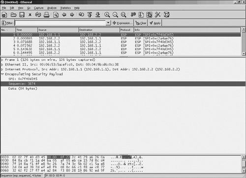
In the first highlighted line in Figure 7-60, you can see an ESP packet sent from IPsec VPN gateway 192.168.1.1 to IPsec VPN gateway 192.168.2.2. Notice the SPI of 0x7f40d345, which (together with the security protocol [ESP] and destination IP address) uniquely identifies the IPsec SA.
In the second highlighted line in Figure 7-60, you can see that the sequence number associated with this ESP packet is 3874.
If replay protection is implemented on a packet receiving IPsec VPN gateway, it maintains a sliding relay window. This replay window dictates whether the receiving IPsec VPN gateway will accept or discard IPsec packets that it receives.
Figure 7-61 illustrates the IPsec Replay Window. Note that a 10-packet replay window is used for illustrative purposes only.
Figure 7-61. IPsec Replay Window
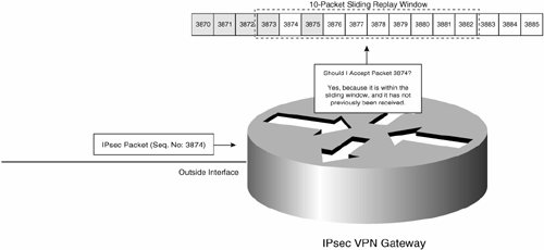
In Figure 7-61, the IPsec VPN gateway is implementing a 10-packet replay window. The gateway receives an IPsec packet with sequence number 3874, and because it is within the sliding window (from sequence number 3873 to 3882) and the gateway has not already received a packet with sequence number 3874, the gateway accepts the packet. Sequence numbers of packets that the gateway has already received are shaded gray in Figure 7-61.
In Figure 7-61, if the gateway were to receive an IPsec packet with sequence number of 3872, it would drop it because it would not be within the replay window. If the gateway were to receive an IPsec packet with sequence number of 3875, it would drop it because a packet with that sequence number has already been received.
If an IPsec VPN gateway receives a packet whose sequence number is to the right of the current window (has a sequence number which is greater than the largest current sequence number encompassed by the replay window), after the gateway has authenticated that packet, it shifts the replay window to the right to encompass the newly received packet.
Note
Although Figure 7-61 shows a 10-packet replay window, an IPsec replay window must be at least 32 packets, and preferably 64 packets.
Cisco IOS routers implement a 64-packet replay window, and Cisco PIX firewalls implement a 32-packet replay window.
Replay protection works well when IPsec packets are received in roughly the same order as they are sent by the transmitting IPsec VPN gateway. If IPsec packets become re-ordered in the backbone network between IPsec VPN gateways, this can cause the receiving IPsec VPN gateway to drop some IPsec packets, as illustrated in Figure 7-62.
Figure 7-62. Re-Ordering Causes IPsec Packet Drops
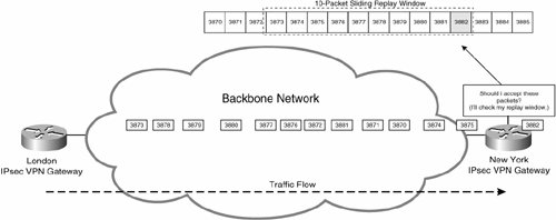
In Figure 7-62, the London IPsec VPN gateway sends 13 IPsec packets (with sequence numbers 3870 to 3882) in (correct) sequence to the New York gateway. Unfortunately, the IPsec packets become re-ordered in the backbone network, and the first packet that the New York gateway receives is IPsec packet with sequence number 3882.
When it receives packet 3882, the New York gateway shifts the (10-packet) replay window to the right to encompass packet 3882.
The New York gateway now receives the other 12 packets, but drops packets 3870, 3871, and 3872 because they do not fall within the (10-packet) replay window.
Although the extreme packet re-ordering shown in Figure 7-62 is unlikely, it is easy to see how packet re-ordering could result in some IPsec packets being dropped.
The big question is, how can packet re-ordering occur? One common cause of packet re-ordering is QoS packet scheduling in the backbone network between IPsec VPN gateways. If QoS is implemented in the backbone, some traffic will be prioritized over other traffic, and this inevitably leads to packet re-ordering.
The good news is that although packet re-ordering can occur when QoS is implemented in a backbone network, it is likely that the only packets dropped will be low-priority packets. This is because high-priority packets will travel faster over the backbone network; low-priority packets will travel more slowly. Some low-priority packets might, therefore, be outside (to the left of) the replay window when they are received on an IPsec VPN gateway.
If you do find that packets loss due to QoS scheduling in the backbone network is a problem, it is possible to overcome this by ensuring that separate IPsec SAs (and therefore separate replay windows) are negotiated for different traffic types. If you configure separate lines (traffic selectors) for different traffic types in your crypto access list, separate IPsec SAs are negotiated between IPsec VPN gateways for these traffic types. It would be possible, for example, to specify one line in your crypto access list to match all UDP traffic, and another line to match all TCP traffic, and each of these lines would be negotiated as a separate IPsec SA.
Note that IKEv1 does not allow the configuration of identical traffic selectors (defined in separate lines in crypto access lists) for IPsec SAs associated with separate quality of service. For example, in IKEv1 you cannot specify two identical traffic selectors for source IP address 10.1.1.0/24 and destination IP address 10.2.2.0/24, with one of the traffic selectors associated with an IPsec SA for DSCP 46 (Expedited Forwarding [EF]) and the other associated with an IPsec SA for DSCP 25.
IKEv2, on the other hand, specifies that identical traffic selectors may be used for separate IPsec SAs, each of which can be used, for example, for a separate QoS.
As a final note on packet re-ordering and replay protection, it is worth stating that replay protection is mandatory for the IPsec VPN gateways when sending IPsec packets (sequence numbers must be included in the packets), but that replay protection is not mandatory for the IPsec VPN gateways receiving IPsec packets (it is not mandatory for a receiver to implement a replay window).
Cisco routers implement a replay window for IPsec SAs except for ESP when authentication is not specified.
Tip
Beginning with Cisco IOS Software Release 12.3(14)T, it is possible to change the replay window size or even disable it using the crypto ipsec security-association replay window-size and crypto ipsec security-association replay disable global configuration mode commands (which affect all SAs), or the set security-association replay window-size and set security-association replay disable commands within a crypto map (which affect only those SAs associated with that crypto map).
Think carefully before changing the replay window size (the default is there for a good reason), and think especially carefully before disabling it.
Use the show crypto ipsec sa command to verify replay protection as shown in Examples 7-71 (IPsec SAs with authentication) and 7-72 (IPsec ESP SAs without authentication).
Example 7-71. Verifying Replay Protection for IPsec SAs (with Authentication)
London#show crypto ipsec sa
interface: Serial1/0
 Crypto map tag: mjlnetmap, local addr. 192.168.1.1
 protected vrf:
 local ident (addr/mask/prot/port): (10.1.1.0/255.255.255.0/0/0)
 remote ident (addr/mask/prot/port): (10.2.2.0/255.255.255.0/0/0)
 current_peer: 192.168.2.2:500
 PERMIT, flags={origin_is_acl,}
 #pkts encaps: 485, #pkts encrypt: 485, #pkts digest: 485
 #pkts decaps: 484, #pkts decrypt: 484, #pkts verify: 484
 #pkts compressed: 0, #pkts decompressed: 0
 #pkts not compressed: 0, #pkts compr. failed: 0
 #pkts not decompressed: 0, #pkts decompress failed: 0
 #send errors 6, #recv errors 0
 local crypto endpt.: 192.168.1.1, remote crypto endpt.: 192.168.2.2
 path mtu 1500, media mtu 1500
 current outbound spi: E5C7FCD
 inbound esp sas: (line 1)
 spi: 0x6BAC2CF5(1806445813)
 transform: esp-des esp-md5-hmac ,
 in use settings ={Tunnel, }
 slot: 0, conn id: 2000, flow_id: 1, crypto map: mjlnetmap
 crypto engine type: Software, engine_id: 1
 sa timing: remaining key lifetime (k/sec): (4493187/2247)
 ike_cookies: A0585410 105DCC1E 90A62179 A82ADF45
 IV size: 8 bytes
 replay detection support: Y
 spi: 0x8690C4AD(2257634477)
 transform: esp-des esp-md5-hmac ,
 in use settings ={Tunnel, }
 slot: 0, conn id: 2002, flow_id: 3, crypto map: mjlnetmap
 crypto engine type: Software, engine_id: 1
 sa timing: remaining key lifetime (k/sec): (4406361/2245)
 ike_cookies: A0585410 105DCC1E 90A62179 A82ADF45
 IV size: 8 bytes
 replay detection support: Y (line 2)
 inbound ah sas:
 inbound pcp sas:
 outbound esp sas: (line 3)
 spi: 0x74C8114A(1959268682)
 transform: esp-des esp-md5-hmac ,
 in use settings ={Tunnel, }
 slot: 0, conn id: 2001, flow_id: 2, crypto map: mjlnetmap
 crypto engine type: Software, engine_id: 1
 sa timing: remaining key lifetime (k/sec): (4493187/2245)
 ike_cookies: A0585410 105DCC1E 90A62179 A82ADF45
 IV size: 8 bytes
 replay detection support: Y
 spi: 0xE5C7FCD(240943053)
 transform: esp-des esp-md5-hmac ,
 in use settings ={Tunnel, }
 slot: 0, conn id: 2003, flow_id: 4, crypto map: mjlnetmap
 crypto engine type: Software, engine_id: 1
 sa timing: remaining key lifetime (k/sec): (4406360/2244)
 ike_cookies: A0585410 105DCC1E 90A62179 A82ADF45
 IV size: 8 bytes
 replay detection support: Y (line 4)
 outbound ah sas:
 outbound pcp sas:
London#
|
In highlighted lines 1 to 4, you can see that replay protection (shown as replay detection support) is supported (replay detection support: Y) for both inbound and outbound IPsec SAs (when receiving and sending IPsec packets) when the IPsec SAs specify authentication.
Example 7-72. Verifying Replay Protection IPsec ESP Without Authentication
London#show crypto ipsec sa
interface: Serial1/0
 Crypto map tag: mjlnetmap, local addr. 192.168.1.1
 protected vrf:
 local ident (addr/mask/prot/port): (10.1.1.0/255.255.255.0/0/0)
 remote ident (addr/mask/prot/port): (10.2.2.0/255.255.255.0/0/0)
 current_peer: 192.168.2.2:500
 PERMIT, flags={origin_is_acl,}

 #pkts encaps: 42, #pkts encrypt: 42, #pkts digest 0
 #pkts decaps: 26, #pkts decrypt: 26, #pkts verify 0
 #pkts compressed: 0, #pkts decompressed: 0
 #pkts not compressed: 0, #pkts compr. failed: 0
 #pkts not decompressed: 0, #pkts decompress failed: 0
 #send errors 1, #recv errors 0
 local crypto endpt.: 192.168.1.1, remote crypto endpt.: 192.168.2.2
 path mtu 1500, media mtu 1500
 current outbound spi: 7D0
 inbound esp sas: (line 1)
 spi: 0x3E8(1000)
 transform: esp-des ,
 in use settings ={Tunnel, }
 slot: 0, conn id: 2001, flow_id: 1, crypto map: mjlnetmap
 no sa timing
 IV size: 8 bytes
 replay detection support: N (line 2)
 inbound ah sas:
 inbound pcp sas:
 outbound esp sas: (line 3)
 spi: 0x7D0(2000)
 transform: esp-des ,
 in use settings ={Tunnel, }
 slot: 0, conn id: 2000, flow_id: 2, crypto map: mjlnetmap
 no sa timing
 IV size: 8 bytes
 replay detection support: N (line 4)
 outbound ah sas:
 outbound pcp sas:
London#
|
Highlighted lines 1 to 4 show that replay protection is not supported (replay detection support: N) for both inbound and outbound IPsec ESP SAs when authentication is not specified.
Other Considerations When Provisioning QoS for an IPsec VPN
There are a number of other considerations to take into account when provisioning QoS for an IPsec VPN. These considerations are as follows:
- RSVP does not work between IPsec VPN gateways because IPsec hides information about user traffic flows (such as Layer 4 information).
- The compressed RTP (cRTP) does not work with IPsec. In normal operation, cRTP compresses the IP, UDP, and RTP headers such that a G.729 packet is reduced from a total size of 60 bytes to 23 bytes. Unfortunately, the UDP and RTP headers (plus the IP header in IPsec tunnel mode) are hidden by IPsec, and so are unavailable for compression.
- Prior to Cisco IOS Software Release 12.2(13)T, IPsec supported a single first-in, first-out (FIFO) queue. This single crypto queue can impact delay-sensitive traffic when the crypto engine is congested because voice packets can get stuck behind large data packets in the FIFO queue.
Cisco IOS Software Release 12.2(13)T introduced a Low Latency Queue (LLQ) for IPsec. This LLQ ensures that high-priority traffic such as voice is guaranteed bandwidth and is encrypted before data traffic.
Figure 7-63 illustrates the single FIFO crypto queue prior to Cisco IOS Software Release 12.2(13)T, and the dual LLQ and FIFO queues in Cisco IOS Software Release 12.2(13)T and later.
Figure 7-63. Crypto Engine FIFO and LLQ Queues

Part I: Understanding VPN Technology
What Is a Virtual Private Network?
- What Is a Virtual Private Network?
- VPN Devices
- Deploying Site-to-Site and Remote Access VPNs: A Comparison
- Summary
- Review Questions
Part II: Site-to-Site VPNs
Designing and Deploying L2TPv3-Based Layer 2 VPNs
- Designing and Deploying L2TPv3-Based Layer 2 VPNs
- Benefits and Drawbacks of L2TPv3-Based L2VPNs
- L2TPv3 Pseudowire Operation
- Configuring and Verifying L2TPv3 Pseudowires
- Summary
- Review Questions
Designing and Implementing AToM-Based Layer 2 VPNs
- Designing and Implementing AToM-Based Layer 2 VPNs
- Benefits and Drawbacks of AToM-Based L2VPNs
- AToM Pseudowire Operation
- Deploying AToM Pseudowires
- Implementing Advanced AToM Features
- Summary
- Review Questions
Designing MPLS Layer 3 Site-to-Site VPNs
- Designing MPLS Layer 3 Site-to-Site VPNs
- Advantages and Disadvantages of MPLS Layer 3 VPNs
- MPLS Layer 3 VPNs Overview
- A Detailed Examination of MPLS Layer 3 VPNs
- Deploying MPLS Layer 3 VPNs
- Summary
- Review Questions
Advanced MPLS Layer 3 VPN Deployment Considerations
- Advanced MPLS Layer 3 VPN Deployment Considerations
- The Carriers Carrier Architecture
- The Inter-Autonomous System/Interprovider MPLS VPN Architecture
- Supporting Multicast Transport in MPLS Layer 3 VPNs
- Implementing QoS for MPLS Layer 3 VPNs
- Supporting IPv6 Traffic Transport in MPLS Layer 3 VPNs Using 6VPE
- Summary
- Review Questions
Deploying Site-to-Site IPsec VPNs
- Deploying Site-to-Site IPsec VPNs
- Advantages and Disadvantages of IPsec Site-to-Site VPNs
- IPsec: A Security Architecture for IP
- Deploying IPsec VPNs: Fundamental Considerations
- Summary
- Review Questions
Scaling and Optimizing IPsec VPNs
- Scaling and Optimizing IPsec VPNs
- Scaling IPsec Virtual Private Networks
- Ensuring High Availability in an IPsec VPN
- Designing QoS for IPsec VPNs
- MTU and Fragmentation Considerations in an IPsec VPN
- Summary
- Review Questions
Part III: Remote Access VPNs
Designing and Implementing L2TPv2 and L2TPv3 Remote Access VPNs
- Designing and Implementing L2TPv2 and L2TPv3 Remote Access VPNs
- Benefits and Drawbacks of L2TP Remote Access VPNs
- Operation of L2TP Voluntary/Client-Initiated Tunnel Mode
- Implementing L2TP Voluntary/Client-Initiated Tunnel Mode Remote Access VPNs
- Designing and Implementing L2TP Compulsory/NAS-Initiated Tunnel Mode Remote Access VPNs
- Integrating L2TP Remote Access VPNs with MPLS VPNs
- Summary
- Review Questions
Designing and Deploying IPsec Remote Access and Teleworker VPNs
- Designing and Deploying IPsec Remote Access and Teleworker VPNs
- Comparing IPsec Remote Access VPNs with Other Types of Remote Access VPNs
- Understanding IKE in an IPsec Remote Access VPN Environment
- Deploying IPsec Remote Access VPNs Using Preshared Key and Digital Signature Authentication
- Summary
- Review Questions
Designing and Building SSL Remote Access VPNs (WebVPN)
- Designing and Building SSL Remote Access VPNs (WebVPN)
- Comparing SSL VPNs to Other Types of Remote Access VPNs
- Understanding the Operation of SSL Remote Access VPNs
- Using Clientless SSL Remote Access VPNs (WebVPN) on the Cisco VPN 3000 Concentrator
- Implementing Full Network Access Using the Cisco SSL VPN Client
- Strengthening SSL Remote Access VPNs Security by Implementing Cisco Secure Desktop
- Enabling SSL VPNs (WebVPN) on Cisco IOS Devices
- Deploying SSL VPNs (WebVPN) on the ASA 5500
- Summary
- Review Questions
Part IV: Appendixes
Designing and Building SSL Remote Access VPNs (WebVPN)
- Designing and Building SSL Remote Access VPNs (WebVPN)
- Appendix A. VPLS and IPLS Layer 2 VPNs
- Understanding VPLS
- Understanding IPLS
- Summary: Comparing VPLS and IPLS
Appendix B. Answers to Review Questions
EAN: 2147483647
Pages: 124
