Ensuring High Availability in an IPsec VPN
When designing an IPsec VPN, one of the most important considerations is high availability, particularly in a hub-and-spoke topology. Ensuring high availability in an IPsec VPN means that resources are constantly available from spoke sites, even in the event of the failure of a single gateway at a hub site.
Figure 7-5 on page 533 illustrates the importance of high availability. The crucial thing to notice about the hub-and-spoke topology shown is that the hub site gateway is a single point of failure. That is, if the hub site gateway fails, spoke-to-hub site connectivity fails, as well as any site-to-site connectivity via the hub site. It is worth pointing out that even if you are using DMVPN, and spoke-to-spoke traffic is transported directly between spoke sites, the hub site gateway remains a single point of failure for spoke-to-spoke traffic because it functions as the NHS for the DMVPN (if the NHS goes down, the spoke sites will no longer be able to dynamically build tunnels between themselves).
There are several approaches to ensuring high availability in an IPsec VPN, the two most popular of which are as follows:
- Configuring high availability with HSRP
- Configuring high availability with GRE
These two approaches are described in the sections that follow.
High Availability with HSRP
One way of provisioning high availability at a hub site is by configuring a Hot Standby Routing Protocol (HSRP) group between redundant IPsec gateways. HSRP allows a group of routers to share virtual IP and MAC addresses. Traffic from end hosts or other network devices can then be forwarded to the virtual IP (and MAC) address, and as long as one of the routers in the HSRP group is in an up state, traffic continues to be forwarded.
When HSRP is used to provide IPsec high availability, remote IPsec gateways build IPsec tunnels to the HSRP virtual IP address rather than an IP address that corresponds to a single head-end (hub site) IPsec gateway. As long as one of the head-end IPsec gateways is in an up state, traffic continues to be forwarded to and from remote IPsec gateways.
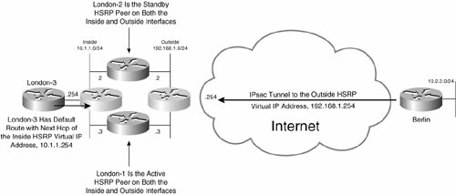
Figure 7-33 illustrates IPsec high availability with HSRP.
Figure 7-33. IPsec High Availability with HSRP
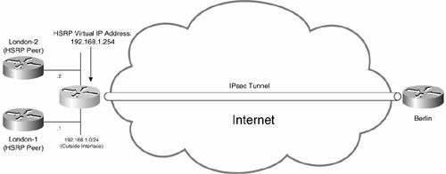
In Figure 7-33, gateways London-1 and London-2 constitute an HSRP group (on their outside interfaces) with a virtual IP address of 192.168.1.254. The remote Berlin IPsec gateway builds an IPsec tunnel to the HSRP virtual address rather than the individual IP addresses assigned to London-1 and London-2 (192.168.1.1 and 192.168.1.2, respectively). In this case, the active HSRP peer in the group is actually the endpoint of the IPsec tunnel. In the event that the active HSRP router (gateway) fails, the standby router takes over as the IPsec tunnel endpoint.
Okay, so the tunnel endpoint fails over to the HSRP standby router in the event of a failure of the active HSRP router. But, how exactly does this process occur? Does the tunnel failover without any loss of user data traffic, or will there be some kind of service interruption?
The answer to both of these questions depends on whether the routers in the HSRP group are configured for stateless or stateful IPsec high availability with HSRP.
Stateless IPsec High Availability
If head-end gateways London-1 and London-2 (see Figure 7-33) are configured for stateless IPsec high availability, no IPsec state information is replicated from the active HSRP peer to the standby HSRP peer. This means that if the existing active HSRP router London-1 (which maintains the IPsec SAs in its SADB) fails, remote IPsec gateway Berlin detects the failure via IKE (ISAKMP) keepalives and re-initiates IKE negotiation with the new active HSRP peer, London-2.
The renegotiation of SAs does mean that some user traffic is dropped. The failover time and associated amount of user traffic dropped depends, to a great extent, on the HSRP holdtime (the amount of time before the standby HSRP peer becomes active) and the IKE keepalive interval.
The IKE keepalive interval is specified using the crypto isakmp keepalive seconds [periodic] command. This command enables a mechanism that sends IKE keepalive messages at the time interval specified.
Figure 7-34 illustrates stateless IPsec high availability failover.
Figure 7-34. Stateless IPsec High Availability Failover
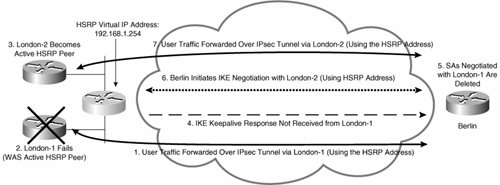
In Figure 7-34, the following events occur:
|
1. |
User traffic is forwarded over an IPsec tunnel via London-1. London-1 is the active HSRP active, and the HSRP virtual IP address (192.168.1.254) is the tunnel endpoint address. |
|
2. |
London-1 fails. |
|
3. |
London-2 detects the failure of London-1 and becomes the active HSRP peer. |
|
4. |
London-1 fails to respond to IKE keepalives from Berlin. |
|
5. |
Berlin deletes SAs negotiated with London-1. |
|
6. |
When it needs to send more user traffic to the London site, Berlin initiates IKE negotiation with London-2 (via the HSRP virtual IP address, 192.168.1.254). |
|
7. |
When IKE negotiation is complete, Berlin forwards user traffic over the new IPsec tunnel to London-2. |
That is the theory.
Stateless IPsec high availability can be configured in two ways:
- Stateless IPsec high availability with reverse route injection (RRI)
- Stateless IPsec high availability with HSRP on the inside interface
These two methods of configuration are discussed in the following sections.
Stateless IPsec High Availability with RRI
When stateless IPsec high availability is using with RRI, a static route to the remote network is injected into the routing table on the active HSRP peer. This static route is then (optionally) redistributed into a routing protocol such as EIGRP and advertised to other routers on the inside interface.
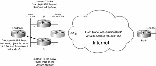
Figure 7-35 illustrates stateless IPsec high availability with RRI.
Figure 7-35. Stateless IPsec High Availability with RRI
Example 7-29 shows the configuration of Berlin.
Example 7-29. Configuration of Berlin for Stateless IPsec High Availability
Berlin#show running-config Building configuration... ! hostname Berlin ! ! crypto isakmp policy 10 hash md5 authentication pre-share crypto isakmp key cisco address 192.168.1.254 (line 1) crypto isakmp keepalive 10 (line 2) ! crypto ipsec transform-set mjlnettransform esp-des esp-md5-hmac ! crypto map mjlnetmap 10 ipsec-isakmp set peer 192.168.1.254 (line 3) set transform-set mjlnettransform match address 101 ! ! ! Outside interface ! interface FastEthernet0/0 ip address 192.168.2.2 255.255.255.0 crypto map mjlnetmap ! ! ! Inside interface ! interface FastEthernet1/0 ip address 10.2.2.1 255.255.255.0 ! ip route 0.0.0.0 0.0.0.0 192.168.2.1 ! access-list 101 permit ip 10.2.2.0 0.0.0.255 10.1.1.0 0.0.0.255 ! ! |
The first thing to notice about the configuration of Berlin is that there is little out of the ordinary. But, take a look at highlighted lines 1 and 3the peer IP address specified is the HSRP virtual IP address (see Figure 7-35). Also notice line 2the crypto isakmp keepalive seconds command configures Berlin to send IKE (ISAKMP) keepalives (every 10 seconds in this case).
Example 7-30 shows the configuration of London-1.
Example 7-30. Configuration of London-1 for Stateless IPsec High Availability with RRI
London-1#show running-config Building configuration... ! hostname London-1 ! crypto isakmp policy 10 authentication pre-share crypto isakmp key cisco address 192.168.2.2 crypto isakmp keepalive 10 (line 1) ! crypto ipsec transform-set mjlnettransform esp-des esp-sha-hmac ! crypto map mjlnetmap 10 ipsec-isakmp set peer 192.168.2.2 set transform-set mjlnettransform match address 101 reverse-route (line 2) ! ! ! Inside interface ! interface FastEthernet0/0 ip address 10.1.1.1 255.255.255.0 ! ! ! Outside interface ! interface FastEthernet3/0 ip address 192.168.1.1 255.255.255.0 standby 20 ip 192.168.1.254 (line 3) standby 20 priority 120 (line 4) standby 20 preempt (line 5) standby 20 name ipsecfailover2 (line 6) standby 20 track FastEthernet0/0 50 (line 7) crypto map mjlnetmap redundancy ipsecfailover2 (line 8) ! router eigrp 100 redistribute static (line 9) network 10.1.1.0 0.0.0.255 no auto-summary ! access-list 101 permit ip 10.1.1.0 0.0.0.255 10.2.2.0 0.0.0.255 (line 10) ! |
Highlighted line 1 shows the crypto isakmp keepalive seconds command. This command configures London-1 to send an IKE keepalive message every 10 seconds.
In line 2, the reverse-route command is configured within crypto map mjlnetmap. This command enables RRI, and when used with a static crypto map injects a static route or routes derived from the destination address(es) specified in the crypto access list. In this example, a static route to prefix 10.2.2.0/24 (specified as the destination address in the crypto access list shown in highlighted line 10) is injected into the routing table when London-1 is the active HSRP peer. This static route is then redistributed into EIGRP (the dynamic routing protocol used at the London site in this example), as shown in highlighted line 9.
In lines 3 to 5, HSRP group 20 with virtual IP address 192.168.11.254 is configured (standby 20 ip 192.168.11.254), an HSRP priority of 120 is assigned to London-1 (standby 20 priority 120), and London-1 is configured to preempt other HSRP peers to become the active HSRP router in the event that it has a higher priority (standby 20 preempt).
In lines 6 and 8, the HSRP group name ipsecfailover2 is configured for HSRP group 20 (standby 20 name ipsecfailover2), and then the HSRP group is linked to the crypto map mjlnetmap using the HSRP group name (crypto map mjlnetmap redundancy ipsecfailover2). These two commands allow remote IPsec peers (such as Berlin) to build IPsec tunnels to London-1 using the HSRP virtual IP address 192.168.1.254 (assuming that London-1 is the active HSRP peer).
The final command in the HSRP group configuration is shown in line 7. The command standby 20 track FastEthernet0/0 50 configures London-1 to reduce its own HSRP priority by 50 (from 120 to 70) in the event that inside interface FastEthernet 0/0 goes down.
In line 9, the static route(s) injected into the routing table via RRI are redistributed into EIGRP using the redistribute static command. EIGRP is the routing protocol used at the London site in this example.
Line 10 in Example 7-30 shows the crypto access list. Notice the destination address specified here (10.2.2.0). 10.2.2.0/24 is the network at the Berlin site.
Example 7-31 shows the configuration of London-2.
Example 7-31. Configuration of London-2 for Stateless IPsec High Availability with RRI
London-2#show running-config Building configuration... ! hostname London-2 ! crypto isakmp policy 10 authentication pre-share crypto isakmp key cisco address 192.168.2.2 crypto isakmp keepalive 10 ! crypto ipsec transform-set mjlnettransform esp-des esp-sha-hmac ! crypto map mjlnetmap 10 ipsec-isakmp set peer 192.168.2.2 set transform-set mjlnettransform match address 101 reverse-route ! ! ! Inside interface ! interface FastEthernet1/0 ip address 10.1.1.2 255.255.255.0 ! ! ! Outside interface ! interface FastEthernet2/0 ip address 192.168.1.2 255.255.255.0 standby 10 priority 110 standby 10 ip 192.168.1.254 standby 10 preempt standby 10 name mjlnetfailover standby 10 track FastEthernet1/0 50 crypto map mjlnetmap redundancy mjlnetfailover ! router eigrp 100 redistribute static network 10.1.1.0 0.0.0.255 no auto-summary ! ! access-list 101 permit ip 10.1.1.0 0.0.0.255 10.2.2.0 0.0.0.255 ! |
The configuration of London-2 shown in Example 7-31 is almost identical to that for London-1, with one significant difference. As shown in the highlighted line, London-2 is configured with an HSRP priority of 110. Because London-1 is configured with an HSRP priority of 120 (see Example 7-30, highlighted line 4), London-1 will be the active HSRP router in normal operation. If either London-1 or its inside interface (see Example 7-30, highlighted line 7) fails, London-2 will take over as both the active HSRP peer and, after IKE re-negotiation, as the endpoint of the IPsec tunnel to Berlin.
As shown in Figure 7-35, London-1 is initially the active HSRP peer at the London site. This is confirmed using the show standby command, as demonstrated in Example 7-32.
Example 7-32. show standby brief Command Output on London-1
London-1#show standby brief P indicates configured to preempt. | Interface Grp Prio P State Active Standby Virtual IP Fa3/0 10 120 P Active local 192.168.1.2 192.168.1.254 London-1# |
As the highlighted line indicates, London-1 is the active HSRP peer (its state is Active), and London-2 (192.168.1.2) is the standby HSRP peer.
Because London-1 is initially the active HSRP, it is also initially the endpoint of the IPsec tunnel from Berlin. This can be confirmed using the show crypto isakmp sa and show crypto ipsec sa commands, as demonstrated in Example 7-33.
Example 7-33. IKE and IPsec SAs on London-1 Prior to Its Failure
London-1#show crypto isakmp sa
dst src state conn-id slot
192.168.1.254 192.168.2.2 QM_IDLE 1 0 (line 1)
London-1#
London-1#show crypto ipsec sa
interface: FastEthernet0/0
 Crypto map tag: mjlnetmap, local addr. 192.168.1.254
 local ident (addr/mask/prot/port): (10.1.1.0/255.255.255.0/0/0)
 remote ident (addr/mask/prot/port): (10.2.2.0/255.255.255.0/0/0)
 current_peer: 192.168.2.2:500
 PERMIT, flags={origin_is_acl,}
 #pkts encaps: 10, #pkts encrypt: 10, #pkts digest 10
 #pkts decaps: 10, #pkts decrypt: 10, #pkts verify 10
 #pkts compressed: 0, #pkts decompressed: 0
 #pkts not compressed: 0, #pkts compr. failed: 0
 #pkts not decompressed: 0, #pkts decompress failed: 0
 #send errors 0, #recv errors 0
 local crypto endpt.: 192.168.1.254, remote crypto endpt.: 192.168.2.2
 path mtu 1500, media mtu 1500
 current outbound spi: 2153037B
 inbound esp sas: (line 2)
 spi: 0xDAA97EB8(3668541112)
 transform: esp-des esp-sha-hmac ,
 in use settings ={Tunnel, }
 slot: 0, conn id: 2000, flow_id: 1, crypto map: mjlnetmap
 sa timing: remaining key lifetime (k/sec): (4607997/1562)
 IV size: 8 bytes
 replay detection support: Y
 inbound ah sas:
 inbound pcp sas:
 outbound esp sas: (line 3)
 spi: 0x2153037B(559088507)
 transform: esp-des esp-sha-hmac ,
 in use settings ={Tunnel, }
 slot: 0, conn id: 2001, flow_id: 2, crypto map: mjlnetmap
 sa timing: remaining key lifetime (k/sec): (4607998/1562)
 IV size: 8 bytes
 replay detection support: Y
 outbound ah sas:
 outbound pcp sas:
London-1#
|
Highlighted line 1 shows that an IKE (ISAKMP) SA has been established with Berlin (192.168.2.2). Below lines 2 and 3, you can see the inbound and outbound IPsec (ESP) SAs established with Berlin in the output of the show crypto ipsec sa command.
It is also worth confirming that London-1 is injecting a static route corresponding to the destination address in the crypto access list (the Berlin site network, 10.2.2.0/24). This is confirmed using the show ip route command, as demonstrated in Example 7-34.
Example 7-34. show ip route Command Output on London-1
London-1#show ip route Codes: C - connected, S - static, R - RIP, M - mobile, B - BGP D - EIGRP, EX - EIGRP external, O - OSPF, IA - OSPF inter area N1 - OSPF NSSA external type 1, N2 - OSPF NSSA external type 2 E1 - OSPF external type 1, E2 - OSPF external type 2 i - IS-IS, L1 - IS-IS level-1, L2 - IS-IS level-2, ia - IS-IS inter area * - candidate default, U - per-user static route, o - ODR P - periodic downloaded static route Gateway of last resort is not set C 192.168.11.0/24 is directly connected, Ethernet3/0 10.0.0.0/24 is subnetted, 3 subnets D 10.1.3.0 [90/156160] via 10.1.1.10, 00:37:58, FastEthernet0/0 S 10.2.2.0 [1/0] via 192.168.2.2 C 10.1.1.0 is directly connected, FastEthernet0/0 London-1# |
As you can see, a static route to the Berlin site network (10.2.2.0/24) is indeed being injected into the routing table on London-1 by RRI.
The output of the show ip route command in Example 7-35 shows that the route has been redistributed into EIGRP and advertised to London-3.
Example 7-35. show ip route Command Output on London-3
London-3#show ip route Codes: C - connected, S - static, I - IGRP, R - RIP, M - mobile, B - BGP D - EIGRP, EX - EIGRP external, O - OSPF, IA - OSPF inter area N1 - OSPF NSSA external type 1, N2 - OSPF NSSA external type 2 E1 - OSPF external type 1, E2 - OSPF external type 2, E - EGP i - IS-IS, L1 - IS-IS level-1, L2 - IS-IS level-2, ia - IS-IS inter area * - candidate default, U - per-user static route, o - ODR P - periodic downloaded static route Gateway of last resort is not set 10.0.0.0/24 is subnetted, 3 subnets C 10.1.3.0 is directly connected, Loopback0 D EX 10.2.2.0 [170/281856] via 10.1.1.1, 00:00:08, Vlan1 C 10.1.1.0 is directly connected, Vlan1 London-Cat1# |
In Example 7-35, you can see a route to the Berlin network via London-1 (10.1.1.1).
So, that is the state of play on London-1 and London-3.
The next step is to check the IKE and IPsec SAs on London-2 using the show crypto isakmp sa and show crypto ipsec sa commands, as demonstrated in Example 7-36.
Example 7-36. show crypto isakmp sa and show crypto ipsec sa Command Output on London-2
London-2#show crypto isakmp sa (line 1)
dst src state conn-id slot
London-2#
London-2#show crypto ipsec sa (line 2)
interface: FastEthernet2/0
 Crypto map tag: mjlnetmap, local addr. 192.168.1.254
 local ident (addr/mask/prot/port): (10.1.1.0/255.255.255.0/0/0)
 remote ident (addr/mask/prot/port): (10.2.2.0/255.255.255.0/0/0)
 current_peer: 192.168.2.2:500
 PERMIT, flags={origin_is_acl,}
 #pkts encaps: 0, #pkts encrypt: 0, #pkts digest 0
 #pkts decaps: 0, #pkts decrypt: 0, #pkts verify 0
 #pkts compressed: 0, #pkts decompressed: 0
 #pkts not compressed: 0, #pkts compr. failed: 0
 #pkts not decompressed: 0, #pkts decompress failed: 0
 #send errors 0, #recv errors 0
 local crypto endpt.: 192.168.1.254, remote crypto endpt.: 192.168.2.2
 path mtu 1500, media mtu 1500
 current outbound spi: 0
 inbound esp sas: (line 3)
 inbound ah sas:
 inbound pcp sas:
 outbound esp sas: (line 4)
 outbound ah sas:
 outbound pcp sas:
London-2#
|
Highlighted line 1 shows the show crypto isakmp sa command. The output of this command shows that there is, as expected, no IKE SA with Berlin initially.
Line 2 shows the show crypto ipsec sa command, and again, as expected, below lines 3 and 4 you can see that no IPsec (ESP) SAs have been established to Berlin.
Okay, so London-1 is the HSRP active peer and the endpoint of the IPsec tunnel from Berlin. Next, take a look at what happens when London-1 fails.
Example 7-37 shows the output of the debug crypto isakmp command on Berlin when London-1 fails (only the relevant output is shown).
Example 7-37. debug crypto isakmp Command Output on Berlin When London-1 Fails
Berlin#debug crypto isakmp Crypto ISAKMP debugging is on Berlin# *Jun 25 13:11:16.739: ISAKMP (0:1): incrementing error counter on sa: PEERS_ALIVE_TIMER *Jun 25 13:11:16.739: ISAKMP (1): sending packet to 192.168.1.254 (I) QM_IDLE *Jun 25 13:11:16.739: ISAKMP (0:1): purging node 106163783 *Jun 25 13:11:18.739: ISAKMP (0:1): incrementing error counter on sa: PEERS_ALIVE_TIMER *Jun 25 13:11:18.739: ISAKMP (0:1): peer not responding! (line 1) *Jun 25 13:11:18.739: ISAKMP (0:1): phase 1 going away; let's be paranoid. (line 2) *Jun 25 13:11:18.739: ISAKMP (0:1): Bring down phase 2's (line 3) *Jun 25 13:11:18.739: ISAKMP (0:1): That phase 1 was the last one of its kind. Taking phase 2's with us. (line 4) |
In highlighted line 1, Berlin reports that London-1 is not responding to IKE (ISAKMP) keepalives. In lines 2, 3, and 4, Berlin removes the phase 1 (IKE/ISAKMP) and phase 2 (IPsec) SAs associated with London-1.
London-2 now takes over as the active HSRP peer, as demonstrated in the output of the show standby brief command in Example 7-38.
Example 7-38. show standby brief Command Output on London-2 After London-1 Fails
London-2#show standby brief P indicates configured to preempt. | Interface Grp Prio P State Active Standby Virtual IP Fa2/0 10 100 P Active local unknown 192.168.1.254 London-2# |
In the highlighted line, you can see that the HSRP state on London-2 is now Active.
Because London-2 is now the active HSRP peer, the RRI feature causes a static route to the Berlin network (10.2.2.0, specified as the destination address in the crypto access list) to be injected into the local routing table.
You can verify the presence of the route to network 10.2.2.0/24 using the show ip route command, as demonstrated in Example 7-39.
Example 7-39. Static Route Is Now Injected into the Routing Table on London-2
London-2#show ip route Codes: C - connected, S - static, R - RIP, M - mobile, B - BGP D - EIGRP, EX - EIGRP external, O - OSPF, IA - OSPF inter area N1 - OSPF NSSA external type 1, N2 - OSPF NSSA external type 2 E1 - OSPF external type 1, E2 - OSPF external type 2 i - IS-IS, L1 - IS-IS level-1, L2 - IS-IS level-2, ia - IS-IS inter area * - candidate default, U - per-user static route, o - ODR P - periodic downloaded static route Gateway of last resort is not set C 192.168.11.0/24 is directly connected, FastEthernet2/0 10.0.0.0/24 is subnetted, 3 subnets D 10.1.3.0 [90/156160] via 10.1.1.10, 00:54:09, FastEthernet1/0 S 10.2.2.0 [1/0] via 192.168.2.2 C 10.1.1.0 is directly connected, FastEthernet1/0 London-2# |
So, London-1 is down, Berlin has removed IKE and IPsec SAs associated with London-1, and London-2 has taken over as the active HSRP peer.
Some user traffic destined for the London site now arrives at Berlin, and because there is no existing IPsec tunnel to the London site (because London-1 went down and the IPsec SAs were removed), Berlin now initiates IKE negotiation with London-2 using the HSRP virtual IP address (192.168.1.254).
After IKE negotiation has finished, the output of the show crypto isakmp sa and show crypto ipsec sa command is as shown in Example 7-40.
Example 7-40. show crypto isakmp sa and show crypto ipsec sa Command Output on London-2 After Berlin Has Negotiated IKE with London-2
London-2#show crypto isakmp sa
dst src state conn-id slot
192.168.1.254 192.168.2.2 QM_IDLE 1 0 (line 1)
London-2#show crypto ipsec sa
interface: FastEthernet2/0
 Crypto map tag: mjlnetmap, local addr. 192.168.1.254
 local ident (addr/mask/prot/port): (10.1.1.0/255.255.255.0/0/0)
 remote ident (addr/mask/prot/port): (10.2.2.0/255.255.255.0/0/0)
 current_peer: 192.168.2.2:500
 PERMIT, flags={origin_is_acl,}
 #pkts encaps: 10, #pkts encrypt: 10, #pkts digest 10
 #pkts decaps: 10, #pkts decrypt: 10, #pkts verify 10
 #pkts compressed: 0, #pkts decompressed: 0
 #pkts not compressed: 0, #pkts compr. failed: 0
 #pkts not decompressed: 0, #pkts decompress failed: 0
 #send errors 0, #recv errors 0
 local crypto endpt.: 192.168.1.254, remote crypto endpt.: 192.168.2.2
 path mtu 1500, media mtu 1500
 current outbound spi: 22661DC4
 inbound esp sas: (line 2)
 spi: 0x86F96FA5(2264493989)
 transform: esp-des esp-sha-hmac ,
 in use settings ={Tunnel, }
 slot: 0, conn id: 2000, flow_id: 1, crypto map:
mjlnetmap
 sa timing: remaining key lifetime (k/sec): (4607997/3147)
 IV size: 8 bytes
 replay detection support: Y
 inbound ah sas:
 inbound pcp sas:
 outbound esp sas: (line 3)
 spi: 0x22661DC4(577117636)
 transform: esp-des esp-sha-hmac ,
 in use settings ={Tunnel, }
 slot: 0, conn id: 2001, flow_id: 2, crypto map: mjlnetmap
 sa timing: remaining key lifetime (k/sec): (4607998/3147)
 IV size: 8 bytes
 replay detection support: Y
 outbound ah sas:
 outbound pcp sas:
London-2#
|
Highlighted line 1 shows the output of the show crypto isakmp sa command on London-2. As you can see, an IKE SA has been established with Berlin (192.168.2.2).
Below lines 2 and 3, you can see that inbound and outbound IPsec (ESP) SAs have been negotiated with Berlin.
Stateless IPsec High Availability with HSRP on the Inside Interface
The other way to configure stateless IPsec high availability is with inside and outside HSRP groups, as illustrated in Figure 7-36.
Figure 7-36. Stateful IPsec High Availability Failover with Inside and Outside HSRP Groups
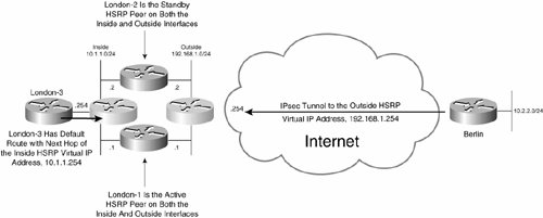
In Figure 7-36, Berlin has established an IPsec tunnel to the outside HSRP virtual IP address, 192.168.1.254. Because London-1 is the active HSRP peer on the outside interface, it is the endpoint of the IPsec tunnel.
An HSRP group is also configured on London-1 and London-2's inside interfaces. London-3 has a default route to the inside HSRP virtual IP address 10.1.1.254, and because London-1 is also the active HSRP peer on the inside interface, user traffic outbound to the Berlin network is forwarded via London-1.
Example 7-41 shows the configuration of London-1.
Example 7-41. Configuration of London-1 for Stateless IPsec High Availability
London-1#show running-config Building configuration... ! hostname London-1 ! crypto isakmp policy 10 authentication pre-share crypto isakmp key cisco address 192.168.2.2 crypto isakmp keepalive 10 ! ! crypto ipsec transform-set mjlnettransform esp-des esp-sha-hmac ! crypto map mjlnetmap 10 ipsec-isakmp set peer 192.168.2.2 set transform-set mjlnettransform match address 101 ! ! ! Inside interface ! interface FastEthernet0/0 ip address 10.1.1.1 255.255.255.0 standby 10 ip 10.1.1.254 (line 1) standby 10 priority 120 (line 2) standby 10 preempt (line 3) standby 10 name ipsecfailover1 (line 4) standby 10 track FastEthernet3/0 50 (line 5) ! ! ! Outside interface ! interface FastEthernet3/0 ip address 192.168.1.1 255.255.255.0 standby 20 ip 192.168.1.254 standby 20 priority 120 standby 20 preempt standby 20 name ipsecfailover standby 20 track FastEthernet0/0 50 crypto map mjlnetmap redundancy ipsecfailover ! access-list 101 permit ip 10.1.1.0 0.0.0.255 10.2.2.0 0.0.0.255 ! |
The configuration of London-1 with HSRP on the inside interface (FastEthernet 0/0) is similar to that with RRI (see Example 7-30)the only difference is the obvious removal of RRI (and EIGRP) and the configuration of HSRP on the inside interface.
Highlighted lines 1 to 5 shows the HSRP configuration on the inside interface.
The configuration of inside interface FastEthernet 0/0 is similar to that for outside interface FastEthernet 3/0. Notice in line 2 that the HSRP priority on the inside interface (120, configured using the standby [group-number] priority priority command) is identical to that configured on outside interface FastEthernet 3/0. The configuration of consistent HSRP priorities on inside and outside interfaces is important, and ensures that when London-1 is the active HSRP peer on the outside interface, it will also be the active HSRP peer on the inside interface. If one router is not the active HSRP on both inside and outside interfaces, user traffic will be black-holed (dropped).
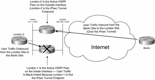
Figure 7-37 illustrates the black-holing of user traffic when one router is not the active HSRP peer on both interfaces.
Figure 7-37. User Traffic Is Black-Holed if One Router Is Not the Active HSRP Peer on Both Interfaces
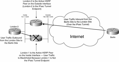
In Figure 7-37, London-1 is the active HSRP peer on its inside interface, and London-2 is the active HSRP peer on the outside interface. User traffic inbound from the Berlin site to the London site is forwarded via London-2 because London-2 is the active HSRP peer on the outside interface.
User traffic outbound from the London site is forwarded via London-1 because London-1 is the active HSRP peer on the inside interface. Because London-1 is not the endpoint of the IPsec tunnel to the Berlin site (it is not the active HSRP peer on the outside interface), user traffic is block-holed on London-1. Not good.
To ensure that user traffic is not black-holed, you must ensure that one router is the active HSRP peer on both inside and outside interfaces.
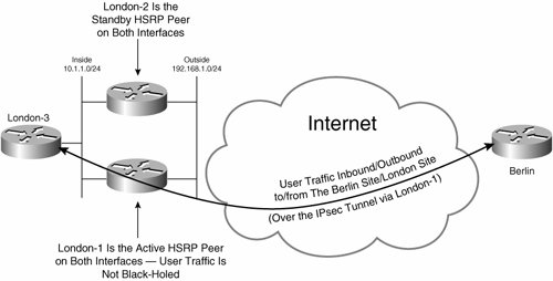
Figure 7-38 illustrates user traffic flow when one router is the active HSRP on both interfaces.
Figure 7-38. User Traffic Is Not Black-Holed If One Router Is the Active HSRP Peer on Both Interfaces
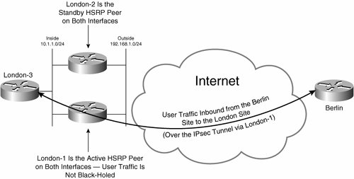
In Figure 7-38, London-1 is the active HSRP peer on both inside and outside interfaces, and is therefore responsible for forwarding both inbound and outbound user traffic. User traffic is therefore not black-holed.
Highlighted lines 1 and 3 in Example 7-41 show the standby [group-number] ip [virtual-IP-address] and standby [group-number] preempt commands. Both of these commands have been previously described, but note that the standby [group-number] ip virtual-IP-address command here configures a virtual IP address for the inside HSRP group of 10.1.1.254.
In highlighted line 4 in Example 7-41, the standby [group-name] name command is used to specify the HSRP name on the inside interface (ipsecfailover1 in this example).
The standby [group-number] track command on the inside interface (highlighted line 5 in Example 7-41) is used to track the status of the outside interface. This command ensures that if the outside interface goes down the HSRP priority on London-1's inside interface will be reduced by 50 (from the default priority of 120 to 70), and because London-2 will then have a higher priority on the outside interface (HSRP priority of 110), London-2 will become active on the inside. If London-1's outside interface goes down, London-2 will also, of course, be the active HSRP peer on the outside interface, and so user traffic will not be black-holed.
Example 7-42 shows the configuration of London-2.
Example 7-42. Configuration of London-2 for Stateless IPsec High Availability
London-2#show running-config Building configuration... ! hostname London-2 ! crypto isakmp policy 10 authentication pre-share crypto isakmp key cisco address 192.168.2.2 crypto isakmp keepalive 10 ! crypto ipsec transform-set mjlnettransform esp-des esp-sha-hmac ! crypto map mjlnetmap 10 ipsec-isakmp set peer 192.168.2.2 set transform-set mjlnettransform match address 101 ! ! ! Inside interface ! interface FastEthernet1/0 ip address 10.1.1.2 255.255.255.0 standby 10 priority 110 (line 1) standby 10 ip 10.1.1.254 standby 10 preempt standby 10 name ipsecfailover1 standby 10 track FastEthernet2/0 50 ! ! ! Outside interface ! interface FastEthernet2/0 ip address 192.168.1.2 255.255.255.0 standby 10 priority 110 (line 2) standby 20 ip 192.168.1.254 standby 20 preempt standby 20 name ipsecfailover2 standby 20 track FastEthernet1/0 50 crypto map mjlnetmap redundancy ipsecfailover2 ! access-list 101 permit ip 10.1.1.0 0.0.0.255 10.2.2.0 0.0.0.255 ! |
As you can see, the configuration of London-2 is almost identical to that for London-1. But, there are one or two differences. As you can see in highlighted lines 1 and 2, an HSRP priority of 110 is configured on both the inside and outside interfaces of London-2. Again, it is important that the HSRP priority be consistent on inside and outside interfaces to ensure that traffic is not black-holed. The HSRP priority on London-2 (110) is lower than that configured on London-1 (120), and so in normal operation, London-1 will be the active HSRP peer and IPsec tunnel endpoint.
When stateless IPsec high availability is configured with HSRP on the inside interface, London-3 should be configured with a default route (or specific a static route to the remote site network, 10.2.2.0/24) with a next hop of the inside HSRP group's virtual IP address. Example 7-43 shows the routing table on London-3.
Example 7-43. Routing Table on London-3 When Stateless IPsec High Availability with HSRP on the Inside Interface Is Configured on London-1 and London-2
London-3#show ip route Codes: C - connected, S - static, I - IGRP, R - RIP, M - mobile, B - BGP D - EIGRP, EX - EIGRP external, O - OSPF, IA - OSPF inter area N1 - OSPF NSSA external type 1, N2 - OSPF NSSA external type 2 E1 - OSPF external type 1, E2 - OSPF external type 2, E - EGP i - IS-IS, L1 - IS-IS level-1, L2 - IS-IS level-2, ia - IS-IS inter area * - candidate default, U - per-user static route, o - ODR P - periodic downloaded static route Gateway of last resort is 10.1.1.254 to network 0.0.0.0 10.0.0.0/24 is subnetted, 2 subnets C 10.1.3.0 is directly connected, Loopback0 C 10.1.1.0 is directly connected, Vlan1 S* 0.0.0.0/0 [1/0] via 10.1.1.254 London-3# |
The highlighted line indicates a static default route with a next hop of the inside HSRP group's virtual IP address. Because the next hop is the HSRP virtual IP address on the inside network, outbound user traffic will be forwarded via London-1 or London-2 depending on which is the active HSRP peer.
Stateful IPsec High Availability
Stateless IPsec high availability is fine if you can tolerate losing a certain amount of user traffic as IKE is renegotiated when the (previously) active HSRP router fails. But, what if you cannot or do not want to tolerate this loss of user traffic? The solution is stateful IPsec high availability.
Remember that when using stateless IPsec high availability, standby HSRP peers do not maintain any IPsec state. That is, standby HSRP peers do not maintain IKE or IPsec SA information. The lack of IPsec state on the standby HSRP peer is the reason that IKE must be renegotiated, and some user traffic is lost.
When using stateful IPsec high availability, IPsec state, including IKE and IPsec SAs, is replicated to the standby HSRP peer, and so failover is instantaneous, and little user traffic is lost.
Figure 7-39 illustrates failover of the IPsec tunnel from the active HSRP peer to the standby HSRP peer when using stateful IPsec high availability.
Figure 7-39. Stateful IPsec High Availability Failover
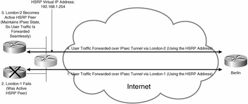
In Figure 7-39, the following sequence of events occurs:
|
1. |
User traffic is being forwarded over an IPsec tunnel from Berlin via London-1 using the HSRP virtual IP address (192.168.1.254). London-1 is the active HSRP peer. |
|
2. |
London-1 then fails. |
|
3. |
London-2 takes over as the active HSRP peer. |
|
4. |
User traffic is now forwarded over an IPsec tunnel from Berlin via London-2 using the HSRP virtual IP address. Because IPsec state is maintained on London-2, it is able to take over as the endpoint of the IPsec tunnel seamlessly, and little or no user traffic is lost. |
As already mentioned, the reason that failover is seamless when using stateful IPsec high availability is that IPsec state is replicated to the standby HSRP peer. Failover with IPsec state replication is achieved via the stateful switchover (SSO) mechanism.
Note
It is also possible to configure IPsec high availability using the State Synchronization Protocol (SSP). SSP was intended to provide stateful failover for IPsec only, whereas SSO can provide stateful failover for a number of protocols, including IPsec. SSO is the preferred method of provisioning IPsec high availability.
There are a few limitations and considerations with stateful IPsec high availability (at the time of this writing):
- Active and standby HSRP peers must run identical Cisco IOS versions.
- The HSRP groups configured on inside and outside interfaces must be configured to track the other interface. That is, the HSRP group on the outside interface must be configured to track the inside interface, and the HSRP group on the inside interface must be configured to track the outside interface.
- The IP addresses configured on the outside and inside interfaces on HSRP peers must be consistently either higher or lower than those of other peers. IP addresses must be configured in this way to ensure that if an HSRP router is the active peer on the outside interface, it will also be the active peer on the inside interface. If a router is the active HSRP peer on the outside interface but not on the inside interface, traffic forwarding will fail (traffic would be black-holed).
- It is a good idea to configure PortFast on ports of switches that connect active and standby HSRP peers on their inside and outside interfaces.
Figure 7-40 illustrates the configuration of stateful IPsec high availability with RRI.
Figure 7-40. Stateful IPsec High Availability Failover with RRI
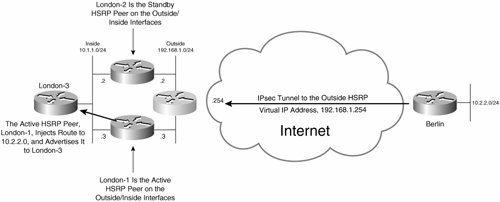
In Figure 7-40, there is an IPsec tunnel between Berlin and the outside HSRP virtual IP address, 192.168.1.254. Because London-1 is the active HSRP peer, London-1 is endpoint of the IPsec tunnel. Additionally, London-1, being the active HSRP peer, injects a static route to the Berlin network (10.2.2.0/24) into its routing table (using RRI) and then redistributes the route into a dynamic routing protocol and advertises it to London-3.
If you do not want to use a dynamic routing protocol between the inside router (London-3) and the HSRP peers (London-1 and London-2), you can instead configure a static route on the inside router to the remote network with its next hop being the HSRP virtual IP address on the inside interfaces of the HSRP peers, as illustrated in Figure 7-41.
Figure 7-41. Stateful IPsec High Availability Failover with Static Route(s) Configured on the Inside Router for Reachability to Remote Networks
In Figure 7-41, Berlin has established an IPsec tunnel to the outside HSRP virtual IP address, 192.168.1.254. Because London-1 is the active HSRP peer on the outside interface, it is the endpoint of the IPsec tunnel.
An HSRP group is also configured on London-1's and London-2's inside interfaces. London-3 has a default route with a next hop of the inside HSRP virtual IP address 10.1.1.254, and because London-1 is also the active HSRP peer on the inside interface, user traffic outbound to the Berlin network is forwarded via London-1.
Example 7-44 shows the configuration of London-1 when using stateful IPsec high availability with RRI. Note that some of the commands in Example 7-44 have been previously described and so are not reexamined in this section.
Example 7-44. Configuration of London-1 for Stateful IPsec High Availability with RRI
London-1#show running-config Building configuration... ! hostname London-1 ! ! redundancy inter-device (line 1) scheme standby ipsecfailover1 (line 2) security ipsec sso-ipsec (line 3) ! ! ipc zone default (line 4) association 1 (line 5) no shutdown (line 6) protocol sctp (line 7) local-port 4000 (line 8) local-ip 10.1.1.3 (line 9) remote-port 4000 (line 10) remote-ip 10.1.1.2 (line 11) ! ! crypto isakmp policy 10 (line 12) authentication pre-share crypto isakmp key mjlnet address 0.0.0.0 0.0.0.0 no-xauth (line 13) ! ! crypto ipsec transform-set mjlnettransform esp-des esp-sha-hmac (line 14) crypto ipsec transform-set ssotransform esp-aes esp-sha-hmac (line 15) ! crypto ipsec profile sso-ipsec (line 16) set transform-set ssotransform (line 17) ! ! crypto map mjlnetmap redundancy replay-interval inbound 1000 outbound 20000 (line 18) crypto map mjlnetmap 10 ipsec-isakmp (line 19) set peer 192.168.100.10 set transform-set mjlnettransform match address 101 reverse-route (line 20) ! ! interface FastEthernet0/0 description Inside interface ip address 10.1.1.3 255.255.255.0 standby delay reload 120 (line 21) standby 20 ip 10.1.1.254 (line 22) standby 20 preempt (line 23) standby 20 name ipsecfailover1 (line 24) standby 20 track FastEthernet1/0 (line 25) ! interface FastEthernet1/0 description Outside interface ip address 192.168.1.3 255.255.255.0 standby delay reload 120 (line 26) standby 10 ip 192.168.1.254 (line 27) standby 10 preempt (line 28) standby 10 name ipsecfailover2 (line 29) standby 10 track FastEthernet0/0 (line 30) crypto map mjlnetmap redundancy ipsecfailover2 stateful (line 31) ! ! ! router ospf 100 redistribute static metric 10 subnets (line 32) network 10.1.1.0 0.0.0.255 area 0 ! ip route 0.0.0.0 0.0.0.0 192.168.1.10 (line 33) ! access-list 101 permit ip 10.1.1.0 0.0.0.255 10.2.2.0 0.0.0.255 ! |
Highlighted lines 1 to 3 show the configuration of redundancy.
The redundancy inter-device command in highlighted line 1 is used to begin the configuration of interdevice redundancy.
In line 2, the scheme standby standby-group-name command configures the redundancy scheme (standby [HSRP]) and links to the standby (HSRP) group name configured on London-1's inside interface (ipsecfailover1).
Line 3 shows the security ipsec profile-name command. This command links to an IPsec profile that is used to protect SSO information as it is exchanged between the redundancy group (London-1 and London-2). The security ipsec command is recommended but is not absolutely essential if you are sure that the interfaces on which SSO information is exchanged are secure.
The configuration of the interdevice communication protocol (IPC) is shown in lines 4 to 11.
The ipsec zone default command (line 4) begins the configuration of IPC and enters IPC zone configuration mode.
In line 5, the association 1 command is used to specify an IPC association between London-1 and London-2.
The protocol sctp command (line 7) then configures the Stream Control Transmission Protocol (SCTP, RFC2960) as the transport protocol for communication between London-1 and London-2.
Next, the local-port local-port-number, local-ip ip-address, remote-port remote-port-number, and remote-ip ip-address commands in lines 8 to 11 are used to configure the local SCTP port, local device interface IP address (inside interface), remote SCTP port, and remote device interface IP address (inside interface), respectively. The local SCTP port number should be the same as the remote SCTP port on the peer device (London-2 in this case), and the remote SCTP port number should be the same as the local SCTP port number on the peer device.
The no shutdown command in line 6 then enables London-1 to begin communication with London-2.
Lines 12 to 14 show the configuration of the IKE (ISAKMP) policy, preshared key, and IPsec transform set (used to encrypt and authenticate traffic sent between London and Berlin).
In line 15, an IPsec transform set is configured to encrypt and authenticate SSO traffic as it is exchanged between London-1 and London-2.
The crypto ipsec profile profile-name command (line 16) begins the configuration of an IPsec profile that is used to protect SSO traffic, and the set transform-set transform-set-name command (line 17) references the transform set configured in line 15.
The intervals at which IPsec anti-replay information is replicated between London-1 and London-2 is now specified in line 18 using the crypto map map-name redundancy replay-interval inbound in-value outbound out-value command.
The in-value and out-value parameters are used to configure the number of inbound and outbound IPsec packets (received from/sent to the remote IPsec peer) that are processed before the anti-replay information is sent to the standby peer in the redundancy group.
The crypto map is then configured beginning in line 19, and the reverse-route command (line 20) is then used to inject a static route to the remote network (Berlin's inside network) on the active peer in the redundancy group.
Configuration of the HSRP groups on London-1's inside interface (FastEthernet 0/0) is next.
In line 21, you can see the command standby [group-number] delay minimum [min-delay] reload [reload-delay], which ensures that if a router interface that was previously in a down state comes up, or the router is reloaded, it does not immediately become the active HSRP peer (assuming its HSRP priority or IP address would cause this) but instead waits for the periods specified. These waiting periods ensure that HSRP packets are received from HSRP peers before any HSRP state change to active.
Next are the standby group-number ip ip-address and standby group-number preempt (lines 22 and 23) commands. These commands are used to configure the virtual IP address and preemption for the HSRP group, respectively.
The standby [group-number] name group-name command in line 24 configures the inside interface HSRP group name (ipsecfailover1 in this example).
The final command on inside interface FastEthernet 0/0 is standby [group-number] track interface (line 25). This command configures London-1 to monitor the status of the outside interface (FastEthernet1/0 in this example) and decrements the (default) inside HSRP priority of 100 by 10 if the outside interface goes down. 10 is the default decrement, and so it is not shown.
Lines 26 to 30 show the configuration of HSRP on the outside interface (FastEthernet 1/0). The key differences with the HSRP configuration of the inside interface are (obviously) the HSRP virtual IP address, as well as the HSRP group name (ipsecfailover2 as opposed to ipsecfailover1 on the inside interface). Also notice that the standby group-number track interface command is used in this case to track the inside interface and decrement the (default) outside HSRP priority of 100 by 10 if the inside interface goes down.
The result of the HSRP interface tracking configuration on the inside and outside interfaces is that either London-1 or London-2 will always be the active HSRP peer for both inside and outside interfaces.
If one router (either London-1 or London-2) is not the active HSRP peer on both inside and outside interfaces, user traffic might be black-holed (dropped).
Figure 7-42 illustrates the black-holing of user traffic when one router is not the active HSRP peer on both interfaces.
Figure 7-42. User Traffic Is Black-Holed If One Router Is Not the Active HSRP Peer on Both Interfaces
In Figure 7-42, London-1 is the active HSRP peer on its inside interface, and London-2 is the active HSRP peer on the outside interface. User traffic inbound from the Berlin site to the London site is forwarded via London-2 because London-2 is the active HSRP peer on the outside interface. User traffic outbound from the London site is forwarded via London-1 because London-1 is the active HSRP peer on the inside interface. Because London-1 is not the endpoint of the IPsec tunnel to the Berlin site (it is not the active HSRP peer on the outside interface), user traffic is black-holed on London-1.
So, to ensure that user traffic is not black-holed, you must ensure that one router is the active HSRP peer on both inside and outside interfaces (which is the effect of the configurations in Examples 7-44 and 7-45).
Figure 7-43 illustrates user traffic flow when one router is the active HSRP peer on both interfaces.
Figure 7-43. User Traffic Is Not Black-Holed If One Router Is the Active HSRP Peer on Both Interfaces
In Figure 7-43, London-1 is the active HSRP peer on both inside and outside interfaces, and is therefore responsible for forwarding both inbound and outbound user traffic. User traffic is not black-holed.
Returning to the configuration in Example 7-44, the crypto map map-name [redundancy standby-group-name [stateful]] command in highlighted line 31 binds the crypto map configured in highlighted line 19 to the redundancy group and specifies that failover will be stateful. Note that the standby group name configured using this command must match that specified using the standby name command (ipsecfailover2).
Highlighted line 32 in Example 7-44 shows the redistribution of the static route to the Berlin network (which is injected into routing table via RRI on the active HSRP peer) into the routing protocol used on the inside network (OSPF in this example).
In highlighted line 33, a static default route is used to provide reachability to Berlin.
Example 7-45 shows the configuration of London-2.
Example 7-45. Configuration of London-2 for Stateful IPsec High Availability with RRI
London-2#show running-config Building configuration... ! hostname London-2 ! ! redundancy inter-device scheme standby ipsecfailover1 security ipsec sso-ipsec ! ! ipc zone default association 1 no shutdown protocol sctp local-port 4000 local-ip 10.1.1.2 (line 1) remote-port 4000 remote-ip 10.1.1.3 (line 2) ! ! crypto isakmp policy 10 authentication pre-share crypto isakmp key mjlnet address 0.0.0.0 0.0.0.0 no-xauth ! ! crypto ipsec transform-set mjlnettransform esp-des esp-sha-hmac crypto ipsec transform-set ssotransform esp-aes esp-sha-hmac ! crypto ipsec profile sso-ipsec set transform-set ssotransform ! ! crypto map mjlnetmap redundancy replay-interval inbound 1000 outbound 20000 crypto map mjlnetmap 10 ipsec-isakmp set peer 192.168.100.10 set transform-set mjlnettransform match address 101 reverse-route ! ! interface FastEthernet0/0 description Inside interface ip address 10.1.1.2 255.255.255.0 (line 3) standby delay reload 120 standby 20 ip 10.1.1.254 standby 20 preempt standby 20 name ipsecfailover1 standby 20 track FastEthernet2/0 ! interface FastEthernet2/0 description Outside interface ip address 192.168.1.2 255.255.255.0 (line 4) standby delay reload 120 standby 10 ip 192.168.1.254 standby 10 preempt standby 10 name ipsecfailover2 standby 10 track FastEthernet0/0 crypto map mjlnetmap redundancy ipsecfailover2 stateful ! ! router ospf 100 redistribute static metric 10 subnets network 10.1.1.0 0.0.0.255 area 0 ! ! ip route 0.0.0.0 0.0.0.0 192.168.1.10 ! access-list 101 permit ip 10.1.1.0 0.0.0.255 10.2.2.0 0.0.0.255 ! |
To a great extent, the configuration of London-2 is the same as that for London-1. The only differences are the local and remote device IP addresses configured in highlighted lines 1 and 2, and the IP addresses configured on the inside and outside interfaces in lines 3 and 4.
That is the configuration of stateful IPsec high availability with RRI. Now it is time to see what happens in operation.
Initially, London-1 is the active HSRP peer and is active as far as SSO is concerned. This is verified using the show standby brief and show redundancy states commands, as demonstrated in Example 7-46.
Example 7-46. Confirming That London-1 Is the Active HSRP Peer on Its Outside Interfaces
London-1#show standby brief P indicates configured to preempt. | Interface Grp Prio P State Active Standby Virtual IP Fa0/0 20 100 P Active local 10.1.1.2 10.1.1.254 (line 1) Fa1/0 10 100 P Active local 192.168.1.2 192.168.1.254 (line 2) London-1# London-1# London-1#show redundancy states my state = 13 -ACTIVE (line 3) peer state = 8 -STANDBY HOT (line 4) Mode = Duplex Unit ID = 0 Split Mode = Disabled Manual Swact = Enabled Communications = Up client count = 8 client_notification_TMR = 30000 milliseconds RF debug mask = 0x0 London-1# |
Highlighted line 1 shows that the HSRP state on London-1's inside interface (FastEthernet 0/0) is Active. The IP of the standby HSRP peer is also shown (London-2, 10.1.1.2), along with the HSRP virtual IP address (10.1.1.254).
In line 2, you can also see that the HSRP state on London-1's outside interface (FastEthernet 1/0) is Active. The IP address of the standby HSRP peer is again shown (London-2, 192.168.1.2) as well as the virtual IP address (192.168.1.254).
The virtual IP address on the outside interface is used as the IPsec tunnel endpoint, and because London-1 is the active HSRP peer on the outside, London-1 terminates the IPsec tunnel.
The output of the show redundancy states command (lines 3 and 4) confirms that the local router is active and that the peer (London-2) is in a hot-standby state.
When using stateful IPsec high availability, IPsec state is maintained on both the active HSRP peer (London-1) and the standby HSRP peer (London-2). This is clearly illustrated in the output of the show crypto isakmp ha active and show crypto ipsec sa commands in Example 7-47.
Example 7-47. show crypto isakmp ha active and show crypto ipsec sa Command Output on London-1
London-1#show crypto isakmp sa active
dst src state conn-id slot status
192.168.1.254 192.168.100.10 QM_IDLE 2 0 ACTIVE (line 1)

London-1#
London-1#
London-1#show crypto ipsec sa active

interface: FastEthernet1/0
 Crypto map tag: mjlnetmap, local addr 192.168.1.254

 protected vrf: (none)
 local ident (addr/mask/prot/port): (10.1.1.0/255.255.255.0/0/0)
 remote ident (addr/mask/prot/port): (10.2.2.0/255.255.255.0/0/0)
 current_peer 192.168.100.10 port 500
 PERMIT, flags={origin_is_acl,}
 #pkts encaps: 4, #pkts encrypt: 4, #pkts digest: 4
 #pkts decaps: 5, #pkts decrypt: 5, #pkts verify: 5
 #pkts compressed: 0, #pkts decompressed: 0
 #pkts not compressed: 0, #pkts compr. failed: 0
 #pkts not decompressed: 0, #pkts decompress failed: 0
 #send errors 0, #recv errors 0

 local crypto endpt.: 192.168.1.254, remote crypto endpt.:
 192.168.100.10 (line 2)
 path mtu 1500, ip mtu 1500
 current outbound spi: 0xC8A8EE8C(3366514316)

 inbound esp sas: (line 3)
 spi: 0xDFC85091(3754446993)
 transform: esp-des esp-sha-hmac ,
 in use settings ={Tunnel, }
 conn id: 2005, flow_id: SW:5, crypto map: mjlnetmap
 sa timing: remaining key lifetime (k/sec): (4449849/3032)
 HA KB life last checkpointed at (k): (4449850)
 IV size: 8 bytes
 replay detection support: Y
 Status: ACTIVE

 inbound ah sas:

 inbound pcp sas:

 outbound esp sas: (line 4)
 spi: 0xC8A8EE8C(3366514316)
 transform: esp-des esp-sha-hmac ,
 in use settings ={Tunnel, }
 conn id: 2006, flow_id: SW:6, crypto map: mjlnetmap
 sa timing: remaining key lifetime (k/sec): (4449849/3031)
 HA KB life last checkpointed at (k): (4449850)
 IV size: 8 bytes
 replay detection support: Y
 Status: ACTIVE

 outbound ah sas:

 outbound pcp sas:
London-1#
|
Highlighted line 1 shows the IKE SAs for which London-1 is currently the active peer. In this case, London-1 is active for an IKE (ISAKMP) SA with IPsec peer 192.168.100.10 (Berlin). IKE SA information shown includes IKE state (QM_IDLEIKE phase 1 is complete, and phase 2 [quick mode] is in an idle state).
Below lines 3 and 4, you can see the inbound and outbound IPsec (ESP) SAs established between the HSRP virtual IP address 192.168.1.254 (London-1, as the HSRP active peer), and 192.168.100.10 (Berlin, see line 2).
Because London-1 and London-2 are configured as stateful IPsec high-availability peers, IKE and IPsec SA information is replicated from the active HSRP peer, London-1, to the standby HSRP peer, London-2. You can verify this replication of SA information using the show crypto isakmp ha standby and show crypto ipsec sa standby commands on London-2, as demonstrated in Example 7-48.
Example 7-48. show crypto isakmp ha standby and show crypto ipsec sa Command Output on London-2
London-2#show crypto isakmp sa standby
dst src state conn-id slot status
192.168.1.254 192.168.100.10 QM_IDLE 2 0 STDBY (line 1)

London-2#
London-2#
London-2#show crypto ipsec sa standby

interface: FastEthernet2/0
 Crypto map tag: mjlnetmap, local addr 192.168.1.254

 protected vrf: (none)
 local ident (addr/mask/prot/port): (10.1.1.0/255.255.255.0/0/0)
 remote ident (addr/mask/prot/port): (10.2.2.0/255.255.255.0/0/0)
 current_peer 192.168.100.10 port 500
 PERMIT, flags={origin_is_acl,}
 #pkts encaps: 0, #pkts encrypt: 0, #pkts digest: 0
 #pkts decaps: 0, #pkts decrypt: 0, #pkts verify: 0
 #pkts compressed: 0, #pkts decompressed: 0
 #pkts not compressed: 0, #pkts compr. failed: 0
 #pkts not decompressed: 0, #pkts decompress failed: 0
 #send errors 0, #recv errors 0

 local crypto endpt.: 192.168.1.254, remote crypto endpt.: 192.168.100.10
 path mtu 1500, ip mtu 1500
 current outbound spi: 0xC8A8EE8C(3366514316)

 inbound esp sas: (line 2)
 spi: 0xDFC85091(3754446993)
 transform: esp-des esp-sha-hmac ,
 in use settings ={Tunnel, }
 conn id: 2005, flow_id: SW:5, crypto map: mjlnetmap
 sa timing: remaining key lifetime (k/sec): (4131229/2938)
 HA KB life last update received (k): (4131229)
 IV size: 8 bytes
 replay detection support: Y
 Status: STANDBY (line 3)

 inbound ah sas:

 inbound pcp sas:

 outbound esp sas: (line 4)
 spi: 0xC8A8EE8C(3366514316)
 transform: esp-des esp-sha-hmac ,
 in use settings ={Tunnel, }
 conn id: 2006, flow_id: SW:6, crypto map: mjlnetmap
 sa timing: remaining key lifetime (k/sec): (4131229/2937)
 HA KB life last update received (k): (4131229)
 IV size: 8 bytes
 replay detection support: Y
 Status: STANDBY (line 5)

 outbound ah sas:

 outbound pcp sas:
London-2#
|
Highlighted line 1 shows the IKE SAs for which London-2 is currently the standby peer. IKE SA information is replicated from the active peer, London-1.
Below line 2, you can see that the inbound IPsec (ESP) SA has again been replicated to London-2 from London-1. Line 3 shows that this SA is in a standby state.
Similarly, in lines 4 and 5, you can see the outbound IPsec (ESP) SA, and the fact that it is in a standby state.
Okay, so HSRP and IPsec state replication are operating as expected. But how about RRI? Example 7-49 shows the output of the show ip route command on London-3 when London-1 is the active HSRP peer.
Example 7-49. IP Routing Table on London-1 When London-1 Is the Active HSRP Peer
London-3#show ip route Codes: C - connected, S - static, I - IGRP, R - RIP, M - mobile, B - BGP D - EIGRP, EX - EIGRP external, O - OSPF, IA - OSPF inter area N1 - OSPF NSSA external type 1, N2 - OSPF NSSA external type 2 E1 - OSPF external type 1, E2 - OSPF external type 2, E - EGP i - IS-IS, L1 - IS-IS level-1, L2 - IS-IS level-2, ia - IS-IS inter area * - candidate default, U - per-user static route, o - ODR Gateway of last resort is not set 10.0.0.0/8 is variably subnetted, 4 subnets, 2 masks O E2 10.1.1.2/32 [110/10] via 10.1.1.3, 00:09:44, Ethernet0 O E2 10.2.2.0/24 [110/10] via 10.1.1.3, 00:03:17, Ethernet0 C 10.1.1.0/24 is directly connected, Ethernet0 O E2 10.1.1.1/32 [110/10] via 10.1.1.2, 00:09:44, Ethernet0 192.168.1.0/32 is subnetted, 1 subnets O E2 192.168.1.10 [110/10] via 10.1.1.3, 00:03:17, Ethernet0 London-3# |
The highlighted line indicates that a route to network 10.2.2.0/24 (Berlin) has been installed into London-3's routing table. Notice that the route is via 10.1.1.3 (London-1, the active HSRP peer).
All well and goodeverything seems to be operating as expected with London-1 as the active HSRP peer. Now take a look at what happens when London-1 fails.
When London-1 fails, the messages shown in Example 7-50 are logged on London-2.
Example 7-50. Messages Logged on London-2 When London-1 Fails
London-2# *Nov 16 22:39:10.363: %HSRP-6-STATECHANGE: FastEthernet0/0 Grp 20 state Standby -> Active (line 1) *Nov 16 22:39:10.363: %HSRP-6-STATECHANGE: FastEthernet2/0 Grp 10 state Standby -> Active (line 2) *Nov 16 22:39:10.367: %CRYPTO-5-IKE_SA_HA_STATUS: IKE sa's if any, for vip 192.168.1.254 will change from STANDBY to ACTIVE (line 3) *Nov 16 22:39:10.371: %CRYPTO-5-IPSEC_SA_HA_STATUS: IPSec sa's if any, for vip 192.168.1.254 will change from STANDBY to ACTIVE (line 4) London-2# |
In line 1, the HSRP state changes from standby to active on London-2's interface FastEthernet 0/0. So, London-2 is now the active HSRP peer on the inside interface.
In line 2, London-2 takes over as the active HSRP peer on its outside interface (FastEthernet 2/0).
London-2 takes over as the active device for IKE on the HSRP virtual IP address 192.168.1.254 in line 3.
Then, in line 4, London-2 takes over as the active device for IPsec on the HSRP virtual IP address 192.168.1.254. London-2 is now the endpoint of the IPsec tunnel to Berlin.
London-2 is the IPsec tunnel endpoint, and because IPsec state has been maintained on London-2, it is ready to seamlessly forward user traffic over the IPsec tunnel without having to renegotiate IKE with Berlin.
A quick check of the IKE and IPsec SAs using the show crypto isakmp ha active and show crypto ipsec sa active commands confirms that the SAs are now active on London-2, as demonstrated in Example 7-51.
Example 7-51. show crypto isakmp ha active and show crypto ipsec sa Command Output on London-2
London-2#show crypto isakmp sa active
dst src state conn-id slot status
192.168.1.254 192.168.100.10 QM_IDLE 2 0 ACTIVE (line 1)

London-2#
London-2#
London-2#show crypto ipsec sa active

interface: FastEthernet2/0
 Crypto map tag: mjlnetmap, local addr 192.168.1.254

 protected vrf: (none)
 local ident (addr/mask/prot/port): (10.1.1.0/255.255.255.0/0/0)
 remote ident (addr/mask/prot/port): (10.2.2.0/255.255.255.0/0/0)
 current_peer 192.168.100.10 port 500
 PERMIT, flags={origin_is_acl,}
 #pkts encaps: 0, #pkts encrypt: 0, #pkts digest: 0
 #pkts decaps: 0, #pkts decrypt: 0, #pkts verify: 0
 #pkts compressed: 0, #pkts decompressed: 0
 #pkts not compressed: 0, #pkts compr. failed: 0
 #pkts not decompressed: 0, #pkts decompress failed: 0
 #send errors 0, #recv errors 0

 local crypto endpt.: 192.168.1.254, remote crypto endpt.: 192.168.100.10
 path mtu 1500, ip mtu 1500
 current outbound spi: 0xC8A8EE8C(3366514316)

 inbound esp sas: (line 2)
 spi: 0xDFC85091(3754446993)
 transform: esp-des esp-sha-hmac ,
 in use settings ={Tunnel, }
 conn id: 2005, flow_id: SW:5, crypto map: mjlnetmap
 sa timing: remaining key lifetime (k/sec): (3815107/2209)
 HA KB life last checkpointed at (k): (3815107)
 IV size: 8 bytes
 replay detection support: Y
 Status: ACTIVE (line 3)

 inbound ah sas:
 inbound pcp sas:

 outbound esp sas: (line 4)
 spi: 0xC8A8EE8C(3366514316)
 transform: esp-des esp-sha-hmac ,
 in use settings ={Tunnel, }
 conn id: 2006, flow_id: SW:6, crypto map: mjlnetmap
 sa timing: remaining key lifetime (k/sec): (3815107/2207)
 HA KB life last checkpointed at (k): (3815107)
 IV size: 8 bytes
 replay detection support: Y
 Status: ACTIVE (line 5)

 outbound ah sas:

 outbound pcp sas:
London-2#
|
Highlighted line 1 confirms that London-2 is now the active peer for the IKE SA established to Berlin (192.168.100.10).
Below lines 2 and 4, you can see the inbound and outbound IPsec (ESP) SAs established with Berlin. Lines 3 and 5 show that these SAs are now in an active state.
A look at the routing table on London-3 reveals that London-2 (10.1.1.2) is now the next hop of the route to the Berlin network (10.2.2.0/24) (see Example 7-52).
Example 7-52. IP Routing Table on London-2 When London-2 Has Taken Over as the Active HSRP Peer
London-3#show ip route Codes: C - connected, S - static, I - IGRP, R - RIP, M - mobile, B - BGP D - EIGRP, EX - EIGRP external, O - OSPF, IA - OSPF inter area N1 - OSPF NSSA external type 1, N2 - OSPF NSSA external type 2 E1 - OSPF external type 1, E2 - OSPF external type 2, E - EGP i - IS-IS, L1 - IS-IS level-1, L2 - IS-IS level-2, ia - IS-IS inter area * - candidate default, U - per-user static route, o - ODR Gateway of last resort is not set 10.0.0.0/8 is variably subnetted, 3 subnets, 2 masks O E2 10.2.2.0/24 [110/10] via 10.1.1.2, 00:00:14, Ethernet0 (line 1) C 10.1.1.0/24 is directly connected, Ethernet0 O E2 10.1.1.1/32 [110/10] via 10.1.1.2, 00:00:14, Ethernet0 192.168.1.0/32 is subnetted, 1 subnets O E2 192.168.1.10 [110/10] via 10.1.1.2, 00:00:15, Ethernet0 mjlnet.Los.Angeles.CE# London-2# |
In the highlighted line, you can see a route to the Berlin network. London-2 is now the active HSRP peer, so RRI is injecting a static route to the Berlin network, and this route is being redistributed and advertised to London-3.
High Availability with GRE
An alternative method of provisioning high availability for IPsec VPNs is to use GRE tunnels. High availability for IPsec VPNs using GRE can be provisioned in two ways:
- Using point-to-point GRE tunnels
- Using multipoint GRE tunnels (with DMVPN)
The following two sections examine high availability with GRE tunnels.
High Availability with Point-to-Point GRE Tunnels
One way to ensure high availability for IPsec VPNs is to configure two point-to-point GRE tunnels from each spoke site, with one GRE tunnel terminating on one hub site gateway, and the other GRE tunnel terminating on another hub site gateway.
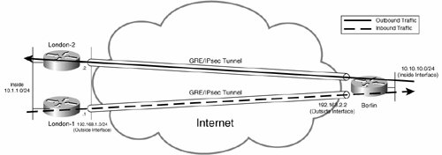
Figure 7-44 illustrates high availability with point-to-point GRE tunnels for a single-spoke gateway.
Figure 7-44. High Availability with Point-to-Point GRE Tunnels
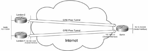
In Figure 7-44, the Berlin gateway is configured with one point-to-point GRE tunnel to the London-1 gateway and one point-to-point GRE tunnel to the London-2. Both GRE tunnels are constantly in an up state, and so if either London-1 or London-2 fails, the spoke Berlin gateway maintains connectivity to the London site via the other hub site London gateway.
Figure 7-45 shows point-to-point GRE tunnels from a number of spoke site gateways.
Figure 7-45. High Availability with Point-to-Point GRE Tunnels from a Number of Spoke Site Gateways
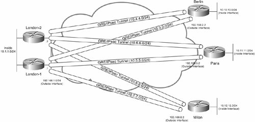
In Figure 7-45, the Berlin, Paris, and Milan spoke gateways each have two GRE tunnels configured, one to the London-1 hub site gateway and one to the London-2 hub site gateway.
Example 7-53 shows the configuration of the London-1 and London-2 hub site gateways.
Example 7-53. Configuration of the London-1 and London-2 Hub Site Gateways
London-1#show running-config
Building configuration...
!
! London-1 gateway configuration
!
!
! IKE policy
!
crypto isakmp policy 10
 authentication pre-share
!
!
! Pre-shared keys (one per spoke gateway)
!
crypto isakmp key mjlnet1 address 192.168.2.2
crypto isakmp key mjlnet2 address 192.168.5.2
crypto isakmp key mjlnet3 address 192.168.8.2
!
!
! IPsec transform set
!
crypto ipsec transform-set mjlnettrans esp-3des esp-sha-hmac
!
!
! Crypto map entries (one per spoke gateway)
!
crypto map mjlnetmap 10 ipsec-isakmp
 set peer 192.168.2.2
 set transform-set mjlnettrans
 match address 101
crypto map mjlnetmap 20 ipsec-isakmp
 set peer 192.168.5.2
 set transform-set mjlnettrans
 match address 102
crypto map mjlnetmap 30 ipsec-isakmp
 set peer 192.168.8.2
 set transform-set mjlnettrans
 match address 103
!
!
! Point-to-point GRE tunnel interfaces (one per spoke gateway)(line 1)
!
interface Tunnel0
 description To Berlin
 ip address 10.3.3.1 255.255.255.0
 tunnel source 192.168.1.1
 tunnel destination 192.168.2.2
!
interface Tunnel1
 description To Paris
 ip address 10.5.5.1 255.255.255.0
 tunnel source 192.168.1.1
 tunnel destination 192.168.5.2
!
interface Tunnel2
 description To Milan
 ip address 10.7.7.1 255.255.255.0
 tunnel source 192.168.1.1
 tunnel destination 192.168.8.2
!
!
! Inside interface
!
interface FastEthernet3/0
 ip address 10.1.1.1 255.255.255.0
!
!
! Outside interface
!
interface Serial1/0
 ip address 192.168.1.1 255.255.255.0
 crypto map mjlnetmap
!
!
! Routing protocol configuration (enable on GRE tunnel interfaces and inside
! interfaces as appropriate) (line 2)
!
router eigrp 100
 network 10.1.1.0 0.0.0.255
 network 10.3.3.0 0.0.0.255
 network 10.5.5.0 0.0.0.255
 network 10.7.7.0 0.0.0.255
 no auto-summary
!
!
! Crypto access lists (one per GRE tunnel)
!
access-list 101 permit gre host 192.168.1.1 host 192.168.2.2
access-list 102 permit gre host 192.168.1.1 host 192.168.5.2
access-list 103 permit gre host 192.168.1.1 host 192.168.8.2
!
!
end
London-2#show running-config Building configuration... ! ! London-2 gateway configuration ! ! ! IKE policy ! crypto isakmp policy 10 authentication pre-share ! ! ! Pre-shared keys (one per spoke gateway) ! crypto isakmp key mjlnet address 192.168.2.2 crypto isakmp key mjlnet address 192.168.5.2 crypto isakmp key mjlnet address 192.168.8.2 ! ! ! IPsec transform set ! crypto ipsec transform-set mjlnettrans esp-3des esp-sha-hmac ! ! ! Crypto map entries (one per spoke gateway) ! crypto map mjlnetmap 10 ipsec-isakmp set peer 192.168.2.2 set transform-set mjlnettrans match address 101 crypto map mjlnetmap 20 ipsec-isakmp set peer 192.168.5.2 set transform-set mjlnettrans match address 102 crypto map mjlnetmap 30 ipsec-isakmp set peer 192.168.8.2 set transform-set mjlnettrans match address 103 ! ! ! Point-to-point GRE tunnel interface (one per spoke gateway) (line 3) ! interface Tunnel0 description To Berlin ip address 10.4.4.1 255.255.255.0 tunnel source 192.168.1.2 tunnel destination 192.168.2.2 ! interface Tunnel1 description To Paris ip address 10.6.6.1 255.255.255.0 tunnel source 192.168.1.2 tunnel destination 192.168.5.2 ! interface Tunnel2 description To Milan ip address 10.8.8.1 255.255.255.0 tunnel source 192.168.1.2 tunnel destination 192.168.8.2 ! ! ! Inside interface ! interface FastEthernet0/0 ip address 10.1.1.10 255.255.255.0 ! ! ! Outside interface ! interface Serial2/0 ip address 192.168.1.2 255.255.255.0 crypto map mjlnetmap ! ! ! Routing protocol configuration (enable on GRE tunnel interfaces and inside ! interfaces as appropriate) (line 4) ! router eigrp 100 network 10.1.1.0 0.0.0.255 network 10.4.4.0 0.0.0.255 network 10.6.6.0 0.0.0.255 network 10.8.8.0 0.0.0.255 no auto-summary ! ! ! Crypto access lists (one per GRE tunnel) ! access-list 101 permit gre host 192.168.1.2 host 192.168.2.2 access-list 102 permit gre host 192.168.1.2 host 192.168.5.2 access-list 103 permit gre host 192.168.1.2 host 192.168.8.2 ! ! end |
As you can see in Example 7-53, the configuration of the London-1 and London-2 hub site gateways is pretty standard. If you find the configuration confusing, you might like to refresh your memory by referring back to the section "Using GRE Tunnels to Carry Multiprotocol and Multicast Traffic Across the IPsec VPN" in Chapter 6.
Notice below highlighted lines 1 and 3 that London-1 and London-2 are configured with one point-to-point GRE tunnel interface per spoke site. Also, notice that EIGRP is configured on the GRE tunnel and inside interfaces of London-1 and London-2 for site-to-site reachability (see below lines 2 and 4). It is also possible to configure another dynamic routing protocol such as OSPF or even use static routes for site-to-site reachability.
Example 7-54 shows the configuration of a spoke site gateway (the Berlin gateway in this example).
Example 7-54. Configuration of the Berlin Spoke Site Gateway
Berlin#show running-config Building configuration... ! ! Berlin gateway configuration ! ! ! IKE policy ! crypto isakmp policy 10 authentication pre-share ! ! ! Pre-shared keys (one per hub site gateway) ! crypto isakmp key mjlnet address 192.168.1.1 crypto isakmp key mjlnet address 192.168.1.2 ! ! ! IPsec transform set ! crypto ipsec transform-set mjlnettrans esp-3des esp-sha-hmac ! ! ! Crypto map entries (one per hub site gateway) ! crypto map mjlnetmap 10 ipsec-isakmp set peer 192.168.1.1 set transform-set mjlnettrans match address 101 crypto map mjlnetmap 20 ipsec-isakmp set peer 192.168.1.2 set transform-set mjlnettrans match address 102 ! ! ! Point-to-point GRE tunnel interface (One per hub site gateway) (line 1) ! interface Tunnel0 description To London-1 ip address 10.3.3.2 255.255.255.0 tunnel source 192.168.2.2 tunnel destination 192.168.1.1 ! interface Tunnel1 description To London-2 ip address 10.4.4.2 255.255.255.0 tunnel source 192.168.2.2 tunnel destination 192.168.1.2 ! ! ! Inside interface ! interface FastEthernet1/0 ip address 10.10.10.1 255.255.255.0 ! ! ! Outside interface ! interface FastEthernet2/0 ip address 192.168.2.2 255.255.255.0 crypto map mjlnetmap ! ! ! Routing protocol configuration (enable on GRE tunnel interfaces and inside ! interfaces as appropriate) (line 2) ! router eigrp 100 network 10.10.10.0 0.0.0.255 network 10.3.3.0 0.0.0.255 network 10.4.4.0 0.0.0.255 no auto-summary ! ! ! Crypto access lists (one per GRE tunnel) ! access-list 101 permit gre host 192.168.2.2 host 192.168.1.1 access-list 102 permit gre host 192.168.2.2 host 192.168.1.2 ! ! ! end |
Below highlighted line 1, you can see the configuration of one GRE tunnel interface per hub site gateway. Then, below highlighted line 2, you can see the configuration of EIGRP on the inside interface and the GRE tunnel interfaces for site-to-site reachability.
The base configurations shown in Examples 7-53 and 7-54 are a good starting point; if asymmetric routing and out-of-order packets are to be avoided, however, you need to add one or two optimizations.
Asymmetric routing and out-of-order packets are caused because of the equal-cost routes that result with the base configurations shown in Examples 7-53 and 7-54. These equal-cost routes are shown in the output of the show ip route command on the Berlin gateway in Example 7-55.
Example 7-55. show ip route Command Output Shows Two Equal-Cost Routes
Berlin#show ip route Codes: C - connected, S - static, R - RIP, M - mobile, B - BGP D - EIGRP, EX - EIGRP external, O - OSPF, IA - OSPF inter area N1 - OSPF NSSA external type 1, N2 - OSPF NSSA external type 2 E1 - OSPF external type 1, E2 - OSPF external type 2 E1 - OSPF external type 1, E2 - OSPF external type 2 ia - IS-IS inter area, * - candidate default, U - per-user static route o - ODR, P - periodic downloaded static route Gateway of last resort is 192.168.2.1 to network 0.0.0.0 10.0.0.0/24 is subnetted, 8 subnets D 10.12.12.0 [90/310172416] via 10.4.4.1, 01:07:47, Tunnel1 (line 1) [90/310172416] via 10.3.3.1, 01:07:47, Tunnel0 (line 2) D 10.11.11.0 [90/310070016] via 10.4.4.1, 01:07:54, Tunnel1 (line 3) [90/310070016] via 10.3.3.1, 01:07:54, Tunnel0 (line 4) C 10.10.10.0 is directly connected, FastEthernet1/0 D 10.8.8.0 [90/310044416] via 10.4.4.1, 01:15:38, Tunnel1 D 10.7.7.0 [90/310044416] via 10.3.3.1, 01:15:38, Tunnel0 D 10.6.6.0 [90/310044416] via 10.4.4.1, 01:15:38, Tunnel1 D 10.5.5.0 [90/310044416] via 10.3.3.1, 01:15:38, Tunnel0 C 10.4.4.0 is directly connected, Tunnel1 C 10.3.3.0 is directly connected, Tunnel0 D 10.1.1.0 [90/297246976] via 10.4.4.1, 01:15:39, Tunnel1 (line 5) [90/297246976] via 10.3.3.1, 01:15:39, Tunnel0 (line 6) C 192.168.2.0/24 is directly connected, FastEthernet2/0 S* 0.0.0.0/0 [1/0] via 192.168.2.1 Berlin# |
Highlighted lines 1 and 2 show equal-cost routes via the London-2 and London-1 to the Milan inside network (10.12.12.0/24). Lines 3 and 4 show equal-cost routes via the London-2 and London-1 to the Paris inside network (10.11.11.0/24). Lines 5 and 6 show equal-cost routes via the London-2 and London-1 to the London inside network (10.1.1.0/24).
You might think that the load balancing produced by the equal-cost routes is beneficial, but it might produce asymmetric routing (outbound and inbound traffic follows different paths) and packet re-ordering problems (if per-packet load balancing is used), as illustrated in Figure 7-46.
Figure 7-46. Asymmetric Routing in the VPN
In Figure 7-46, outbound traffic from the Berlin site follows the path over the GRE/IPsec tunnel via the London-2 gateway, and inbound traffic to the Berlin site follows the path over the GRE/IPsec tunnel via London-1 gateway.
Note that although Figure 7-46 illustrates only traffic flow between the Berlin and London sites, asymmetric routing affects all traffic flows, including those to and from the Paris and Milan sites via the London site.
The alternative to load balancing and possible asymmetric routing and packet re-ordering is to configure primary and backup paths to each destination such that all traffic (both outbound and inbound) follows the same primary path in normal operation but can fail over to the backup path in the event of a failure of the primary path.
To configure primary and backup paths for user traffic, you need to modify routing protocol metrics.
In this example, EIGRP is the routing protocol, and so you can configure primary and backup paths for all outbound traffic by modifying the delay (a constituent of the composite EIGRP metric) on one of the tunnels on the Berlin gateway, such that one path is preferred over the other, as demonstrated in Example 7-56.
Example 7-56. Modifying the Delay Metric on One of the Tunnel Interfaces on Berlin
Berlin#conf t Enter configuration commands, one per line. End with CNTL/Z. Berlin(config)#interface tunnel1 Berlin(config-if)#delay 50001 Berlin(config-if)#end Berlin# |
In Example 7-56, the delay is modified on interface tunnel 1 to a value of 50001 (tens of microseconds). The delay on the tunnel 0 interface remains at the default value of 50000 (tens of microseconds), and so the tunnel 0 interface becomes the preferred (primary) path for all outbound traffic from the Berlin gateway, as shown in the output of the show ip route command in Example 7-57.
Example 7-57. London-1 Gateway Is Now the Primary for All Outbound Traffic from the Berlin Gateway
Berlin#show ip route Codes: C - connected, S - static, R - RIP, M - mobile, B - BGP D - EIGRP, EX - EIGRP external, O - OSPF, IA - OSPF inter area N1 - OSPF NSSA external type 1, N2 - OSPF NSSA external type 2 E1 - OSPF external type 1, E2 - OSPF external type 2 i - IS-IS, su - IS-IS summary, L1 - IS-IS level-1, L2 - IS-IS level-2 ia - IS-IS inter area, * - candidate default, U - per-user static route o - ODR, P - periodic downloaded static route Gateway of last resort is 192.168.2.1 to network 0.0.0.0 10.0.0.0/24 is subnetted, 8 subnets D 10.12.12.0 [90/310172416] via 10.3.3.1, 00:00:06, Tunnel0 (line 1) D 10.11.11.0 [90/310070016] via 10.3.3.1, 00:00:06, Tunnel0 (line 2) C 10.10.10.0 is directly connected, FastEthernet1/0 D 10.8.8.0 [90/310046976] via 10.3.3.1, 00:00:06, Tunnel0 D 10.7.7.0 [90/310044416] via 10.3.3.1, 00:00:06, Tunnel0 D 10.6.6.0 [90/310046976] via 10.3.3.1, 00:00:06, Tunnel0 D 10.5.5.0 [90/310044416] via 10.3.3.1, 00:00:06, Tunnel0 C 10.4.4.0 is directly connected, Tunnel1 C 10.3.3.0 is directly connected, Tunnel0 D 10.1.1.0 [90/297246976] via 10.3.3.1, 00:00:08, Tunnel0 (line 3) C 192.168.2.0/24 is directly connected, FastEthernet2/0 S* 0.0.0.0/0 [1/0] via 192.168.2.1 Berlin# |
As you can see in highlighted lines 1, 2, and 3, the primary path outbound to networks 10.1.1.0/24, 10.11.11.0/24, and 10.12.12.0/24 is now via the London-1 gateway (tunnel 0).
Okay, that is outbound traffic, but how about inbound traffic to 10.10.10.0/24 (the local inside network at the Berlin site)?
If you take a look at the output of the show ip route command on the Paris gateway as shown in Example 7-58, you can see that there are still two paths to the 10.10.10.0/24 network.
Example 7-58. Two Paths Still Exist to the 10.10.10.0/24 Network from the Paris Gateway
Paris#show ip route Codes: C - connected, S - static, I - IGRP, R - RIP, M - mobile, B - BGP D - EIGRP, EX - EIGRP external, O - OSPF, IA - OSPF inter area N1 - OSPF NSSA external type 1, N2 - OSPF NSSA external type 2 E1 - OSPF external type 1, E2 - OSPF external type 2, E - EGP i - IS-IS, su - IS-IS summary, L1 - IS-IS level-1, L2 - IS-IS level-2 ia - IS-IS inter area, * - candidate default, U - per-user static route o - ODR, P - periodic downloaded static route Gateway of last resort is 192.168.5.1 to network 0.0.0.0 C 192.168.5.0/24 is directly connected, Ethernet0/0 10.0.0.0/24 is subnetted, 8 subnets D 10.10.10.0 [90/310046976] via 10.6.6.1, 00:08:50, Tunnel1 [90/310046976] via 10.5.5.1, 00:08:50, Tunnel0 D 10.7.7.0 [90/310044416] via 10.5.5.1, 00:34:21, Tunnel0 D 10.8.8.0 [90/310044416] via 10.6.6.1, 00:34:22, Tunnel1 D 10.3.3.0 [90/310044416] via 10.5.5.1, 00:34:21, Tunnel0 D 10.4.4.0 [90/310044416] via 10.6.6.1, 00:34:22, Tunnel1 D 10.1.1.0 [90/297246976] via 10.6.6.1, 00:34:38, Tunnel1 [90/297246976] via 10.5.5.1, 00:34:38, Tunnel0 C 10.12.12.0 is directly connected, Loopback100 C 10.11.11.0 is directly connected, Ethernet0/1 C 10.6.6.0 is directly connected, Tunnel1 C 10.5.5.0 is directly connected, Tunnel0 S* 0.0.0.0/0 [1/0] via 192.168.5.1 Paris# |
The highlighted lines verify that two equal-cost routes still exist from the Paris gateway (via London) to the Berlin inside network (10.10.10.0/24). So, any traffic outbound from the Paris site and inbound to the Berlin site (10.10.10.0/24) will be split over interfaces tunnel 0 and tunnel 1.
To ensure that traffic inbound to the Berlin site is not load balanced, but instead sent over the tunnel via the London-1 to the Berlin gateway (thereby ensuring symmetric routing), the delay command can again used. This time the delay command is used to specify a delay of 50001 on the London-2 gateway tunnel interface connected to the Berlin gateway, as shown in Example 7-59.
Example 7-59. Modifying the Delay Metric on Interface Tunnel 0 on London-2
London-2#conf t Enter configuration commands, one per line. End with CNTL/Z. London-2(config)#interface tunnel 0 London-2(config-if)#delay 50001 London-2(config-if)#end London-2# |
After the delay command has been used to modify the EIGRP metric on London-2, the London-1 gateway is preferred for all traffic inbound to the Berlin site because the default delay on the tunnel interface on London-1 is lower than that configured on London-2 (50000 < 50001). This is shown in the output of the show ip route command on the Paris gateway in Example 7-60.
Example 7-60. London-1 Gateway Is Preferred for (Inbound) Traffic to the Berlin Site
Paris#show ip route Codes: C - connected, S - static, I - IGRP, R - RIP, M - mobile, B - BGP D - EIGRP, EX - EIGRP external, O - OSPF, IA - OSPF inter area N1 - OSPF NSSA external type 1, N2 - OSPF NSSA external type 2 E1 - OSPF external type 1, E2 - OSPF external type 2, E - EGP i - IS-IS, su - IS-IS summary, L1 - IS-IS level-1, L2 - IS-IS level-2 ia - IS-IS inter area, * - candidate default, U - per-user static route o - ODR, P - periodic downloaded static route Gateway of last resort is 192.168.5.1 to network 0.0.0.0 C 192.168.5.0/24 is directly connected, Ethernet0/0 10.0.0.0/24 is subnetted, 8 subnets D 10.7.7.0 [90/310044416] via 10.5.5.1, 00:34:21, Tunnel0 D 10.8.8.0 [90/310044416] via 10.6.6.1, 00:34:22, Tunnel1 D 10.4.4.0 [90/322844416] via 10.6.6.1, 00:00:05, Tunnel1 D 10.10.10.0 [90/310046976] via 10.5.5.1, 00:00:05, Tunnel0 (line 1) D 10.3.3.0 [90/310044416] via 10.5.5.1, 00:00:05, Tunnel0 D 10.12.12.0 [90/297246976] via 10.5.5.1, 00:00:05, Tunnel0 (line 2) [90/297246976] via 10.6.6.1, 00:00:05, Tunnel1 (line 3) D 10.1.1.0 [90/297246976] via 10.5.5.1, 00:00:05, Tunnel0 (line 4) [90/297246976] via 10.6.6.1, 00:00:05, Tunnel1 (line 5) C 10.6.6.0 is directly connected, Tunnel1 C 10.5.5.0 is directly connected, Tunnel0 C 10.11.11.0 is directly connected, Ethernet0/1 S* 0.0.0.0/0 [1/0] via 192.168.5.1 Paris# |
In highlighted line 1, you can see that traffic for the 10.10.10.0/24 (Berlin site) network is now sent only via the London-1 gateway (via tunnel 0).
Figure 7-47 illustrates the symmetric outbound and inbound traffic flow for the Berlin gateway now that the delay metric has been modified on the Berlin gateway and the London-2 gateway.
Figure 7-47. Symmetric Routing in the VPN
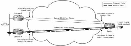
As you can see in Figure 7-47, all outbound and inbound traffic is now sent over the primary GRE/IPsec tunnel via London-1 in normal operation. If the London-1 gateway should fail, however, all traffic fails over to the GRE/IPsec tunnel via the London-2 gateway.
You might also notice in Example 7-60 that the Paris gateway is still load balancing traffic for the 10.1.1.0/24 and 10.12.12.0/24 networks across its two GRE tunnels (via London-1 and London-2). To ensure that all traffic in the IPsec VPN uses a primary path via the London-1 gateway, it would be necessary to modify the delay metric on the Paris and Milan gateways (as demonstrated on the Berlin gateway in Example 7-56). In addition, it would be necessary to modify the delay metric on the tunnel interfaces on the London-2 that connect to the Paris and Milan spoke site such that all inbound traffic to the Paris and Milan sites also goes via the London-1 gateway (as demonstrated for traffic inbound to the Berlin site in Example 7-59).
So, load balancing inbound and outbound traffic over tunnels from a particular spoke gateway is usually a bad idea, but it is still possible to load balance traffic to multiple hub site gateways, as illustrated in Figure 7-48.
Figure 7-48. Load Balancing to Hub Site Gateways
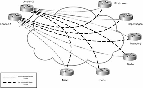
In Figure 7-48, the Stockholm, Copenhagen, and Hamburg gateways' primary GRE/IPsec tunnels terminate on the London-2 hub site gateway. Their backup GRE/IPsec tunnels terminate on the London-1 gateway.
The Berlin, Paris, and Milan gateways' primary GRE/IPsec tunnels terminate on the London-1 gateway, and their backup GRE/IPsec tunnels terminate on the London-2 gateway.
So, in normal operation for the IPsec VPN shown in Figure 7-48, traffic would be evenly load balanced between the London-1 and London-2 gateways. If one of the hub site gateways were to fail, all traffic would be transported via the remaining hub site gateway or gateways.
One advantage of using GRE/IPsec tunnels for high availability is that GRE/IPsec tunnels can be used to provide high availability where hub site gateways are co-located or when hub site gateways are located at geographically dispersed sites.
Figure 7-49 illustrates using GRE/IPsec tunnels for high availability when hub site gateways are geographically dispersed.
Figure 7-49. High Availability with GRE/IPsec Tunnels When Hub Site Gateways Are Geographically Dispersed
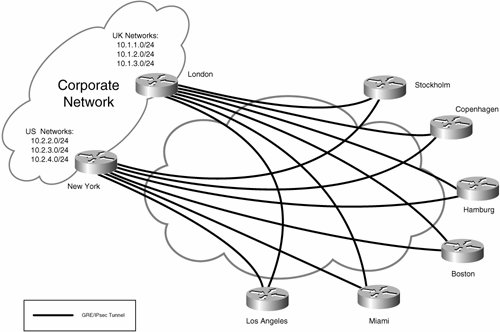
In Figure 7-49, all spoke site gateways are connected to the London and New York hub site gateways via GRE/IPsec tunnels.
In this case, it is usually unnecessary to configure the primary and backup GRE/IPsec tunnels by modifying routing protocol metrics, because traffic will naturally be routed over the tunnel that provides the shortest path to a particular destination (assuming you use a dynamic routing protocol).
For example, in Figure 7-49, traffic from the Los Angeles site destined for one of the U.S. networks (10.2.2.0/24, 10.2.3.0/24, and 10.2.4.0/24) would normally be routed over the GRE/IPsec tunnel via the New York hub site gateway (because of the shorter routing protocol path). If the New York gateway were to go down, however, traffic from the Los Angeles site destined for one of the U.S. networks would be routed via the London gateway (the longer routing protocol path).
High Availability with DMVPN
As you saw in the preceding section, point-to-point GRE/IPsec tunnels can work well as a solution for providing high availability in an IPsec VPN. But, as previously discussed, the use of point-to-point GRE/IPsec tunnels does not scale well (because of the amount of configuration required).
A more scalable solution for high availability with GRE/IPsec is to use DMVPN.
In this case, the hub site gateways are configured with multipoint GRE (mGRE) interfaces, and the spoke site gateways are configured with either point-to-point GRE or mGRE interfaces.
There are two ways to configure DMVPN for high availability:
- The gateways are connected over one DMVPN.
- The gateways are connected over two DMVPNs.
High Availability with Gateways Connected over One DMVPN
Figure 7-50 illustrates the configuration of DMVPN for high availability with all gateways connected over one network (DMVPN).
Figure 7-50. High Availability with One DMVPN
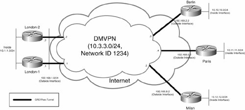
In Figure 7-50, the London-1, London-2, Berlin, Paris, and Milan sites are all connected over one DMVPN (network 10.3.3.0/24, NHRP network ID 1234).
Example 7-61 shows the configuration required on the London-1 and London-2 hub site gateways when using one DMVPN (IP network 10.3.3.0/24, and NHRP network ID 1234).
Example 7-61. Configuration of the London-1 and London-2 Hub site Gateways When Using One DMVPN
London-1#show running-config
Building configuration...
!
! London-1 gateway configuration
!
!
! IKE policy
!
crypto isakmp policy 10
 authentication pre-share
!
!
! Wildcard pre-shared key
!
crypto isakmp key mjlnet address 0.0.0.0 0.0.0.0
!
!
! IPsec transform set
!
crypto ipsec transform-set mjlnettrans esp-3des esp-sha-hmac
!
!
! IPsec profile
!
crypto ipsec profile mjlnetprofile
 set transform-set mjlnettrans
!
!
! mGRE tunnel interface
!
interface Tunnel0
 ip address 10.3.3.1 255.255.255.0 (line 1)
 no ip next-hop-self eigrp 100
 ip nhrp authentication mjlnet
 ip nhrp map multicast dynamic
 ip nhrp map 10.3.3.2 192.168.1.2
 ip nhrp map multicast 192.168.1.2
 ip nhrp network-id 1234
 ip nhrp nhs 10.3.3.2
 no ip split-horizon eigrp 100
 tunnel source 192.168.1.1
 tunnel mode gre multipoint
 tunnel key 5678
 tunnel protection ipsec profile mjlnetprofile
!
!
! Inside interface
!
interface FastEthernet0/0
 ip address 10.1.1.1 255.255.255.0
!
!
! Outside interface
!
interface Serial1/0
 ip address 192.168.1.1 255.255.255.0
!
!
! EIGRP for site-to-site reachability (line 2)
!
router eigrp 100
 passive-interface Ethernet3/0
 network 10.1.1.0 0.0.0.255
 network 10.3.3.0 0.0.0.255
 no auto-summary
!
London-2#show running-config Building configuration... ! ! London-2 gateway configuration ! ! ! IKE policy ! crypto isakmp policy 10 authentication pre-share ! ! ! Wildcard pre-shared key ! crypto isakmp key mjlnet address 0.0.0.0 0.0.0.0 ! ! ! IPsec transform set ! crypto ipsec transform-set mjlnettrans esp-3des esp-sha-hmac ! ! ! IPsec profile ! crypto ipsec profile mjlnetprofile set transform-set mjlnettrans ! ! ! mGRE tunnel interface ! interface Tunnel0 ip address 10.3.3.2 255.255.255.0 (line 3) no ip next-hop-self eigrp 100 ip nhrp authentication mjlnet ip nhrp map multicast dynamic ip nhrp map 10.3.3.1 192.168.1.1 ip nhrp map multicast 192.168.1.1 ip nhrp network-id 1234 ip nhrp nhs 10.3.3.1 no ip split-horizon eigrp 100 delay 50001 (line 4) tunnel source 192.168.1.2 tunnel mode gre multipoint tunnel key 5678 tunnel protection ipsec profile mjlnetprofile ! ! ! Inside interface ! interface FastEthernet0/0 ip address 10.1.1.10 255.255.255.0 ! ! ! Outside interface ! interface Serial2/0 ip address 192.168.1.2 255.255.255.0 ! ! ! EIGRP for site-to-site reachability (line 5) ! router eigrp 100 network 10.1.1.0 0.0.0.255 network 10.3.3.0 0.0.0.255 no auto-summary ! |
Most of the configuration of the London-1 and London-2 gateways shown in Example 7-61 should be pretty familiar. If you are unsure as to basic DMVPN configuration, see the section "Dynamic Multipoint Virtual Private Network (DMVPN)" earlier in this chapter. Notice that only one tunnel interface is required on London-1 and London-2 (irrespective of the number of spoke sites).
Of particular significance is the fact that the London-1 and London-2 gateways are configured as NHSs for the DMVPN. If either London-1 or London-2 should fail, spoke gateways will simply use the remaining hub site gateway/NHS to access resources at the London site and to resolve the addresses of other spoke gateways.
Notice in highlighted lines 1 and 3 that the London-1 and London-2 hub site gateways are on the same DMVPN (network 10.3.3.0/24).
EIGRP is configured on London-1 and London-2 below highlighted lines 2 and 5. EIGRP provides IP reachability between all the sites in the DMVPN. Note that EIGRP is used for illustrative purposes only, and any routing protocol could be used for site-to-site reachability.
One other important command to note is the delay command configured on the mGRE tunnel interface on London-2 (see highlighted line 4). This command ensures that the path via the London-1 gateway is preferred for all traffic outbound from the London site to the spoke sites. The path via the London-1 gateway is preferred because the delay on the London-2 gateway is higher (50001 > 50000 [the default delay on London-1's GRE interface]), and so the composite EIGRP metric via the London-1 gateway is lower. Should the London-1 gateway go down, however, all traffic outbound to the spoke sites would simply fail over to the London-2 gateway.
Note that if you use OSPF as you routing protocol for site-to-site reachability, you can use the ip ospf cost interface configuration mode command to ensure that one of the hub site gateways is preferred over the other for outbound traffic to spoke sites (by configuring a lower OSPF cost on the preferred hub site gateway's tunnel interface).
Another important thing to notice in the configuration of London-1 and London-2 is the inclusion of the ip nhrp map, ip nhrp map multicast, and ip nhrp nhs commands on their mGRE tunnel interfaces. These commands are used to configure London-1 as a client of London-2, and London-2 as a client of London-1this will ensure that there is direct connectivity between London-1 and London-2, and that the routing protocol will function correctly.
Now on to the configuration of the spoke gateways. Example 7-62 shows the configuration of the Berlin gateway with one DMVPN.
Example 7-62. Configuration of the Berlin Spoke Gateway with One DMVPN
Berlin#show running-config Building configuration... ! ! Berlin gateway configuration ! ! ! IKE policy ! crypto isakmp policy 10 authentication pre-share ! ! ! Wildcard pre-shared key ! crypto isakmp key mjlnet 0.0.0.0 0.0.0.0 ! ! ! IPsec transform set ! crypto ipsec transform-set mjlnettrans esp-3des esp-sha-hmac ! ! ! IPsec profile ! crypto ipsec profile mjlnetprofile set transform-set mjlnettrans ! ! ! mGRE tunnel interface ! interface Tunnel0 ip address 10.3.3.3 255.255.255.0 ip nhrp authentication mjlnet ip nhrp map 10.3.3.1 192.168.1.1 (line 1) ip nhrp map multicast 192.168.1.1 (line 2) ip nhrp map multicast 192.168.1.2 (line 3) ip nhrp map 10.3.3.2 192.168.1.2 (line 4) ip nhrp network-id 1234 ip nhrp nhs 10.3.3.1 (line 5) ip nhrp nhs 10.3.3.2 (line 6) tunnel source 192.168.2.2 tunnel mode gre multipoint tunnel key 5678 tunnel protection ipsec profile mjlnetprofile ! ! ! Inside interface ! interface FastEthernet2/0 ip address 10.10.10.1 255.255.255.0 ! ! ! Outside interface ! interface FastEthernet2/0 ip address 192.168.2.2 255.255.255.0 ! ! ! EIGRP for site-to-site reachability ! router eigrp 100 network 10.2.2.0 0.0.0.255 network 10.3.3.0 0.0.0.255 distance 95 10.3.3.2 0.0.0.0 10 (line 7) no auto-summary ! ! access-list 10 permit any (line 8) ! ! |
Once again, much of the configuration of the Berlin spoke gateway is standard DMVPN configuration. As shown in highlighted lines 1 through 6, however, the ip nhrp map, ip nhrp map multicast, and ip nhrp nhs commands are duplicated. These three commands are used to configure the NHS on the Berlin gateway, and because there are two NHSs in this example (London-1 [192.168.1.1/10.3.3.1] and London-2 [192.168.1.2/10.3.3.2]), the configuration is duplicated.
Also, take a look at highlighted line 7the distance admin-distance ip-address wildcard-mask access-list command here is used to apply an administrative distance of 95 to any routes (as specified by access list 10 in highlighted line 8) received from hub site gateway 10.3.3.2 (London-2). Because the default administrative distance for (internal) EIGRP routes is 90, this means that routes received from hub site gateway 10.3.3.1 (London-1) will be preferred over routes received from 10.3.3.2 (London-2), and so traffic outbound from the Berlin spoke gateway to the London site will traverse the London-1 hub site gateway.
It is worth noting that the delay command cannot be used on the GRE interface on the Berlin gateway (as it was in the previous section) to ensure that outbound traffic takes the path via the London-1 gateway because the interface here is multipoint, and so any delay that was configured would affect all paths via the interface (to all gateways [London-1 and London-2]).
Remember that the delay command applied to the tunnel interface on London-2 (see highlighted line 4, Example 7-61) causes traffic inbound from the London site to the Berlin site also to traverse the London-1 gateway. So, the delay command on London-2 and the distance command on the Berlin gateway cause inbound and outbound traffic to traverse the London-1 gateway, giving symmetric routing.
Note that the distance command can also be used if you use OSPF as your routing protocol for site-to-site reachability. In this case, you can specify an administrative distance greater than 110 (the default administrative distance for OSPF routes) for OSPF routes received from the backup hub site gateway so that routes received from the primary hub site gateway will be preferred.
So, for example, the distance 112 10.3.3.2 0.0.0.0 10 command (configured on spoke site gateways in OSPF router configuration mode) would ensure that all routes (specified by access list 10) received from the London-2 gateway (10.3.3.2) were given an administrative distance of 112, and that routes received from the London-1 gateway (with a default administrative distance of 110) would therefore be preferred for outbound traffic.
Figure 7-51 illustrates the traffic flow when the delay of 50001 is configured on London-2 (see highlighted line 4, Example 7-61), and the distance command is configured on the Berlin gateway (see highlighted line 7, Example 7-62).
Figure 7-51. Symmetric Routing in the VPN with One DMVPN
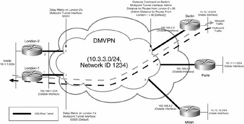
Figure 7-51 shows that in normal operation, all traffic inbound to and outbound from the Berlin site flows via the London-1 gateway.
High Availability with Gateways Connected over Two DMVPNs
Another way of provisioning high availability with DMVPN is to configure two DMVPNs, one connected to each hub site gateway, as illustrated in Figure 7-52.
Figure 7-52. High Availability with Two DMVPNs
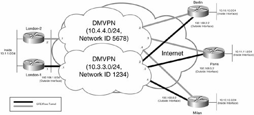
As you can see in Figure 7-52, each of the spoke gateways (Berlin, Paris, and Milan) are connected to two DMVPNs, one with London-1 as its NHS (IP network 10.3.3.0/24, and NHRP network ID 1234) and one with London-2 as its NHS (IP network 10.4.4.0/24, and NHRP network ID 5678).
The advantage of using two DMVPNs is that control of user traffic is easier than when using a single DMVPN for high availability.
Example 7-63 shows the configuration of the London-1 and London-2 hub site gateways when using two DMVPNs.
Example 7-63. Configuration of the London-1 and London-2 Hub site Gateways When Using Two DMVPNs
London-1#show running-config
Building configuration...
!
! London-1 gateway configuration
!
!
! IKE policy
!
crypto isakmp policy 10
 authentication pre-share
!
!
! Wildcard pre-shared key
!
crypto isakmp key mjlnet address 0.0.0.0 0.0.0.0
!
!
! IPsec transform set
!
crypto ipsec transform-set mjlnettrans esp-3des esp-sha-hmac
!
!
! IPsec profile
!
crypto ipsec profile mjlnetprofile
 set transform-set mjlnettrans
!
!
! mGRE tunnel interface
!
interface Tunnel0
 ip address 10.3.3.1 255.255.255.0 (line 1)
 no ip next-hop-self eigrp 100
 ip nhrp authentication mjlnet
 ip nhrp map multicast dynamic
 ip nhrp network-id 1234 (line 2)
 no ip split-horizon eigrp 100
 tunnel source 192.168.1.1
 tunnel mode gre multipoint
 tunnel key 5678
 tunnel protection ipsec profile mjlnetprofile
!
!
! Inside interface
!
interface FastEthernet0/0
 ip address 10.1.1.1 255.255.255.0
!
!
! Outside interface
!
interface Serial1/0
 ip address 192.168.1.1 255.255.255.0
!
!
! EIGRP for site-to-site reachability
!
router eigrp 100
 passive-interface Ethernet3/0
 network 10.1.1.0 0.0.0.255
 network 10.3.3.0 0.0.0.255
 no auto-summary
!
!
! End
London-2#show running-config Building configuration... ! ! London-2 gateway configuration ! ! ! IKE policy ! crypto isakmp policy 10 authentication pre-share ! ! ! Wildcard pre-shared key ! crypto isakmp key mjlnet address 0.0.0.0 0.0.0.0 ! ! ! IPsec transform set ! crypto ipsec transform-set mjlnettrans esp-3des esp-sha-hmac ! ! ! IPsec profile ! crypto ipsec profile mjlnetprofile set transform-set mjlnettrans ! ! ! mGRE tunnel interface ! interface Tunnel0 ip address 10.4.4.1 255.255.255.0 (line 3) no ip next-hop-self eigrp 100 ip nhrp authentication mjlnet ip nhrp map multicast dynamic ip nhrp network-id 5678 (line 4) no ip split-horizon eigrp 100 delay 50001 (line 5) tunnel source 192.168.1.2 tunnel mode gre multipoint tunnel key 1234 tunnel protection ipsec profile mjlnetprofile ! ! ! Inside interface ! interface FastEthernet0/0 ip address 10.1.1.10 255.255.255.0 ! ! ! Outside interface ! interface Serial2/0 ip address 192.168.1.2 255.255.255.0 ! ! ! EIGRP for site-to-site reachability ! router eigrp 100 network 10.1.1.0 0.0.0.255 network 10.4.4.0 0.0.0.255 no auto-summary ! ! ! end |
The configuration of the London-1 and London-2 hub site gateways is much the same as that shown in Example 7-61. If you look at highlighted lines 1 to 4, however, you will see that London-1 and London-2 are now connected to separate DMVPNs. London-1 is connected to the DMVPN with network ID 1234, and using IP network 10.3.3.0/24. London-2, on the other hand, is connected to the DMVPN with network ID 5678, and using IP network 10.4.4.0/24.
Highlighted line 5 shows the delay 50001 command, which configures a delay of 50001 on the tunnel 0 interface of the London-2 gateway and causes traffic outbound from the London site to follow the path via the London-1 gateway (50001 > 50000 [the default delay on the tunnel 0 interface on London-1]).
Example 7-64 shows the configuration of spoke gateway Berlin with two DMVPNs.
Example 7-64. Configuration of the Berlin Spoke Gateway with Two DMVPNs
Berlin#show running-config Building configuration... ! ! Berlin gateway configuration ! ! ! IKE policy ! crypto isakmp policy 10 authentication pre-share ! ! ! Wildcard pre-shared key ! crypto isakmp key mjlnet address 0.0.0.0 0.0.0.0 ! ! ! IPsec transform set ! crypto ipsec transform-set mjlnettrans esp-3des esp-sha-hmac ! ! ! IPsec profile ! crypto ipsec profile mjlnetprofile set transform-set mjlnettrans ! ! ! mGRE tunnel interface for DMVPN with network id 1234/IP network 10.3.3.0/24 ! interface Tunnel0 (line 1) ip address 10.3.3.2 255.255.255.0 ip nhrp authentication mjlnet ip nhrp map 10.3.3.1 192.168.1.1 ip nhrp map multicast 192.168.1.1 ip nhrp network-id 1234 ip nhrp nhs 10.3.3.1 tunnel source Loopback100 (line 2) tunnel mode gre multipoint tunnel key 5678 tunnel protection ipsec profile mjlnetprofile ! ! ! mGRE tunnel interface for DMVPN with network id 5678/IP network 10.4.4.0/24 ! interface Tunnel1 (line 3) ip address 10.4.4.2 255.255.255.0 ip nhrp authentication mjlnet ip nhrp map 10.4.4.1 192.168.1.2 ip nhrp map multicast 192.168.1.2 ip nhrp network-id 5678 ip nhrp nhs 10.4.4.1 delay 50001 (line 4) tunnel source Loopback101 (line 5) tunnel mode gre multipoint tunnel key 1234 tunnel protection ipsec profile mjlnetprofile ! ! ! Loopback interface 100 for use as interface tunnel 0 source address ! interface Loopback100 (line 6) ip address 192.168.6.1 255.255.255.255 ! ! ! Loopback interface 101 for use as interface tunnel 1 source address ! interface Loopback101 (line 7) ip address 192.168.6.2 255.255.255.255 ! ! ! Inside interface ! interface FastEthernet1/0 ip address 10.10.10.1 255.255.255.0 ! ! ! Outside interface ! interface FastEthernet2/0 ip address 192.168.2.2 255.255.255.0 ! ! ! EIGRP for site-to-site reachability ! router eigrp 100 passive-interface FastEthernet1/0 network 10.2.2.0 0.0.0.255 network 10.3.3.0 0.0.0.255 network 10.4.4.0 0.0.0.255 no auto-summary ! ! ! end |
Notice in highlighted lines 1 and 3 the configuration of tunnel interfaces 0 and 1. Tunnel interface 0 connects to the DMVPN with network ID 1234 and IP network 10.3.3.0/24, and tunnel interface 1 connects to the DMVPN with network id 5678 and IP network 10.4.4.0/24.
Also notice that the tunnel source address for tunnel interfaces 0 and 1 correspond to loopback interfaces 100 and 101, respectively (see highlighted lines 2, 5, 6, and 7). When using two DMVPNs, you must use separate tunnel source addresses with each tunnel interface; otherwise, your DMVPNs will not function correctly. And, make sure that the tunnel source addresses (here, those configured on loopback interfaces 100 and 101) are globally reachable (they can be reached from the other gateways in the DMVPN).
In highlighted line 4 you can see the delay 50001 command configured on tunnel interface 1. I am sure you can guess the function of this command, but to reiterate, its function is to ensure that traffic outbound from the Berlin site uses the tunnel 0 interface via London-1 gateway (the DMVPN with network ID 1234 and IP network 10.3.3.0/24). Outbound traffic uses the path via the London-1 gateway because the tunnel 0 interface (to London-1) has a lower delay than the tunnel 1 interface (50000 < 50001).
Figure 7-53 illustrates the traffic flow outbound from and inbound to the Berlin site with two DMVPNs.
Figure 7-53. Traffic Flow with Two DMVPNs
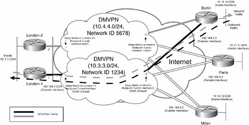
As illustrated in Figure 7-53, all traffic outbound from and inbound to the Berlin site flows via the London-1 gateway in normal operation. In the event that London-1 fails, user traffic will fail over to the London-2 gateway.
Designing QoS for IPsec VPNs |
Part I: Understanding VPN Technology
What Is a Virtual Private Network?
- What Is a Virtual Private Network?
- VPN Devices
- Deploying Site-to-Site and Remote Access VPNs: A Comparison
- Summary
- Review Questions
Part II: Site-to-Site VPNs
Designing and Deploying L2TPv3-Based Layer 2 VPNs
- Designing and Deploying L2TPv3-Based Layer 2 VPNs
- Benefits and Drawbacks of L2TPv3-Based L2VPNs
- L2TPv3 Pseudowire Operation
- Configuring and Verifying L2TPv3 Pseudowires
- Summary
- Review Questions
Designing and Implementing AToM-Based Layer 2 VPNs
- Designing and Implementing AToM-Based Layer 2 VPNs
- Benefits and Drawbacks of AToM-Based L2VPNs
- AToM Pseudowire Operation
- Deploying AToM Pseudowires
- Implementing Advanced AToM Features
- Summary
- Review Questions
Designing MPLS Layer 3 Site-to-Site VPNs
- Designing MPLS Layer 3 Site-to-Site VPNs
- Advantages and Disadvantages of MPLS Layer 3 VPNs
- MPLS Layer 3 VPNs Overview
- A Detailed Examination of MPLS Layer 3 VPNs
- Deploying MPLS Layer 3 VPNs
- Summary
- Review Questions
Advanced MPLS Layer 3 VPN Deployment Considerations
- Advanced MPLS Layer 3 VPN Deployment Considerations
- The Carriers Carrier Architecture
- The Inter-Autonomous System/Interprovider MPLS VPN Architecture
- Supporting Multicast Transport in MPLS Layer 3 VPNs
- Implementing QoS for MPLS Layer 3 VPNs
- Supporting IPv6 Traffic Transport in MPLS Layer 3 VPNs Using 6VPE
- Summary
- Review Questions
Deploying Site-to-Site IPsec VPNs
- Deploying Site-to-Site IPsec VPNs
- Advantages and Disadvantages of IPsec Site-to-Site VPNs
- IPsec: A Security Architecture for IP
- Deploying IPsec VPNs: Fundamental Considerations
- Summary
- Review Questions
Scaling and Optimizing IPsec VPNs
- Scaling and Optimizing IPsec VPNs
- Scaling IPsec Virtual Private Networks
- Ensuring High Availability in an IPsec VPN
- Designing QoS for IPsec VPNs
- MTU and Fragmentation Considerations in an IPsec VPN
- Summary
- Review Questions
Part III: Remote Access VPNs
Designing and Implementing L2TPv2 and L2TPv3 Remote Access VPNs
- Designing and Implementing L2TPv2 and L2TPv3 Remote Access VPNs
- Benefits and Drawbacks of L2TP Remote Access VPNs
- Operation of L2TP Voluntary/Client-Initiated Tunnel Mode
- Implementing L2TP Voluntary/Client-Initiated Tunnel Mode Remote Access VPNs
- Designing and Implementing L2TP Compulsory/NAS-Initiated Tunnel Mode Remote Access VPNs
- Integrating L2TP Remote Access VPNs with MPLS VPNs
- Summary
- Review Questions
Designing and Deploying IPsec Remote Access and Teleworker VPNs
- Designing and Deploying IPsec Remote Access and Teleworker VPNs
- Comparing IPsec Remote Access VPNs with Other Types of Remote Access VPNs
- Understanding IKE in an IPsec Remote Access VPN Environment
- Deploying IPsec Remote Access VPNs Using Preshared Key and Digital Signature Authentication
- Summary
- Review Questions
Designing and Building SSL Remote Access VPNs (WebVPN)
- Designing and Building SSL Remote Access VPNs (WebVPN)
- Comparing SSL VPNs to Other Types of Remote Access VPNs
- Understanding the Operation of SSL Remote Access VPNs
- Using Clientless SSL Remote Access VPNs (WebVPN) on the Cisco VPN 3000 Concentrator
- Implementing Full Network Access Using the Cisco SSL VPN Client
- Strengthening SSL Remote Access VPNs Security by Implementing Cisco Secure Desktop
- Enabling SSL VPNs (WebVPN) on Cisco IOS Devices
- Deploying SSL VPNs (WebVPN) on the ASA 5500
- Summary
- Review Questions
Part IV: Appendixes
Designing and Building SSL Remote Access VPNs (WebVPN)
- Designing and Building SSL Remote Access VPNs (WebVPN)
- Appendix A. VPLS and IPLS Layer 2 VPNs
- Understanding VPLS
- Understanding IPLS
- Summary: Comparing VPLS and IPLS
Appendix B. Answers to Review Questions
EAN: 2147483647
Pages: 124
