Implementing QoS for MPLS Layer 3 VPNs
One element of MPLS Layer 3 VPN design and deployment that is becoming more and more important is quality of service (QoS). The deployment of QoS can allow an MPLS VPN backbone network to support the tight service level requirements for applications such as voice and video.
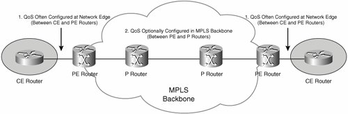
Two popular QoS deployment models used by MPLS VPN service providers are to
- Configure QoS mechanisms at the edge (between CE and PE routers) with no QoS configuration in the core (between PE and P routers).
- Configure QoS mechanisms both at the edge and in the core.
QoS is often configured at the edge because of the typical scarcity of bandwidth there. In the core, on the other hand, some service providers simply overprovision the amount of bandwidth such that even during failure scenarios, bandwidth is still plentiful and service levels can still be guaranteed even for applications such as voice and video. Other service providers consider that overprovisioning of bandwidth is too expensive and so deploy QoS configuration to ensure that they can still guarantee service levels with less core bandwidth.
Figure 5-40 illustrates the QoS deployment models for MPLS VPN service providers.
Figure 5-40. QoS Deployment Models for MPLS VPN Service Providers
Service provider backbone (core) QoS design can comprise two overall elements:
- QoS configuration to support transmission performance This ensures that traffic is appropriately prioritized during periods of network congestion (application traffic with tight service requirements is prioritized over other traffic during congestion). Application service requirements can consist of elements such as maximum packet loss, maximum delay, maximum jitter (variable delay), and minimum bandwidth.
- Configuration to ensure service availability This ensures that during (partial) network failure scenarios, the service provider can continue to guarantee service availability for critical applications.
To provide (adequate) transmission performance, a service provider can implement a Differentiated Service (DiffServ, RFC2475) architecture in their backbone network. In a DiffServ architecture, packets are marked using packet fields such as the type of service (ToS) byte, Differentiated Service (DS) field, or MPLS Experimental (EXP) bits. These packet markings then indicate to routers in the path what level and type of service (queuing, bandwidth, selective dropping, and so on) they should offer to the packets.
Figure 5-41 shows the ToS byte, DS field, and MPLS EXP bits. As shown in Figure 5-41, the three EXP bits form part of the MPLS shim header (also see Figure 3-37 on page 189).
Figure 5-41. ToS Byte, DS Field, and MPLS EXP Bits
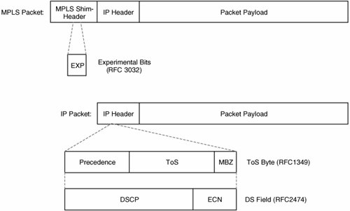
The fields of the ToS byte are defined in RFC1349 as follows:
- Precedence This 3-bit field defines the relative importance or priority of a packet.
- ToS This 4-bit field describes how the network should make tradeoffs between throughput, delay, reliability, and cost.
- MBZ This bit is unused and must be zero.
The use of the DS field has replaced that of the ToS byte in most networks. Its elements are described in RFCs 2474 and 3168 as follows:
- DSCP (Differentiated Service Code Point) This 6-bit field defines the Per-Hop Behavior (PHB), an externally observable forwarding behavior (QoS treatment) applied by a network device to packets marked with certain DSCP values. There are four DiffServ PHBs:
- Best Effort (BE)Indicated when all 6 bits of the DSCP field are zero. No specific QoS treatment is specified for this PHB (it is best effort!).
- Class Selector (CS)Used for backward compatibility with IP Precedence. When using the CS PHB, the last (least-significant) 3 bits of the DSCP field are zero.
- Assured Forwarding (AF, RFC 2597)Specifies four queuing classes and three drop thresholds (likelihoods of packets being dropped). When using AF, the first (most-significant) 3 bits of the DSCP field indicate the queuing class (which can be 1 to 4), and the next 2 bits indicate the drop threshold (which can be 1 to 3). AF PHB names are written in the format AFxy, where x is the queuing class, and y is the drop threshold.
- Expedited Forwarding (EF, RFC 3246)Specifies a single low-delay, -jitter, and-packet-loss QoS treatment with a certain bandwidth guarantee. This is typically used to ensure QoS for voice traffic.
- ECN (Explicit Congestion Notification) This 2-bit field defines a method by which network congestion can be communicated to hosts.
As described in RFC3270 (Multi-Protocol Label Switching (MPLS) Support of Differentiated Services), QoS markings can be indicated in two ways in an MPLS network:
- Based on the value carried in the MPLS shim header EXP bits In this case, the corresponding LSPs are referred to as EXP-Inferred Per-Hop-Behavior Scheduling Class LSPs (E-LSP).
- Based on the MPLS label value itself In this case, the corresponding LSPs are called Label-Only-Inferred Per-Hop-Behavior Scheduling Class LSPs (L-LSP). L-LSPs are, at present, only deployed in cell mode MPLS networks.
As previously mentioned, the backbone QoS design for service providers might also include mechanisms used to help ensure high service availability. MPLS traffic engineering (MPLS-TE), MPLS DiffServ-aware traffic engineering (MPLS DS-TE), and MPLS-TE fast reroute can be used to support service availability and transmission performance. MPLS-TE is beyond the scope of this book, but you can find more information in Traffic Engineering with MPLS (Cisco Press).
The sections that follow focus on the implementation of DiffServ QoS configuration in the MPLS backbone network.
MPLS DiffServ Tunneling Models
RFC3270 discusses two models for implementing DiffServ tunnelingthe Pipe Model and the Uniform Model. These two tunneling models allow integration or separation of customer and service provider DiffServ domains. A DiffServ domain is a set of network devices that apply a consistent set of QoS treatments based on a common set of PHBs.
Pipe Model/Short Pipe Model
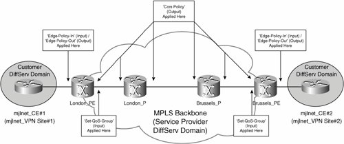
A Pipe Model architecture ensures that customer and service provider DiffServ domains are separate. Figure 5-42 shows an example of a Pipe Model architecture implemented in an MPLS backbone.
Figure 5-42. MPLS DiffServ Pipe Model Ensures That Customer and Service Provider DiffServ Domains Are Separate
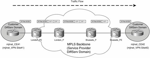
In Figure 5-42, the customer DiffServ domain comprises mjlnet_VPN sites 1 and 2; the service provider DiffServ domain comprises the devices in the MPLS backbone, including PE and P routers.
In the Pipe Model, when a customer packet arrives at ingress PE router London_PE from mjlnet_CE#1, the IP Precedence/DSCP marking in the IP header (in this example, IP Precedence 5/CS 5) is not copied to the MPLS EXP bits of the labels that are imposed on the packet (VPN and IGP labels). Instead, the PE router is configured to mark the MPLS EXP bits according to whatever QoS policy is configured in the service provider DiffServ domain, which in this example means that the packet is marked with MPLS EXP 3.
Next, London_PE forwards the packet to London_P, at which point, the MPLS EXP bits of the top (of stack) label are re-marked to 1 (this might be due to the amount of traffic arriving from London_PE exceeding a certain rate).
London_P then sends the packet to Brussels_P, which (being the penultimate hop) pops the IGP label, copies the MPLS EXP bit setting of the IGP label (1) to the VPN label, and forwards the packet Brussels_PE.
Finally, Brussels_PE removes the VPN label, and sends the unlabeled packet on to mjlnet_CE#2.
The key thing to notice here is that the IP Precedence/DSCP value of the unlabeled packet as it arrives at mjlnet_CE#2 (IP Precedence 5/CS5) is the same as that when the packet was sent from mjlnet_CE#1 to London_PE. So, irrespective of the marking (and any remarking of) MPLS EXP bit settings, the customer packet IP Precedence/DSCP value remains unchanged.
At this point, it is important to note that there are actually two varieties of Pipe Model architecturethe "standard" Pipe Model and the Short Pipe Model. The difference between these two models relates to the QoS forwarding treatment (queuing, shaping, and so on) on the egress interface of the egress PE router (the PE-CE interface). Figure 5-43 illustrates this difference.
Figure 5-43. Pipe Model and Short Pipe Model
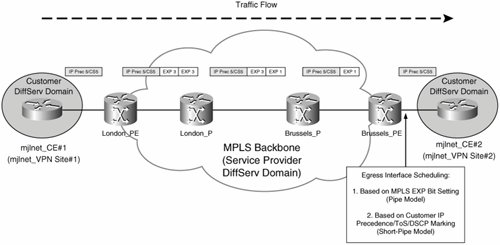
As shown in Figure 5-43, when using the Pipe Model, the QoS scheduling (queuing, shaping, and so on) on the egress interface (PE-CE interface) of the egress PE router is based on the MPLS EXP bit setting of the packetin Figure 5-43, this would mean that the egress interface QoS forwarding treatment was based on an MPLS EXP bit setting of 1.
When using, the Short Pipe Model, on the other hand, the egress interface QoS forwarding treatment is based on the customer IP packet's IP Precedence/DSCP value, which in Figure 5-43 is IP Precedence 5 (CS5).
Uniform Model
When using the Uniform Model, customer QoS markings are reflected in the MPLS EXP bit settings of the labels imposed on customer packet by the ingress PE router, and the MPLS EXP bit settings are reflected in the IP Precedence of the customer IP packets by the egress PE router.
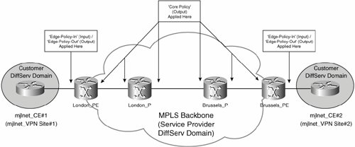
As illustrated in Figure 5-44, when using the Uniform Model, ingress PE router London_PE copies the IP Precedence of customer packets (5) to the MPLS EXP bits of the IGP and VPN labels that it imposes (MPLS EXP bit setting 5).
Figure 5-44. Uniform Model

London_PE now forwards the packet to London_P which, in this example, re-marks the MPLS EXP bit settings of the IGP label to a value of 1 (from a value of 5). London_P then sends the packet onward to Brussels_P.
Brussels_P pops the IGP label, copies the MPLS EXP bit setting of the IGP label (1) to the VPN label, and then forwards the packet to Brussels_PE.
Finally, Brussels_PE removes the VPN label and copies the MPLS EXP bit setting (1) to the IP Precedence field of the customer packet. Brussels_PE then sends the packet to mjlnet_CE#2.
So, the crucial difference between Uniform and Pipe models is the behavior of the ingress and egress PE routers.
When using the Pipe Model (or Short Pipe Model), the ingress PE router does not copy the IP Precedence of customer packets that it receives from its connected CE router to the MPLS EXP bit settings of labels that it imposes on the packets, and the egress PE router does not copy the MPLS EXP bit setting to the IP Precedence of customer packets that it transmits to its connected CE router.
When using the Uniform Model, on the other hand, the ingress PE router copies the IP Precedence of the customer packets that it receives from its connected CE router to the MPLS EXP bit settings of labels that it imposes, and the egress PE router copies the MPLS EXP bit settings to the IP Precedence field of customer packets that it transmits to its connected CE router.
Configuring MPLS QoS on Cisco Routers
Now that you understand the DiffServ tunneling models that can be implemented in an MPLS network, it is time to move on to configuration. This section describes the configuration of MPLS DiffServ Pipe Model, Short Pipe Model, and Uniform Model architectures.
Implementing an MPLS DiffServ Pipe Model Architecture
Implementation of an MPLS DiffServ Pipe Model architecture consists of the configuration of PE routers and P routers.
The configuration of PE routers comprises the following steps:
|
Step 1. |
Configure and apply an edge policy to apply in an input direction to the PE router's interface connected to CE routers. |
|
Step 2. |
Configure and apply a core policy to apply in an output direction to the PE router's core interfaces (connected to P or PE routers). |
Example 5-39 shows the configuration of a sample edge policy.
Example 5-39. Configuration of a Sample Edge Policy
! class-map match-any Edge-Control (line 1) match ip dscp cs6 class-map match-any Edge-Voice (line 2) match ip dscp ef class-map match-any Edge-Streaming-Video (line 3) match ip dscp af41 class-map match-any Edge-Priority-Apps (line 4) match ip dscp af21 af22 af23 af31 af32 af33 class-map match-any Edge-Other-Apps (line 5) match ip dscp af11 af12 af13 class-map match-any Edge-Default (line 6) match ip dscp default ! ! policy-map Edge-Policy-In (line 7) class Edge-Control (line 8) set mpls experimental imposition 3 class Edge-Voice (line 9) set mpls experimental imposition 5 class Edge-Streaming-Video (line 10) set mpls experimental imposition 4 class Edge-Priority-Apps (line 11) set mpls experimental imposition 3 class Edge-Other-Apps (line 12) set mpls experimental imposition 2 class Edge-Default (line 13) set mpls experimental imposition 2 ! ! interface Serial1/0 ip vrf forwarding mjlnet_VPN ip address 172.16.10.1 255.255.255.0 service-policy input Edge-Policy-In (line 14) ! |
In highlighted lines 1 to 6, six class maps are configured using the class-map [match-all | match-any] class-map-name command. The class maps are variously named Edge-Control, Edge-Voice, Edge-Streaming-Video, Edge-Priority-Apps, Edge-Other-Apps, and Edge-Default.
These class maps match traffic according to the DSCP setting in its IP header. So, for example, any traffic with a DSCP setting of Expedited Forwarding (EF) is matched by the Edge-Voice class map (highlighted line 2), and any traffic with a DSCP setting of Assured Forwarding 41 (AF41) is matched by the Edge-Streaming-Video class map (highlighted line 3).
Other class maps are used to match the following:
- Edge-Control This matches (transit) traffic marked with Class Selector (CS)/IP Precedence 6.
- Edge-Priority-Apps This matches traffic marked with DSCP code points AF21, AF22, AF23, AF31, AF32, and AF33.
- Edge-Other-Apps This matches packets with DSCP settings AF11, AF12, and AF13.
- Edge-Default This matches packets with DSCP setting default (000000).
Highlighted lines 7 to 13 show a policy map used to define QoS treatments for traffic matched by the class maps in highlighted lines 1 to 6.
The policy-map policy-map-name command (highlighted line 7) is used to configure a policy map called Edge-Policy-In that references the class maps using the class class-map-name command and defines QoS policy for traffic matched by the various class maps.
So, for example, the class Edge-Voice command (highlighted line 9) references the class map called Edge-Voice (highlighted line 2) and then sets the MPLS EXP bits for labels that are imposed on this traffic as it transmitted across the MPLS backbone to 5 using the set mpls experimental imposition mpls-exp-value command. There are three MPLS EXP bits, and so the valid bit settings (values) are 0 to 7.
Note
The set mpls experimental imposition command replaces the set mpls experimental command in Cisco IOS Software Release 12.2(13)T.
The policy map called Edge-Policy-In is also used to mark other packets as follows:
- Edge-Control (highlighted line 8) The policy map marks packets matched by this class map with MPLS EXP bit setting 3.
- Edge-Streaming-Video (highlighted line 10) Packets matched by this class map are marked with MPLS EXP bit setting 4.
- Edge-Priority-Apps (highlighted line 11) Packets matched by this class map are marked with MPLS EXP bit setting 3.
- Edge-Other-Apps (highlighted line 12) Packets matched by this class map are marked with MPLS EXP bit setting 2.
- Edge-Default (highlighted line 13) Packets matched by this class map are marked with MPLS EXP bit setting 2.
Having configured class maps and a policy map, the next step is to apply the policy map to the PE-CE interface.
The policy map called Edge-Policy-In is applied in an input direction on the PE-CE interface Serial 1/0 using the service-policy [input | output] policy-map-name command. This means that policy map Edge-Policy-In will be applied to any traffic received on the interface from the connected CE router.
It is worth noting that Edge-Policy-In simply classifies customer packets according to their DSCP markings (DSCP). This type of input PE-CE interface QoS policy is very trusting (DSCP values are trusted) and therefore would typically be seen if the service provider is also managing the CE routers. If the service provider is not managing the CE routers, more sophisticated classification and/or policing of customer traffic would typically be required on the PE router (based on IP addresses, TCP/UDP ports and so on). Some service providers also choose to police customer traffic received from CE routers, and then set the MPLS EXP bits for traffic according to whether the traffic has conformed to or exceeded a specified rate (using the police bps [burst-normal] [burst-max] conform-action set-mpls-experimental-imposition-transmit value exceed-action set-mpls-experimental-imposition-transmit value [violate-action action]).
So, QoS policy for traffic received by the ingress PE router on the PE-CE interface is now taken care of. But, it is also important to configure QoS policy on the PE router's PE-P router interface.
Example 5-40 shows the configuration of a sample QoS policy for PE-P interfaces.
Example 5-40. Configuration of a Sample QoS Policy for PE-P Interfaces
! class-map match-any Core-Control (line 1) match ip dscp cs6 match mpls experimental topmost 6 class-map match-any Core-Voice (line 2) match mpls experimental topmost 5 class-map match-any Core-Streaming-Video (line 3) match mpls experimental topmost 4 class-map match-any Core-Apps (line 4) match mpls experimental topmost 3 ! ! policy-map Core-Policy (line 5) class Core-Control (line 6) bandwidth percent 3 class Core-Voice (line 7) priority percent 25 class Core-Video (line 8) bandwidth percent 10 class Core-Apps (line 9) bandwidth percent 25 random-detect class class-default (line 10) bandwidth percent 37 random-detect ! interface FastEthernet2/0 ip address 10.10.10.1 255.255.255.0 max-reserved-bandwidth 100 (line 11) service-policy output Core-Policy (line 12) ! |
Highlighted lines 1 to 4 in Example 5-40 show the configuration of four class maps that explicitly match traffic with a variety of MPLS EXP bit settings as well as DSCP CS6.
For example, the Core-Voice class map (highlighted line 2) matches any traffic with MPLS EXP bit setting 5 in the topmost label in the label stack using the match mpls experimental topmost mpls-exp-value command. If you look back at Example 5-39 (highlighted line 9), you can see that the Edge-Policy-In policy map referenced class map Edge-Voice and set the MPLS EXP bits to 5 for customer traffic received on the PE-CE interface that matches this class map. So, class map Core-Voice will match labeled customer voice traffic.
Other class maps in Example 5-40 match traffic as follows:
- Core-Control (highlighted line 1) Matches packets with DSCP setting CS6 (IP Precedence 6) or MPLS EXP bit setting 6.
This class map matches control traffic such as BGP and LDP. Cisco routers mark control traffic using CS 6 (IP Precedence 6).
It is worth mentioning that Cisco routers ensure that (most types of) locally generated control traffic is not dropped (or dropped last) by using an internal mechanism called PAK_PRIORITY. PAK_PRIORITY is a flag that specifies the importance of packets as they are queued within a router.
You can find more information about PAK_PRIORITY at the following URL:
http://www.cisco.com/warp/public/105/rtgupdates.html
- Core-Streaming-Video (highlighted line 3) Matches labeled packets with MPLS EXP bit setting 4.
- Core-Apps (highlighted line 4) Matches labeled packets MPLS EXP bit setting 3.
In highlighted lines 5 to 10 in Example 5-40, you can see the configuration of a policy map called Core-Policy. The policy map references the class maps configured in highlighted lines 1 to 4 and configures queuing, assigns link bandwidth, and specifies congestion avoidance.
In the case of the Core-Voice class (highlighted line 7), the priority percent percentage command is used to configure Low Latency Queuing (LLQ). LLQ provides a priority queue for Class-Based Weighted Fair Queuing (CBWFQ), and this priority queue ensures that delay-sensitive traffic (such as voice) is transmitted before other types of traffic in other queues. In this example, the percent keyword is used to specify that 25 percent of link bandwidth is allocated to traffic in the priority queue during periods of congestion.
Policy map Core-Policy also specifies the following policies:
- Core-Control (highlighted line 6) This class map is referenced, and 3 percent of link bandwidth is assigned to this traffic type using the bandwidth percent percentage command.
- Core-Video (highlighted line 8) 10 percent of link bandwidth is assigned to traffic matched by this class map.
- Core-Apps (highlighted line 9) 25 percent of link bandwidth is assigned to traffic matched by this class map. Additionally, the random-detect command configures Weight Random Early Detection (WRED), a mechanism that provides congestion avoidance by selectively dropping packets during periods of congestion.
- class-default (highlighted line 10) 37 percent of link bandwidth is assigned and WRED is specified for this class.
In highlighted line 11 in Example 5-40, the max-reserved-bandwidth percent command configures the maximum bandwidth that can be reserved on interface FastEthernet 2/0 (a core interface connected to London_P) to 100 percent (the default is 75 percent).
Finally, the service-policy output policy-map-name command is used to apply the policy map called Core-Policy (configured in highlighted lines 5 to 10) to the interface. Note that because the policy map called Core-Policy assigns a total 100 percent of link bandwidth, it is essential to configure the max-reserved-bandwidth 100 command; otherwise, it is not possible to apply the policy to the interface.
So far, so good. The configuration in Example 5-39 classifies and marks customer traffic received by PE routers from the connected CE router. And, the configuration in Example 5-40 matches and specifies queuing treatment/bandwidth assignments/congestion avoidance for the (labeled) customer traffic as it is sent from the PE routers to P routers.
Now it is time to consider what QoS policy is required on the P routers. In fact, the configuration shown in Example 5-40 can also be applied to P router interfaces (again in an output direction). This configuration ensures consistent QoS treatment for customer traffic as it crosses the links between PE and P routers.
The only element of the Pipe Model architecture that remains is the configuration of the PE router to ensure that QoS treatment on PE-CE interfaces for packets sent to connected CE routers is based on MPLS EXP bit settings (rather than the underlying customer packet DSCP values/IP Precedence).
Example 5-41 and Example 5-42 provide a sample configuration (in two parts) to ensure that QoS treatment on PE-CE interfaces for packets sent to connected CE routers is based on MPLS EXP bit settings.
Example 5-41. Configuration of a Sample QoS Policy on the Egress PE Router (Part 1)
! class-map match-any EXP5 (line 1) match mpls experimental topmost 5 class-map match-any EXP4 (line 2) match mpls experimental topmost 4 class-map match-any EXP3 (line 3) match mpls experimental topmost 3 class-map match-any EXP2 (line 4) match mpls experimental topmost 2 ! ! policy-map Set-QoS-Group (line 5) class EXP5 (line 6) set qos-group 5 class EXP4 (line 7) set qos-group 4 class EXP3 (line 8) set qos-group 3 class EXP2 (line 9) set qos-group 2 ! interface FastEthernet2/0 ip address 10.10.10.1 255.255.255.0 service policy input Set-QoS-Group (line 10) ! |
The class maps in highlighted lines 1 to 4 (EXP1, EXP2, EXP3, and EXP4) match MPLS EXP bit settings 1 to 4.
The policy map configured in highlighted lines 5 to 9 (Set-QoS-Group) references the class maps configured in highlighted lines 1 to 4 and sets the QoS group value to the same value as the MPLS EXP bit setting (QoS group 5 is set for packets whose MPLS EXP bit setting is 5, and so on).
The QoS group is a Cisco router internal placeholder used here to temporarily store the MPLS EXP bit setting of packets that arrive at the PE router from P routers. This placeholder is necessary because the MPLS EXP bit settings are lost when MPLS labels are removed after the packets are received on the PE-P interfaceremember that the output QoS treatment on the PE-CE interface must correspond to the MPLS EXP bit setting in a Pipe Model architecture, so it is essential not to lose these values.
Finally, the policy map is applied in an input direction to the core interface (connected to a P router) in highlighted line 10.
Note
When you want every MPLS EXP bit setting to be written to a corresponding QoS group value (MPLS EXP 5 = QoS group 5, MPLS EXP 4 = Qos group 4, and so on) it is possible to achieve this more efficiently using the set qos-group mpls exp topmost command (under class class-default in a policy map).
Example 5-42 shows the second half of the configuration necessary to ensure the output QoS treatment on the PE-CE interface corresponds to the packets' MPLS EXP bit settings.
Example 5-42. Configuration of a Sample QoS Policy on the Egress PE Router (Part 2)
! class-map match-any QoSGroup5 (line 1) match qos-group 5 class-map match-any QoSGroup4 (line 2) match qos-group 4 class-map match-any QoSGroup3 (line 3) match qos-group 3 class-map match-any QoSGroup2 (line 4) match qos-group 2 ! ! policy-map Edge-Policy-Out (line 5) class QoSGroup5 (line 6) priority percent 25 class QoSGroup4 (line 7) bandwidth percent 10 class QoSGroup3 (line 8) bandwidth percent 25 random-detect class class-default (line 9) bandwidth percent 37 random-detect ! interface Serial1/0 ip vrf forwarding mjlnet_VPN ip address 172.16.10.1 255.255.255.0 max-reserved-bandwidth 100 (line 10) service-policy output Edge-Policy-Out (line 11) ! |
Highlighted lines 1 to 4 show the configuration of 4 class maps that match the QoS groups set by the Set-QoS-Group policy map configured previously in Example 5-41 (highlighted lines 5 to 9).
A policy map called Edge-Policy-Out is then configured in highlighted lines 5 to 9. This policy map references the class maps configured in highlighted lines 1 to 4 and specifies bandwidth assignments and congestion avoidance (WRED) for traffic corresponding to the various classes. So, for example, traffic with QoS group value 5 (MPLS EXP bit setting 5) is allocated 25 percent of link bandwidth, and traffic with QoS group 4 (MPLS EXP 4) is allocated 10 percent of link bandwidth.
The max-reserved-bandwidth 100 command is used to allow the reservation of 100 percent of link bandwidth, and the policy map is applied in an output direction to the PE-CE interface in highlighted lines 11 and 12, respectively.
The important concept to understand from the configuration in Examples 5-41 and 5-42 is how to preserve the MPLS EXP bit settings of packets using QoS groups. Notice that for the sake of simplicity (and focus on MPLS EXP to QoS group mapping), policy map Edge-Policy-Out uses exactly the same QoS treatments as specified in policy map Core-Policy back in Example 5-40. In certain cases (such as on slower Frame Relay access connections), the QoS treatment applied to packets sent by the PE router to a connected CE router might, for example, involve traffic shaping and/or link fragmentation and interleave (LFI).
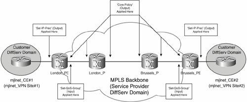
Figure 5-45 shows the application of the QoS policies shown in Examples 5-39 to 5-42 to PE and P routers.
Figure 5-45. Application of QoS Policies to PE and P Routers for Pipe Model Architecture
Note
More information on generic QoS configuration such as traffic shaping and LFI can be found in books such as IP Quality of Service (by Cisco Press).
Implementing an MPLS DiffServ Short Pipe Model Architecture
Now that you understand the configuration of a Pipe Model architecture, you'll find that the implementation of a Short Pipe Model architecture is pretty simple.
You will remember that the only difference between a Short Pipe Model architecture and a Pipe Model architecture is the output QoS treatment on the PE-CE interface of the PE routers (the QoS treatment is based on the IP Precedence/DSCP markings of the customer packets rather than the MPLS EXP bit settings [see Figure 5-43]).
The only difference from a configuration perspective, therefore, is that you do not need the Set-QoS-Group input policy (which preserves the MPLS EXP bit settings), and the Edge-Policy-Out policy map should be configured to match customer packet IP Precedence/DSCP markings rather QoS groups. Other QoS policies described in the previous section still apply.
Example 5-43 shows the configuration of Edge-Policy-Out so that it matches IP Precedence/DSCP markings of customer packets rather than QoS groups.
Example 5-43. Configuration of Edge-Policy-Out
! class-map match-any Edge-Control (line 1) match ip dscp cs6 class-map match-any Edge-Voice (line 2) match ip dscp ef class-map match-any Edge-Streaming-Video (line 3) match ip dscp af41 class-map match-any Edge-Priority-Apps (line 4) match ip dscp af21 af22 af23 af31 af32 af33 class-map match-any Edge-Other-Apps (line 5) match ip dscp af11 af12 af13 class-map match-any Edge-Default (line 6) match ip dscp default ! ! policy-map Edge-Policy-Out (line 7) class Edge-Control (line 8) priority percent 3 class Edge-Voice (line 9) bandwidth percent 25 class Edge-Streaming-Video (line 10) bandwidth percent 10 class Edge-Priority-Apps (line 11) bandwidth percent 15 random-detect dscp-based class Edge-Other-Apps (line 12) bandwidth percent 10 random-detect dscp-based class class-default (line 13) bandwidth percent 37 random-detect dscp-based ! interface Serial1/0 ip vrf forwarding mjlnet_VPN ip address 172.16.10.1 255.255.255.0 max-reserved-bandwidth 100 (line 14) service-policy output Edge-Policy-Out (line 15) ! |
Class maps matching customer packet IP Precedence/DSCP markings are shown in highlighted lines 1 to 6. You will notice that these class maps are actually the same as those shown in Example 5-39.
The Edge-Policy-Out policy map is then configured from highlighted line 7 to 13. The policy map references the class maps configured in highlighted lines 1 to 6, and specifies queuing, assigns bandwidths, and configures congestion avoidance (WRED).
Notice that the dscp-based keyword has been added to the random-detect command (which configures WRED) in this example. The effect of the dscp-based keyword is to allow WRED to take into account AF drop precedences when selectively dropping packets. So, packets with a drop precedence of 3 (AFx3) would be dropped earlier than packets within the same class with a drop precedence of 2 (AFx2), and packets with a drop precedence of 2 would be dropped earlier than packets within the same class with a drop precedence of 1 (AFx1).
Figure 5-46 shows the application of Short Pipe Model QoS policies to PE and P routers.
Figure 5-46. Application of Short Pipe Model QoS Policies to PE and P Routers
So, that is the Short Pipe Model. Now on to the Uniform Model.
Implementing an MPLS DiffServ Uniform Model Architecture
The configuration of a Uniform Model architecture differs from that of a Pipe or Short Pipe Model in the following ways:
- The IP Precedence/DSCP CS must be copied to the MPLS EXP bit setting at ingress PE routers.
- The MPLS EXP bit setting must be copied to the IP Precedence/DSCP CS at egress PE routers.
The copying of the IP Precedence/DSCP CS to the MPLS EXP bits on ingress PE routers is actually simple because this is the default behavior for Cisco routers (no explicit configuration is required).
Example 5-44 shows a sample configuration used to copy the MPLS EXP bit setting to the IP Precedence/DSCP CS field of customer packets on the (egress) PE router.
Example 5-44. Sample Configuration to Copy MPLS EXP Bit Setting to IP Precedence/DSCP CS Field of Customer Packets on the (Egress) PE Router
! policy-map Set-QoS-Group (line 1) class class-default (line 2) set qos-group mpls exp topmost ! policy-map Set-IP-Prec (line 3) class class-default (line 4) set precedence qos-group ! ! interface FastEthernet2/0 ip address 10.10.10.1 255.255.255.0 service policy input Set-QoS-Group (line 5) ! ! interface Serial1/0 ip vrf forwarding mjlnet_VPN ip address 172.16.10.1 255.255.255.0 service-policy output Set-IP-Prec (line 6) ! |
Highlighted lines 1 and 2 show the creation of a policy map called Set-QoS-Group. The purpose of this policy is to match all traffic and set the QoS group for each packet to the same value as the MPLS EXP bit setting of that packet (achieved using the set qos-group mpls exp topmost command). So, a packet that is received with MPLS EXP bit setting 5 will have its QoS group set to 5.
Another policy map called Set-IP-Prec is configured in highlighted lines 3 and 4. This policy again matches all traffic and sets the IP Precedence/DSCP CS of the packet to be the same as the corresponding QoS group (achieved using the set precedence qos-group command).
In highlighted lines 5 and 6, the Set-QoS-Group policy map is applied in an input direction to a core interface (connected to a P router), and the Set-IP-Prec policy map is applied in an output direction to a PE-CE interface (connected to a CE router).
The effect of the configuration in Example 5-44 is that the MPLS EXP of incoming labeled packets on the core interface is copied to QoS groups, and the QoS group values are then copied back to the IP Precedence of the corresponding unlabeled packets as they are transmitted on the PE-CE interface to the connected CE router.
Figure 5-47 shows the application of Uniform Model QoS policies to PE and P routers.
Figure 5-47. Application of Uniform Model QoS Policies to PE and P Routers
Part I: Understanding VPN Technology
What Is a Virtual Private Network?
- What Is a Virtual Private Network?
- VPN Devices
- Deploying Site-to-Site and Remote Access VPNs: A Comparison
- Summary
- Review Questions
Part II: Site-to-Site VPNs
Designing and Deploying L2TPv3-Based Layer 2 VPNs
- Designing and Deploying L2TPv3-Based Layer 2 VPNs
- Benefits and Drawbacks of L2TPv3-Based L2VPNs
- L2TPv3 Pseudowire Operation
- Configuring and Verifying L2TPv3 Pseudowires
- Summary
- Review Questions
Designing and Implementing AToM-Based Layer 2 VPNs
- Designing and Implementing AToM-Based Layer 2 VPNs
- Benefits and Drawbacks of AToM-Based L2VPNs
- AToM Pseudowire Operation
- Deploying AToM Pseudowires
- Implementing Advanced AToM Features
- Summary
- Review Questions
Designing MPLS Layer 3 Site-to-Site VPNs
- Designing MPLS Layer 3 Site-to-Site VPNs
- Advantages and Disadvantages of MPLS Layer 3 VPNs
- MPLS Layer 3 VPNs Overview
- A Detailed Examination of MPLS Layer 3 VPNs
- Deploying MPLS Layer 3 VPNs
- Summary
- Review Questions
Advanced MPLS Layer 3 VPN Deployment Considerations
- Advanced MPLS Layer 3 VPN Deployment Considerations
- The Carriers Carrier Architecture
- The Inter-Autonomous System/Interprovider MPLS VPN Architecture
- Supporting Multicast Transport in MPLS Layer 3 VPNs
- Implementing QoS for MPLS Layer 3 VPNs
- Supporting IPv6 Traffic Transport in MPLS Layer 3 VPNs Using 6VPE
- Summary
- Review Questions
Deploying Site-to-Site IPsec VPNs
- Deploying Site-to-Site IPsec VPNs
- Advantages and Disadvantages of IPsec Site-to-Site VPNs
- IPsec: A Security Architecture for IP
- Deploying IPsec VPNs: Fundamental Considerations
- Summary
- Review Questions
Scaling and Optimizing IPsec VPNs
- Scaling and Optimizing IPsec VPNs
- Scaling IPsec Virtual Private Networks
- Ensuring High Availability in an IPsec VPN
- Designing QoS for IPsec VPNs
- MTU and Fragmentation Considerations in an IPsec VPN
- Summary
- Review Questions
Part III: Remote Access VPNs
Designing and Implementing L2TPv2 and L2TPv3 Remote Access VPNs
- Designing and Implementing L2TPv2 and L2TPv3 Remote Access VPNs
- Benefits and Drawbacks of L2TP Remote Access VPNs
- Operation of L2TP Voluntary/Client-Initiated Tunnel Mode
- Implementing L2TP Voluntary/Client-Initiated Tunnel Mode Remote Access VPNs
- Designing and Implementing L2TP Compulsory/NAS-Initiated Tunnel Mode Remote Access VPNs
- Integrating L2TP Remote Access VPNs with MPLS VPNs
- Summary
- Review Questions
Designing and Deploying IPsec Remote Access and Teleworker VPNs
- Designing and Deploying IPsec Remote Access and Teleworker VPNs
- Comparing IPsec Remote Access VPNs with Other Types of Remote Access VPNs
- Understanding IKE in an IPsec Remote Access VPN Environment
- Deploying IPsec Remote Access VPNs Using Preshared Key and Digital Signature Authentication
- Summary
- Review Questions
Designing and Building SSL Remote Access VPNs (WebVPN)
- Designing and Building SSL Remote Access VPNs (WebVPN)
- Comparing SSL VPNs to Other Types of Remote Access VPNs
- Understanding the Operation of SSL Remote Access VPNs
- Using Clientless SSL Remote Access VPNs (WebVPN) on the Cisco VPN 3000 Concentrator
- Implementing Full Network Access Using the Cisco SSL VPN Client
- Strengthening SSL Remote Access VPNs Security by Implementing Cisco Secure Desktop
- Enabling SSL VPNs (WebVPN) on Cisco IOS Devices
- Deploying SSL VPNs (WebVPN) on the ASA 5500
- Summary
- Review Questions
Part IV: Appendixes
Designing and Building SSL Remote Access VPNs (WebVPN)
- Designing and Building SSL Remote Access VPNs (WebVPN)
- Appendix A. VPLS and IPLS Layer 2 VPNs
- Understanding VPLS
- Understanding IPLS
- Summary: Comparing VPLS and IPLS
Appendix B. Answers to Review Questions
EAN: 2147483647
Pages: 124
