Designing and Implementing L2TP Compulsory/NAS-Initiated Tunnel Mode Remote Access VPNs
Designing and Implementing L2TP Compulsory NAS Initiated Tunnel Mode Remote Access VPNs
As discussed at the beginning of this chapter, there are two modes of operation with L2TP: voluntary/client-initiated tunnel mode and compulsory/NAS-initiated tunnel mode. Up to this point in the chapter, the focus has been on voluntary tunnel mode; this section examines compulsory tunnel mode.
Figure 8-59 depicts compulsory tunnel mode L2TP.
Figure 8-59. Compulsory Tunnel Mode L2TP
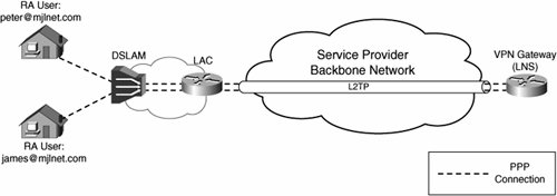
As shown in Figure 8-59, PPP connections (PPP over ATM [PPPoA] or PPP over Ethernet [PPPoE]) from users are transported via a DSL Access Multiplexor (DSLAM) and aggregation router over an L2TP tunnel to the a tunnel termination device (the VPN gateway). In Figure 8-59, the aggregation router functions as the LAC, and the tunnel termination device functions as the LNS. It is also possible that a DSLAM could function as a LAC.
Although Figure 8-59 shows the tunneling of PPP connections via a DSLAM and aggregation router (LAC) to an LNS, it does not really matter how PPP frames arrive at the LAC for tunneling to the LNSthey could arrive, for example, via analogue dialup lines, via ISDN lines, or they could as already discussed arrive via a DSLAM.
Figure 8-60 shows the operation of L2TP compulsory tunnel mode (when a remote access client initiates connectivity).
Figure 8-60. Operation of L2TP Compulsory Tunnel Mode
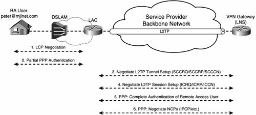
If you compare Figure 8-60 with Figure 8-6 on page 717, you can see that the operation of L2TP compulsory tunnel mode differs a little from the operation of L2TP voluntary tunnel mode.
As shown in Figure 8-60, when a remote access client connects to the LAC, the remote access client and the LAC negotiate LCP. In addition, partial PPP authentication is performed.
During partial PPP authentication, the LAC obtains the username of the remote access client and uses the username (or part of the username) to assign the PPP connection to the correct L2TP tunnel (there may be more than one).
At this point, if the L2TP tunnel has not already been established, the LAC will complete L2TP tunnel setup with the LNS. The LAC initiates L2TP tunnel setup by sending an SCCRQ message to the LNS (see Table 8-1 on page 716), the LNS replies with an SCCRP, and the LAC completes tunnel setup by sending an SCCCN.
After the L2TP tunnel has been established, the LAC and LNS will negotiate L2TP session setup. The LAC begins L2TP session establishment by sending an ICRP to the LNS. The LNS replies with an ICRP, and session setup is complete when the LAC sends an ICCN.
The LNS and the remote access client now complete PPP negotiation by completing PPP authentication and NCP negotiation. Note that it is also possible for the LNS to reinitiate LCP negotiation and authentication with the remote access client (rather than just completing the process).
L2TP Compulsory Tunnel Mode Setup: LAC Perspective
Example 8-19 shows L2TP compulsory tunnel mode setup from the LAC perspective.
Example 8-19. L2TP Compulsory Tunnel Mode Setup from the LAC Perspective
mjlnet.brux.lac#show debug PPP: PPP protocol negotiation debugging is on VPN: L2X protocol events debugging is on mjlnet.brux.lac# *Mar 1 00:19:07.236 UTC: BR0/0:1 PPP: Using dialer call direction *Mar 1 00:19:07.236 UTC: BR0/0:1 PPP: Treating connection as a callin *Mar 1 00:19:07.236 UTC: BR0/0:1 PPP: Phase is ESTABLISHING, Passive Open [0 sess, 0 load] (line 1) *Mar 1 00:19:07.236 UTC: BR0/0:1 LCP: State is Listen (line 2) *Mar 1 00:19:07.464 UTC: BR0/0:1 LCP: I CONFREQ [Listen] id 4 len 10 *Mar 1 00:19:07.464 UTC: BR0/0:1 LCP: MagicNumber 0x001DDF13 (0x0506001DDF13) *Mar 1 00:19:07.464 UTC: BR0/0:1 LCP: O CONFREQ [Listen] id 4 len 15 *Mar 1 00:19:07.464 UTC: BR0/0:1 LCP: AuthProto CHAP (0x0305C22305) *Mar 1 00:19:07.468 UTC: BR0/0:1 LCP: MagicNumber 0x0664DE58 (0x05060664DE58) *Mar 1 00:19:07.468 UTC: BR0/0:1 LCP: O CONFACK [Listen] id 4 len 10 *Mar 1 00:19:07.468 UTC: BR0/0:1 LCP: MagicNumber 0x001DDF13 (0x0506001DDF13) *Mar 1 00:19:07.480 UTC: BR0/0:1 LCP: I CONFACK [ACKsent] id 4 len 15 *Mar 1 00:19:07.480 UTC: BR0/0:1 LCP: AuthProto CHAP (0x0305C22305) *Mar 1 00:19:07.480 UTC: BR0/0:1 LCP: MagicNumber 0x0664DE58 (0x05060664DE58) *Mar 1 00:19:07.480 UTC: BR0/0:1 LCP: State is Open (line 3) *Mar 1 00:19:07.480 UTC: BR0/0:1 PPP: Phase is AUTHENTICATING, by this end [0 sess, 0 load] (line 4) *Mar 1 00:19:07.484 UTC: BR0/0:1 CHAP: O CHALLENGE id 4 len 32 from "mjlnet.brux.lac" (line 5) *Mar 1 00:19:07.504 UTC: BR0/0:1 CHAP: I RESPONSE id 4 len 41 from "joebloggs@mjlnet.com" (line 6) *Mar 1 00:19:07.504 UTC: BR0/0:1 PPP: Phase is FORWARDING [0 sess, 0 load] *Mar 1 00:19:07.516 UTC: Tnl 58518 L2TP: SM State idle *Mar 1 00:19:07.516 UTC: Tnl 58518 L2TP: O SCCRQ (line 7) *Mar 1 00:19:07.520 UTC: Tnl 58518 L2TP: Tunnel state change from idle to wait-ctl-reply *Mar 1 00:19:07.520 UTC: Tnl 58518 L2TP: SM State wait-ctl-reply *Mar 1 00:19:07.573 UTC: Tnl 58518 L2TP: I SCCRP from mjlnet.london.lns (line 8) *Mar 1 00:19:07.573 UTC: Tnl 58518 L2TP: Got a challenge from remote peer, mjlnet.london.lns *Mar 1 00:19:07.573 UTC: Tnl 58518 L2TP: Got a response from remote peer, mjlnet.london.lns *Mar 1 00:19:07.573 UTC: Tnl 58518 L2TP: Tunnel Authentication success *Mar 1 00:19:07.573 UTC: Tnl 58518 L2TP: Tunnel state change from wait-ctl-reply to established *Mar 1 00:19:07.573 UTC: Tnl 58518 L2TP: O SCCCN to mjlnet.london.lns tnlid 64727 (line 9) *Mar 1 00:19:07.577 UTC: Tnl 58518 L2TP: SM State established *Mar 1 00:19:07.581 UTC: Tnl/Cl 58518/3 L2TP: Session FS enabled *Mar 1 00:19:07.581 UTC: Tnl/Cl 58518/3 L2TP: Session state change from idle to wait-for-tunnel *Mar 1 00:19:07.581 UTC: BR0/0:1 Tnl/Cl 58518/3 L2TP: Create session *Mar 1 00:19:07.581 UTC: Tnl 58518 L2TP: SM State established *Mar 1 00:19:07.585 UTC: BR0/0:1 Tnl/Cl 58518/3 L2TP: O ICRQ to mjlnet.london.lns 64727/0 (line 10) *Mar 1 00:19:07.585 UTC: BR0/0:1 Tnl/Cl 58518/3 L2TP: Session state change from wait-for-tunnel to wait-reply *Mar 1 00:19:07.613 UTC: BR0/0:1 Tnl/Cl 58518/3 L2TP: O ICCN to mjlnet.london.lns 64727/3 (line 11) *Mar 1 00:19:07.613 UTC: BR0/0:1 Tnl/Cl 58518/3 L2TP: Session state change from wait-reply to established mjlnet.brux.lac# |
In highlighted lines 1 and 2, the PPP phase changes to ESTABLISHING, and LCP state changes to Listen. LCP negotiation is about to begin. The LCP state changes to Open in highlighted line 3LCP negotiation has been completed. Next, in highlighted line 4, the PPP phase changes to AUTHENTICATING(partial) PPP authentication is about to begin.
Highlighted line 5 and 6 show an outgoing CHAP challenge message (from the LAC to the remote access client) and an incoming CHAP Response message (from the remote access client to the LAC). You will notice, however, the absence of either a CHAP Success or Failure messagethese messages are used to complete CHAP authentication. So, CHAP authentication is partial between the LAC and the remote access client.
The remote access client's username is included in the CHAP Response message shown in highlighted line 6, and this is used by the LAC to associate this PPP connection with an L2TP tunnel to the LNS, mjlnet.London.LNS.01.
Because there is no existing L2TP tunnel between the LAC (mjlnet.brux.lac) and the LNS (mjlnet.london.lns), the LAC begins L2TP tunnel establishment by sending an SCCRQ to the LNS (highlighted line 7).
The LNS then replies with an SCCRP in highlighted line 8. In highlighted line 9, the LAC responds with an SCCCN, and the tunnel is established. The LAC now begins L2TP session establishment by sending an ICRQ (see highlighted line 10). The LNS replies to the ICRQ with an ICRP (not shown in the debug output), and finally, the LAC finishes L2TP session setup by sending an ICCN to the LNS (highlighted line 11).
L2TP Compulsory Tunnel Mode Setup: LNS Perspective
Example 8-20 shows L2TP tunnel setup and PPP negotiation from the LNS perspective.
Example 8-20. L2TP Compulsory Tunnel Mode Setup from the LNS Perspective
mjlnet.london.lns#show debug PPP: PPP protocol negotiation debugging is on VPN: L2X protocol events debugging is on mjlnet.london.lns# *Jun 20 17:38:20.839 UTC: L2TP: I SCCRQ from mjlnet.brux.lac tnl 58518 (line 1) *Jun 20 17:38:20.839 UTC: Tnl 64727 L2TP: Got a challenge in SCCRQ, mjlnet.brux.lac *Jun 20 17:38:20.839 UTC: Tnl 64727 L2TP: Tunnel Authorization started for host mjlnet.brux.lac *Jun 20 17:38:20.839 UTC: Tnl 64727 L2TP: New tunnel created for remote mjlnet.brux.lac, address 192.168.5.2 *Jun 20 17:38:20.839 UTC: L2X: Tunnel author reply found L2X info *Jun 20 17:38:20.839 UTC: Tnl 64727 L2TP: O SCCRP to mjlnet.brux.lac tnlid 58518 (line 2) *Jun 20 17:38:20.839 UTC: Tnl 64727 L2TP: Control channel retransmit delay set to 1 seconds *Jun 20 17:38:20.843 UTC: Tnl 64727 L2TP: Tunnel state change from idle to wait-ctl-reply *Jun 20 17:38:20.883 UTC: Tnl 64727 L2TP: I SCCCN from mjlnet.brux.lac tnl 58518 (line 3) *Jun 20 17:38:20.883 UTC: Tnl 64727 L2TP: Got a Challenge Response in SCCCN from mjlnet.brux.lac *Jun 20 17:38:20.883 UTC: Tnl 64727 L2TP: Tunnel Authentication success *Jun 20 17:38:20.883 UTC: Tnl 64727 L2TP: Tunnel state change from wait-ctl-reply to established *Jun 20 17:38:20.883 UTC: Tnl 64727 L2TP: SM State established *Jun 20 17:38:20.899 UTC: Tnl 64727 L2TP: I ICRQ from mjlnet.brux.lac tnl 58518 (line 4) *Jun 20 17:38:20.899 UTC: Tnl/Sn 64727/3 L2TP: Session state change from idle to wait-connect *Jun 20 17:38:20.899 UTC: Tnl/Sn 64727/3 L2TP: Accepted ICRQ, new session created *Jun 20 17:38:20.899 UTC: uid:2 Tnl/Sn 64727/3 L2TP: O ICRP to mjlnet.brux.lac 58518/3 (line 5) *Jun 20 17:38:20.899 UTC: Tnl 64727 L2TP: Control channel retransmit delay set to 1 seconds *Jun 20 17:38:20.939 UTC: uid:2 Tnl/Sn 64727/3 L2TP: I ICCN from mjlnet.brux.lac tnl 58518, cl 3 (line 6) *Jun 20 17:38:20.939 UTC: uid:2 Tnl/Sn 64727/3 L2TP: Session state change from wait-connect to wait-for-service-selection-iccn *Jun 20 17:38:20.939 UTC: ppp2 PPP: Phase is ESTABLISHING (line 7) *Jun 20 17:38:20.939 UTC: ppp2 LCP: I FORCED rcvd CONFACK len 11 (line 8) *Jun 20 17:38:20.939 UTC: ppp2 LCP: AuthProto CHAP (0x0305C22305) *Jun 20 17:38:20.939 UTC: ppp2 LCP: MagicNumber 0x0664DE58 (0x05060664DE58) *Jun 20 17:38:20.939 UTC: ppp2 LCP: I FORCED sent CONFACK len 6 (line 9) *Jun 20 17:38:20.939 UTC: ppp2 LCP: MagicNumber 0x001DDF13 (0x0506001DDF13) *Jun 20 17:38:20.939 UTC: ppp2 PPP: Phase is FORWARDING, Attempting Forward *Jun 20 17:38:20.939 UTC: ppp2 PPP: Phase is AUTHENTICATING, Unauthenticated User *Jun 20 17:38:20.939 UTC: ppp2 PPP: Phase is FORWARDING, Attempting Forward *Jun 20 17:38:20.943 UTC: Vi2.1 Tnl/Sn 64727/3 L2TP: Session state change from wait-for-service-selection-iccn to established *Jun 20 17:38:20.943 UTC: Vi2.1 PPP: Phase is AUTHENTICATING, Authenticated User (line 10) *Jun 20 17:38:20.943 UTC: Vi2.1 CHAP: O SUCCESS id 4 len 4 (line 11) *Jun 20 17:38:20.943 UTC: Vi2.1 PPP: Phase is UP *Jun 20 17:38:20.943 UTC: Vi2.1 PPP: Process pending ncp packets *Jun 20 17:38:20.947 UTC: Vi2.1 IPCP: O CONFREQ [Closed] id 1 len 10 (line 12) *Jun 20 17:38:20.947 UTC: Vi2.1 IPCP: Address 10.20.10.1 (0x03060A140A01) *Jun 20 17:38:20.979 UTC: Vi2.1 IPCP: I CONFREQ [REQsent] id 3 len 10 *Jun 20 17:38:20.979 UTC: Vi2.1 IPCP: Address 0.0.0.0 (0x030600000000) *Jun 20 17:38:20.979 UTC: Vi2.1 AAA/AUTHOR/IPCP: Start. Her address 0.0.0.0, we want 0.0.0.0 *Jun 20 17:38:20.979 UTC: Vi2.1 AAA/AUTHOR/IPCP: Done. Her address 0.0.0.0, we want 0.0.0.0 *Jun 20 17:38:20.979 UTC: Vi2.1 IPCP: Pool returned 10.30.10.50 *Jun 20 17:38:20.979 UTC: Vi2.1 IPCP: O CONFNAK [REQsent] id 3 len 10 *Jun 20 17:38:20.979 UTC: Vi2.1 IPCP: Address 10.30.10.50 (0x03060A1E0A32) *Jun 20 17:38:20.987 UTC: Vi2.1 IPCP: I CONFACK [REQsent] id 1 len 10 *Jun 20 17:38:20.987 UTC: Vi2.1 IPCP: Address 10.20.10.1 (0x03060A140A01) *Jun 20 17:38:21.003 UTC: Vi2.1 IPCP: I CONFREQ [ACKrcvd] id 4 len 10 *Jun 20 17:38:21.003 UTC: Vi2.1 IPCP: Address 10.30.10.50 (0x03060A1E0A32) *Jun 20 17:38:21.003 UTC: Vi2.1 IPCP: O CONFACK [ACKrcvd] id 4 len 10 *Jun 20 17:38:21.003 UTC: Vi2.1 IPCP: Address 10.30.10.50 (0x03060A1E0A32) *Jun 20 17:38:21.003 UTC: Vi2.1 IPCP: State is Open (line 13) *Jun 20 17:38:21.007 UTC: Vi2.1 IPCP: Install route to 10.30.10.50 *Jun 20 17:38:21.007 UTC: Vi2.1 IPCP: Add link info for cef entry 10.30.10.50 mjlnet.london.lns# |
Highlighted lines 1 to 3 show the exchange of SCCRQ, SCCRP, and SCCCN messages used to establish the L2TP tunnel between the LAC and the LNS.
In highlighted line 4 to 6, you can see the ICRQ, ICRP, and ICCN messages that set up the L2TP session.
Now that the L2TP session has been set up, the LNS can begin PPP negotiation with the remote access client (see highlighted line 7).
In highlighted line 8 and 9, the LNS processes LCP messages passed from the LAC during L2TP session setup (remember that the LAC negotiates LCP with the remote access client).
Highlighted line 10 shows that PPP authentication is about to begin, and in highlighted line 11, the LNS sends a CHAP Success message to the remote access client. The LAC also passed authentication information to the LAC during L2TP session setup, and so the LNS now only needs to send either a CHAP Success or Failure message to the remote access client depending on whether authentication was successful.
As soon as the LNS has authenticated the remote access client, it begins NCP (in this case IPCP) negotiation by sending an IPCP Configure-Request (CONFREQ, see highlighted line 12).
The IPCP state changes to Open in highlighted line 13, and IPCP negotiation is complete. The L2TP tunnel (and session) has been set up between the LAC and the LNS, and PPP negotiation has been completed between the LNS and the remote access client.
Configuring the LAC for Compulsory Tunnel Mode
The configuration of the LAC consists of the following steps:
|
Step 1. |
Configure access connectivity. |
|
Step 2. |
Configure AAA (optional). |
|
Step 3. |
Globally enable VPDNs. |
|
Step 4. |
Configure the VPDN groups. |
Example 8-21 shows a sample configuration of a LAC when using compulsory tunnel mode.
Example 8-21. Sample Configuration of a LAC When Using Compulsory Tunnel Mode
! hostname mjlnet.brux.lac ! vpdn enable (line 1) vpdn search-order domain (line 2) ! vpdn-group mjlnet.l2tp.vpn (line 3) request-dialin (line 4) protocol l2tp (line 5) domain mjlnet.com (line 6) initiate-to ip 192.168.5.1 (line 7) l2tp tunnel password 7 045802150C2E (line 8) ! ! interface FastEthernet0/0 (line 9) ip address 192.168.3.1 255.255.255.0 (line 10) ! controller E1 1/0 (line 11) pri-group timeslots 1-31 (line 12) ! interface Serial1/0:15 (line 13) no ip address (line 14) encapsulation ppp (line 15) isdn switch-type primary-net5 (line 16) isdn incoming-voice modem (line 17) no peer default ip address (line 18) ppp authentication chap (line 19) ! interface Group-Async1 (line 20) no ip address (line 21) encapsulation ppp (line 22) async mode interactive (line 23) no peer default ip address (line 24) ppp authentication chap (line 25) group-range 33 38 (line 26) ! line 33 38 (line 27) modem InOut (line 28) modem autoconfigure type mica (line 29) autoselect ppp (line 30) ! |
The vpdn enable command in line 1 enable VPDNs (including L2TP) on the LAC.
The vpdn search-order domain command (line 2) then configures the LAC to attempt to associate the remote access clients' PPP connections to an L2TP tunnel using the domain name contained in the username of the remote access client (specified by the remote user using the syntax username@domain_name, and communicated to the LAC during PPP authentication).
The next step is to configure the VPDN group (Step 3). Line 3 shows the vpdn-group name command, which configures the VPDN group name. A VPDN group is used to collect together the configuration for a particular VPN/VPDN. It is worth noting that the VPDN group name is locally significant on the LAC.
The first command configured under the VPDN group is (in this case) request-dialin (line 4). This command is used to configure the LAC to initiate L2TP tunnel/session establishment with the LNS on reception of PPP connections from remote access clients.
Next is the protocol l2tp command is used to configure L2TP as the tunneling protocol (line 5).
In line 6, the domain domain_name command is used to match the domain name in the username of the remote access user (username@domain_name).
Line 7 contains the initiate-to ip ip-address command. This command configures the IP address of the LNS (the L2TP tunnel endpoint).
The l2tp authentication password password command (line 8) is used to configure the L2TP tunnel password, which is used by the LAC to authenticate the LNS and vice versa (during tunnel setup).
Lines 9 and 10 show the configuration of the interface that provides connectivity to the LNS (via intervening networks).
In this example, the access connectivity to remote access clients is provided via a Primary Rate ISDN line (clients connect over the PRI to digital MICA modems in the LAC).
Lines 11 and 12 show the configuration of the E1 controller. The pri-groups timeslots timeslot-range command in line 12 specifies timeslots 1 to 31.
Lines 13 to 19 show the ISDN D channel configuration.
The encapsulation ppp command (line 15) is used, unsurprisingly, to configure PPP encapsulation on the line.
Line 16 shows the isdn switch-type switch-type, used to configure the ISDN switch type.
The isdn incoming-voice modem command (line 17) configures the LAC to switch asynchronous calls received on the PRI to the internal MICA modems.
The no peer default ip address command (line 18) ensures that the LAC does not assign an IP address to any remote access clients whose calls are received on the PRI. This command makes sense because IP addresses are assigned (if at all) during IPCP negotiation, and IPCP is not negotiated between the remote access clients and the LAC (it is instead negotiated between the remote access clients and the LNS).
Line 19 contains the ppp authentication chap command. This command configures the LAC to use CHAP authentication with the remote access clients.
Lines 20 to 26 show the configuration of the asynchronous interfaces. These interfaces are configured together in a group (thus ensuring consistency).
The encapsulation ppp command (line 21) again configures PPP encapsulation.
Line 22 shows the async mode interactive command. This configures allows users to initiate interactive mode on the lines.
The no peer default ip address command (line 23) again ensures that the LAC does not assign IP addresses to the remote access clients.
The group-range interface-range-start interface-range-finish command in line 24 then applies the configuration under interface Group-Async1 to the MICA modem lines.
In lines 25 to 28, you can see the configuration of the asynchronous lines.
The modem InOut command (line 26) ensures that the modems on the specified lines are able to both receive and make calls.
In line 27, the modem autoconfigure type mica command automatically configures the modems as type MICA.
Line 28 contains the autoselect ppp command ensures that the LAC can auto-detect PPP encapsulation on the modem lines.
Configuring Tunnel Definitions on a RADIUS Server
Although the configuration shown in Example 8-21 functions perfectly well, it is also common to store the VPDN/VPN configuration (configured under the VPDN group in Example 8-21) on a RADIUS server in the form of a tunnel definition.
There are two ways to configure tunnel definitions on a RADIUS server:
- Using IETF standard tunnel attributes. These attributes are described in RFC2868.
- Using Cisco AV pairs.
Table 8-2 shows the most relevant IETF standard tunnel attributes.
|
Attribute Type |
Attribute Name |
Description |
|---|---|---|
|
64 |
Tunnel-Type |
This attribute is used to specify the tunnel protocol. |
|
65 |
Tunnel-Medium-Type |
This describes the medium used to transport the tunnel. |
|
67 |
Tunnel-Server-Endpoint |
This is the IP address of the tunnel endpoint (the LNS). |
|
69 |
Tunnel-Password |
This attribute specifies the password used for tunnel authentication. |
|
82 |
Tunnel-Assignment-ID |
Identifies the tunnel to which a session is assigned. |
If you want to store tunnel configuration on a RADIUS server, you can remove the VPDN group configuration (no vpdn-group name) from the LAC and instead specify the commands shown in Example 8-22.
Example 8-22. AAA Configuration on the LAC
aaa new-model aaa authentication ppp default group radius aaa authorization network default group radius radius-server host 10.100.10.51 auth-port 1645 acct-port 1646 key cisco ! |
The aaa new-model command enables AAA on the LAC.
The aaa authentication ppp default group radius command is used to enable authentication for PPP using a RADIUS server (as specified using the default method list).
The aaa authorization network default group radius command configures the LAC to use a RADIUS server to authorize network connections. Again, the default method list is specified.
The radius server host command specifies the IP address or DNS name of the RADIUS server, the UDP ports used for authentication (auth-port) and accounting (acct-port) requests, and the key used to authenticate communications used between the LAC and the RADIUS server.
If you are using a Cisco Secure ACS, to get the tunnel definition to download correctly from the RADIUS server, you must complete the following steps:
|
Step 1. |
Configure a user account using the domain name as the username (for example, mjlnet.com). |
|
Step 2. |
Configure the password for the user account as cisco. This password is hard-coded on Cisco routers. |
|
Step 3. |
Configure a group, and within group settings configure the Service-Type attribute (attribute type 6) as outbound or dialout framed. |
|
Step 4. |
Ensure that No IP Assignment is configured under the user or group settings. |
|
Step 5. |
Configure IETF or Cisco AV-pair tunnel attributes under the group settings. |
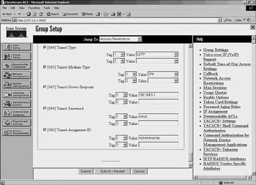
Figure 8-61 shows the configuration of IETF tunnel attributes on Cisco Secure ACS.
Figure 8-61. Configuration of IETF Tunnel Attributes on Cisco Secure ACS
Example 8-23 shows the equivalent configuration of IETF tunnel attributes on a Merit RADIUS server.
Example 8-23. Configuration of IETF Tunnel Attributes on a Merit RADIUS Server
mjlnet.com Password="cisco" Service-Type=Outbound Tunnel-Type = :1:L2TP Tunnel-Medium-Type = :1:IP Tunnel-Server-Endpoint = :1:192.168.5.1 Tunnel-Password = :1:"cisco" Tunnel-Assignment-ID = :1:"mjlnet.brux.lac" |
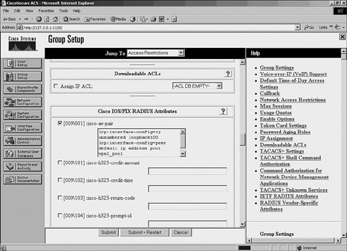
Figure 8-62 shows the configuration of Cisco AV-pairs on Cisco Secure ACS.
Figure 8-62. Configuration of Cisco AV-Pairs Tunnel Attributes on Cisco Secure ACS
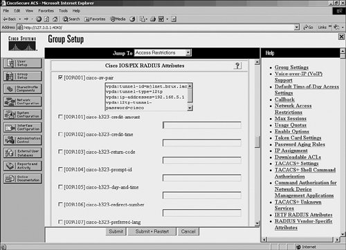
In Example 8-24, you can see the equivalent configuration of Cisco AV-pair tunnel attributes on a Merit RADIUS server.
Example 8-24. Configuration of Cisco AV-Pair Tunnel Attributes on a Merit RADIUS Server
mjlnet.com Password ="cisco" Service-Type=Outbound cisco-avpair = "vpdn:tunnel-id=mjlnet.brux.lac" cisco-avpair = "vpdn:tunnel-type=l2tp" cisco-avpair = "vpdn:ip-addresses=192.168.5.1" cisco-avpair = "vpdn:l2tp-tunnel-password=cisco" |
Configuring the LNS for Compulsory Tunnel Mode
When you have finished configuring the LAC, you can move on to configuring the LNS.
Configuration of the LNS consists of the following steps:
|
Step 1. |
Globally enable VPDNS. |
|
Step 2. |
Configure VPDN groups. |
|
Step 3. |
Configure virtual templates. |
|
Step 4. |
Configure IP address pools and other IP options. |
Example 8-25 shows a sample configuration of an LNS when using compulsory tunnel mode.
Example 8-25. Sample Configuration of an LNS When Using Compulsory Tunnel Mode
! hostname mjlnet.london.lac ! username mark@mjlnet.com password cisco (line 1) username john@mjlnet.com password disco (line 2) ! vpdn enable ! vpdn-group mjlnet.l2tp.vpn accept-dialin (line 3) protocol l2tp virtual-template 1 (line 4) terminate-from hostname mjlnet.brux.lac (line 5) l2tp tunnel password 7 01100F175804 ! async-bootp dns-server 10.50.10.55 (line 6) async-bootp nbns-server 10.50.10.56 (line 7) ! interface FastEthernet1/0 (line 8) ip address 192.168.5.1 255.255.255.0 (line 9) ! interface FastEthernet1/1 (line 10) ip address 10.50.10.1 255.255.255.0 (line 11) ! interface Virtual-Template1 (line 12) ip unnumbered FastEthernet1/1 (line 13) peer default ip address pool RA.Client.Addrs (line 14) ppp authentication chap (line 15) ! ip local pool RA.Client.Addrs 10.60.1.1 10.60.1.100 (line 16) ! |
Some of the commands configured on the LNS are the same as those configured on the LAC. These commands will not be reexamined heresee the descriptions of these commands earlier in this chapter for more information.
Lines 1 and 2 show the configuration of a local username/password database using the username username password password command. These usernames and passwords are used to authenticate remote access user during PPP negotiation.
The accept-dialin command (line 3) under the VPDN group is used to configure the LNS to accept L2TP tunnel and session setup initiated by the LAC. This command is the counterpart of the request-dialin command on the LAC.
Line 4 shows the virtual-template template-number command used to configure the virtual template from which virtual access interfaces will be cloned. These virtual access interfaces are used to terminate PPP connections that are tunneled from the remote access clients via the LAC to the LNS (one virtual access interface per PPP connection).
Next, the terminate-from hostname hostname command in line 5 is used to specify the hostname of the LAC from which L2TP tunnel and session setup will be accepted.
In lines 6 and 7, the async-bootp dns-server address and async-bootp nbns-server address commands are used to configure DNS server and NetBIOS Name Server (WINS server) addresses that are supplied to the remote access client during PPP (IPCP) negotiation.
Lines 8 and 9 show the configuration of the interface that provides connectivity (via intervening networks) to the LAC, and line 10 and 11 show the configuration an internal interface.
The virtual template interface is configured in lines 12 to 15. This is the virtual template referenced in the VPDN group using the virtual-template command (see line 4).
The ip unnumbered interface command (line 13) configures the virtual template to "borrow" the IP address from interface fast Ethernet 1/1.
Line 14 shows the peer default ip address pool pool-name command. This command is used to link to the pool of IP addresses from which an IP address will be assigned to the remote access clients during PPP (IPCP) negotiation.
Theppp authentication chap command (line 15) configures the LNS to use CHAP to authenticate remote access clients.
In line 16, the ip local pool pool-name command configures the IP address pool from which IP addresses are assigned to remote access clients. This is the pool referenced using the peer default ip address pool command in line 14.
The sample configuration shown in Example 8-25 includes the configuration of a local username/password database that is used for remote access user authentication. Although a local database works well for a small number of users, it does not scale well. It is common, therefore, to use a AAA server (often a RADIUS server) for user authentication.
If you want to use a RADIUS server for user authentication, you can remove any local username and passwords for remote access users from your LNS configuration and instead configure the commands shown in Example 8-26 on the LNS.
Example 8-26. Configuration for User Authentication Using a RADIUS Server
aaa new-model aaa authentication ppp default group radius aaa authorization network default group radius radius-server host 10.50.10.31 auth-port 1645 acct-port 1646 key cisco |
You will notice that these commands are the same as those configured on the LAC in Example 8-26 (the only difference is the IP address of the RADIUS server), and so they are not explained again here. See the explanation of these commands earlier in chapter for more information.
When configuring user accounts on the RADIUS server, make sure that the Service-Type (attribute type 6) is specified as Framed, and the Framed-Protocol (attribute type 7) is specified as PPP. These attributes can be configured under the group to which the user is assigned if you are using a Cisco Secure ACS.
It is also possible to store per-user interface configuration in the form of virtual profiles on a RADIUS. In this case, only the most generic configuration remains on the virtual template interface, and per-user (or per-group) configuration is configured on the RADIUS server.
Per-user interface configuration can be stored on the RADIUS server in the form cisco-avpair = "lcp:interface-config=".
Figure 8-63 shows the configuration of per-user (group) interface commands on a Cisco Secure ACS. These commands can be configured under group setup.
Figure 8-63. Configuration of Per-User (Group) Interface Commands on a Cisco Secure ACS
As you can see in Figure 8-63, the commands ip unnumbered loopback100 and peer default ip address pool vpn1_pool are configured within the group setup. When a user that belongs to the group in question connects to the LNS, this configuration is downloaded and applied to the virtual access interface (in addition to any configuration configured on the virtual template).
Example 8-27 shows an equivalent configuration of per-user interface configuration on a Merit RADIUS server.
Example 8-27. Configuration of Per-User Interface Configuration on a Merit RADIUS Server
mark@mjlnet.com Password = "cisco" Service-Type = Framed-User Framed-Protocol = PPP cisco-avpair = "lcp:interface-config=ip unnumbered loopback100 peer default ip address pool vpn1_pool" |
One thing to notice in Example 8-27 is in lcp:interface-config=ip unnumbered loopback100 peer default ip address pool vpn1_pool. is simply used to indicate the beginning of a new command line.
Now, if per-user configuration is stored on the RADIUS server, you can remove the corresponding configuration on the LNS. This means that the ip unnumbered and peer default ip address pool commands can be removed from the configuration shown in Example 8-25 if the per-user interface configuration is stored on the RADIUS server as shown in Figure 8-61/Example 8-27. Example 8-28 shows the resulting virtual template interface configuration.
Example 8-28. Resulting Virtual Template Interface Configuration When Storing Per-User Configuration on the RADIUS Server
! interface Virtual-Template1 no ip address no ip redirects no ip proxy-arp no peer default ip address ppp authentication chap ! |
The debug vtemplate (cloning) command can be used to examine the cloning of virtual access interfaces from the virtual template when remote access users connect to the LNS.
Example 8-29 shows the output of the debug vtemplate cloning command when using the per-user interface configuration on a RADIUS server. Note that only the relevant portion of the output is shown.
Example 8-29. debug vtemplate cloning Command Output When Using Per-User Interface Configuration
*Jun 23 18:16:31.915 UTC: %LINK-3-UPDOWN: Interface Virtual access2, changed state to Up (line 1) *Jun 23 18:16:31.915 UTC: VT[Vi2]:Added new AAA cloneblk, now cloning from vtemplate/AAA (line 2) *Jun 23 18:16:31.915 UTC: VT[Vi2]:Clone Vaccess from AAA (70 bytes) (line 3) *Jun 23 18:16:31.915 UTC: VT[Vi2]:ip unnumbered loopback100 (line 4) *Jun 23 18:16:31.915 UTC: VT[Vi2]:peer default ip address pool vpn1_pool (line 5) *Jun 23 18:16:31.915 UTC: VT[Vi2]:end *Jun 23 18:16:32.915 UTC: %LINEPROTO-5-UPDOWN: Line protocol on Interface Virtual access2, changed state to up (line 6) mjlnet.london.lns# |
Virtual access interface 2 changes state to Up in line 1. The remote access user has connected to the LNS.
Line 2 shows that the LNS is now cloning configuration from the virtual template and from the AAA (RADIUS) server.
In line 3, the LNS begins to clone per-user interface configuration that it has received from the RADIUS server.
The two per-user interface configuration commands configured on the RADIUS server are applied to the virtual access interface in lines 4 and 5.
Finally, in line 6, the line protocol on virtual access 2 changes state to up. The remote access user has completed PPP negotiation with the LNS.
To ensure that per-user interface configuration is downloaded from the RADIUS server and applied to the virtual access interface, only the configuration shown in Example 8-26 is required in newer versions of Cisco IOS Software. In older versions of Cisco IOS Software, the virtual-profile aaa command is also required.
Part I: Understanding VPN Technology
What Is a Virtual Private Network?
- What Is a Virtual Private Network?
- VPN Devices
- Deploying Site-to-Site and Remote Access VPNs: A Comparison
- Summary
- Review Questions
Part II: Site-to-Site VPNs
Designing and Deploying L2TPv3-Based Layer 2 VPNs
- Designing and Deploying L2TPv3-Based Layer 2 VPNs
- Benefits and Drawbacks of L2TPv3-Based L2VPNs
- L2TPv3 Pseudowire Operation
- Configuring and Verifying L2TPv3 Pseudowires
- Summary
- Review Questions
Designing and Implementing AToM-Based Layer 2 VPNs
- Designing and Implementing AToM-Based Layer 2 VPNs
- Benefits and Drawbacks of AToM-Based L2VPNs
- AToM Pseudowire Operation
- Deploying AToM Pseudowires
- Implementing Advanced AToM Features
- Summary
- Review Questions
Designing MPLS Layer 3 Site-to-Site VPNs
- Designing MPLS Layer 3 Site-to-Site VPNs
- Advantages and Disadvantages of MPLS Layer 3 VPNs
- MPLS Layer 3 VPNs Overview
- A Detailed Examination of MPLS Layer 3 VPNs
- Deploying MPLS Layer 3 VPNs
- Summary
- Review Questions
Advanced MPLS Layer 3 VPN Deployment Considerations
- Advanced MPLS Layer 3 VPN Deployment Considerations
- The Carriers Carrier Architecture
- The Inter-Autonomous System/Interprovider MPLS VPN Architecture
- Supporting Multicast Transport in MPLS Layer 3 VPNs
- Implementing QoS for MPLS Layer 3 VPNs
- Supporting IPv6 Traffic Transport in MPLS Layer 3 VPNs Using 6VPE
- Summary
- Review Questions
Deploying Site-to-Site IPsec VPNs
- Deploying Site-to-Site IPsec VPNs
- Advantages and Disadvantages of IPsec Site-to-Site VPNs
- IPsec: A Security Architecture for IP
- Deploying IPsec VPNs: Fundamental Considerations
- Summary
- Review Questions
Scaling and Optimizing IPsec VPNs
- Scaling and Optimizing IPsec VPNs
- Scaling IPsec Virtual Private Networks
- Ensuring High Availability in an IPsec VPN
- Designing QoS for IPsec VPNs
- MTU and Fragmentation Considerations in an IPsec VPN
- Summary
- Review Questions
Part III: Remote Access VPNs
Designing and Implementing L2TPv2 and L2TPv3 Remote Access VPNs
- Designing and Implementing L2TPv2 and L2TPv3 Remote Access VPNs
- Benefits and Drawbacks of L2TP Remote Access VPNs
- Operation of L2TP Voluntary/Client-Initiated Tunnel Mode
- Implementing L2TP Voluntary/Client-Initiated Tunnel Mode Remote Access VPNs
- Designing and Implementing L2TP Compulsory/NAS-Initiated Tunnel Mode Remote Access VPNs
- Integrating L2TP Remote Access VPNs with MPLS VPNs
- Summary
- Review Questions
Designing and Deploying IPsec Remote Access and Teleworker VPNs
- Designing and Deploying IPsec Remote Access and Teleworker VPNs
- Comparing IPsec Remote Access VPNs with Other Types of Remote Access VPNs
- Understanding IKE in an IPsec Remote Access VPN Environment
- Deploying IPsec Remote Access VPNs Using Preshared Key and Digital Signature Authentication
- Summary
- Review Questions
Designing and Building SSL Remote Access VPNs (WebVPN)
- Designing and Building SSL Remote Access VPNs (WebVPN)
- Comparing SSL VPNs to Other Types of Remote Access VPNs
- Understanding the Operation of SSL Remote Access VPNs
- Using Clientless SSL Remote Access VPNs (WebVPN) on the Cisco VPN 3000 Concentrator
- Implementing Full Network Access Using the Cisco SSL VPN Client
- Strengthening SSL Remote Access VPNs Security by Implementing Cisco Secure Desktop
- Enabling SSL VPNs (WebVPN) on Cisco IOS Devices
- Deploying SSL VPNs (WebVPN) on the ASA 5500
- Summary
- Review Questions
Part IV: Appendixes
Designing and Building SSL Remote Access VPNs (WebVPN)
- Designing and Building SSL Remote Access VPNs (WebVPN)
- Appendix A. VPLS and IPLS Layer 2 VPNs
- Understanding VPLS
- Understanding IPLS
- Summary: Comparing VPLS and IPLS
Appendix B. Answers to Review Questions
EAN: 2147483647
Pages: 124
