Supporting Multicast Transport in MPLS Layer 3 VPNs
Although the base specification for MPLS Layer 3 VPNs specifies mechanisms that facilitate the forwarding of unicast traffic between customer VPN sites, it does not specify mechanisms to facilitate the forwarding the of multicast traffic.
Point-to-Point GRE Tunnels
In the absence of a native mechanism to support multicast traffic transport in an MPLS Layer 3 VPN environment, the traditional method of supporting multicast between customer sites has been to configure point-to-point Generic Routing Encapsulation (GRE) tunnels between CE routers, as illustrated in Figure 5-25.
Figure 5-25. Multicast Forwarding Between Customer Sites Using Point-to-Point GRE Tunnels
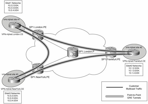
The advantage of using point-to-point GRE tunnels to transport multicast traffic between customer VPN sites is that it is not necessary to enable multicast transport within the service provider core network.
One major disadvantage of using point-to-point GRE tunnels is the fact that a mesh of tunnels is necessary to transport multicast traffic between CE routers, and if any site to any site multicast transport is required then the number of GRE tunnels required is n(n 1)/2 (where n is the number of sites). If there are 5 sites, you need 10 tunnels; if there are 50 sites, you need 1225 tunnels; and if there are 100 sites, you need 4950 tunnels. So, configuring point-to-point GRE tunnels between CE routers is an inherently unscalable solution.
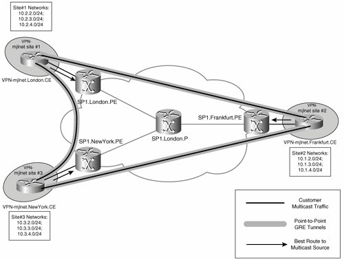
Another problem with configuring point-to-point GRE tunnels between CE routers is the fact that this causes the unicast and multicast forwarding paths to be incongruentCE routers receive unicast traffic on their physical interface connected to a PE router but receive multicast on their GRE tunnel interfaces. The fact that forwarding paths are incongruent means that without careful configuration of CE routers, reverse-path forwarding (RPF) checks fail, and multicast traffic is dropped (see Figure 5-26).
Figure 5-26. Incongruent Traffic Forwarding May Cause Multicast Traffic to Be Dropped by CE Routers
Note
RFP checks ensure that multicast traffic is received on the interface that corresponds to the shortest path to the source. If the unicast routing table is used for RPF checks and unicast and multicast forwarding paths are incongruent, multicast traffic will be dropped.
The simplest method of ensuring that CE routers do not drop multicast traffic when unicast and multicast forwarding paths are incongruent is to configure static multicast routes (ip mroute source-address mask tunnel interface-number). The static multicast route will be used for RPF checking, and will ensure that CE routers do not drop multicast traffic.
In summary, point-to-point GRE tunnels between CE routers do not offer a truly viable solution for the transport of multicast traffic between customer VPN sites.
Multicast VPNs (MVPN)
If point-to-point GRE tunnels are not a viable solution for multicast traffic transport, then what is? The answer is multicast VPNs (MVPN).
Note
Multicast transport in MPLS Layer 3 VPNs is described in Internet Draft draft-rosen-vpn-mcast at the time of this writing. MVPN is based on this Internet Draft.
MVPN avoids both of the major disadvantages of point-to-point GRE tunnels between CE routers:
- No special configuration is required on CE routers (no point-to-point GRE tunnels are required).
- CE routers receive multicast traffic on the same interface as unicast traffic, thereby ensuring that no special configuration is required to ensure that RPF checks succeed on CE routers.
There are a number of important components and considerations when deploying MVPN, including the following:
- The multicast domain (MD)
- The multicast VRF (MVRF)
- The multicast tunnel (MT) and multicast tunnel interface (MTI)
- Protocol Independent Multicast (PIM) adjacencies
- Multicast distribution trees (MDT)
- RPF checks in an MVPN
The following section discuss these components and considerations.
The Multicast VRF and Multicast Domain
An MD is a grouping of MVRFs on PE routers (and possibly ASBRs, when inter-autonomous system MVPN is configured) that send multicast traffic to and receive multicast from each other. An MVRF consists of multicast and forwarding tables corresponding to a VRF.
Figure 5-27 shows an MD.
Figure 5-27. Multicast Domain
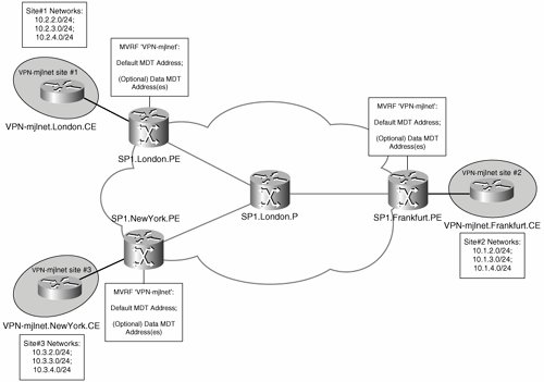
As shown in Figure 5-27, SP1.London.PE, SP1.NewYork.PE, and SP1.Frankfurt.PE are all configured with an MVRF corresponding to customer VPN VPN-mjlnet, and these MVRFs comprise one MD.
When an MVRF is configured on a PE router, an MTI is created, which allows the forwarding of multicast traffic between the local MVRF and other (remote) MVRFs in an MD. Unicast traffic is not forwarded over the MTI.
Customer multicast packets sent on the MTI are encapsulated in GRE, with the GRE packet source IP address being the BGP update source of the PE router and the destination address being a multicast address specific to the MD. The type of service (ToS) settings in customer multicast packets are copied to the outer IP packet header (IP/GRE).
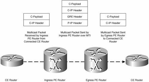
Figure 5-28 shows the form of packets send on the MTI.
Figure 5-28. Packets Sent on the MTI
Note
At the time of writing, GRE encapsulation is the only option for packets sent on the MTI. Internet Draft draft-rosen-vpn-mcast discusses the encapsulation of customer multicast traffic sent over the MT using GRE, IP, or MPLS.
Figure 5-28 shows a customer multicast packet (called a C-Packet) arriving at the ingress PE router from a connected CE router.
As previously discussed, when a C-packet is sent over the MT, it is encapsulated in GRE, with the outer IP header having a source IP address being the BGP update source of the sending PE router and the destination IP address being one corresponding to the particular MD and being significant only in the service provider backbone. Because IP addresses in the outer header are significant only in the service provider backbone, the outer header is shown as the P-IP Header in Figure 5-28.
The encapsulated C-packet arrives at the egress PE router. Because more than one MVRF may be configured on the egress PE router, the destination IP address contained in the P-IP header is used to determine the correct MVRF. After the correct MVRF has been determined, the egress PE router decapsulates the C-packet (removes the P-IP/GRE headers) and forwards the C-packet to the connected CE router.
The Default and Data MDTs
You now know that customer multicast packets are encapsulated when sent between PE routers and that the destination IP address contained in P-IP header is a multicast address. It is important to understand the multicast addresses used.
When an MD is configured, a multicast tree called the default multicast distribution tree (MDT) is automatically built between PE routers configured to participate in an MD.
When you configure a PE router to participate in an MD, it becomes a source (root) for the default MDT as well as being a receiver (leaf) for the default MDT. So, each PE router participating in an MD is both a root and a leaf node of the default MDT.
Multicast traffic sent over the default MDT by one PE router in an MD is received by all the other PE routers in that MD, as shown in Figure 5-29.
Figure 5-29. Multicast Transmission over the Default MDT
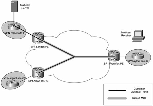
By default, all multicast traffic sent between customer sites in an MVPN is sent over the default MDT corresponding to that MVPN (MD). That includes all PIM control traffic, all PIM sparse mode multicast group traffic, and all PIM dense mode multicast group traffic.
You gain a number of advantages by sending all MVPN multicast traffic over a default MDT, including the following:
- The default MDT aggregates all customer multicast group traffic, and by extension multicast state in the service provider core network.
Because all customer multicast traffic for a particular MVPN is (by default) tunneled using a single multicast group address, core PE and P routers only need to maintain default MDT routing and forwarding information (multicast state information) for the specific MD, rather than multicast state for each individual multicast group address used within a customer MVPN.
- The default MDT can be used to transport all multicast traffic types (traffic for sparse, dense, and source-specific multicast mode groups).
Unfortunately, there is one significant disadvantage of using the default MDT to transport all customer MVPN multicast trafficall customer MVPN traffic is sent to all PE routers in the MD regardless of whether the site to which a PE router is connected has any multicast receivers for the particular multicast group in question. Figure 5-30 illustrates this issue.
Figure 5-30. Multicast Transport over the Default MDT
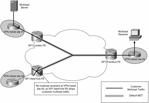
As you can see, there are receivers for the customer multicast group at VPN-mjlnet site 2 (Frankfurt), but there are no receivers at site 3 (New York). Notice, however, that traffic from the source at site 1 (London) is transported over the default MDT to all PE routers in the MD, including SP1.NewYork.PE (connected to site 3).
The default MDT, therefore, provides suboptimal multicast transport if there are not receivers for all customer MVPN groups at all sites. What is the solution to the issue of suboptimal multicast traffic transport? The answer is the configuration of data MDTs.
Note
Configuration of data MDTs is optional.
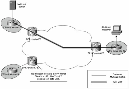
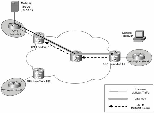
The difference between a default MDT and a data MDT is that a data MDT is constructed only between the PE connected to a high-bandwidth customer multicast source and other PE routers in the MD that are connected to sites at which there are multicast receivers for the multicast group in question. PE routers connected to sites at which there are no receivers do not join the data MDT.
Figure 5-31 illustrates a data MDT.
Figure 5-31. Data MDT
As previously mentioned, data MDTs are constructed for high-bandwidth multicast groups (high bandwidth traffic flows that correspond to [S, G] entries in the MVRF). The decision as to what constitutes a high-bandwidth multicast source is determined by the service providerthe amount of bandwidth that a multicast source needs to be sending to trigger the creation of a data MDT is configurable (on PE routers). The source can be sending as little as 1 kbps or as much as 4294967 kbps.
You might be wondering how exactly data MDTs are constructed in the service provider network. After all, unlike default MDTs where each PE router is both a root and leaf in the MDT, data MDTs are only constructed between the PEs that are connected to sites where there are receivers for a certain customer multicast group and the PE connected to the site where the source for that group resides (via a Rendezvous Point [RP] if PIM Sparse Mode [PIM-ISM] or bi-directional PIM mode is used in the provider backbone).
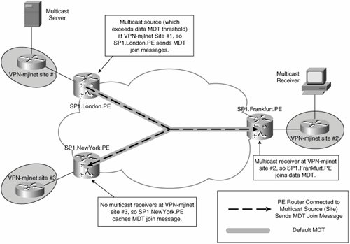
So, the leaf PEs in this case (those connected to sites where there are receivers) need to discover the root of the data MDT (the PE which is connected to the site at which the source is located) as well as other information, such as customer multicast flow information, so that they can join the MDT. To ensure that leaf PEs can discover the address of the PE connected to the source, a new message (Type Length Value [TLV]), called an MDT Join, has been introduced (see Figure 5-32).
Figure 5-32. MDT Join Message

The root PE router sends the MDT Join to all PE routers in the MD over the default MDT. The root PE router encapsulates the MDT Join message in UDP with port 3232 using destination IP address 224.0.0.13 (ALL-PIM-ROUTERS), with the MDT Join message fields described as follows:
- Type This field contains a value of 1, indicating that this message is an MDT Join.
- Length The total length of the message, not including IP and UDP headers. The length of the MDT Join is 16 bytes.
- Reserved Reserved for future use.
- C-source The customer multicast source IP address.
- C-group The customer multicast group address.
- P-group The multicast group address that the root PE router will use to send data MDT traffic.
So, the root PE advertises the customer multicast source and group addresses as well as the multicast group address the root PE router will use encapsulate the customer multicast flow to other PE routers in the MD using the MDT Join message, and interested PE routers (those connected to sites where there are receivers) join the data MDT either via the RP if PIM Sparse mode or bi-directional mode is used for data MDTs in the provider backbone, or directly to the root PE if PIM Source Specific Multicast (SSM) is used for data MDTs in the provider backbone. Noninterested PE routers (those connected to sites where there are no receivers) cache the MDT Join message information, which allows these to then quickly join the data MDT if a receiver comes on line at the connected customer VPN site.
The root PE router for the data MDT begins sending customer multicast traffic over the data MDT 3 seconds after sending the MDT Join, thus giving leaf PE routers time to join the data MDT.
Figure 5-33 shows data MDT setup.
Figure 5-33. Leaf PE Routers Join the Data MDT
It is worth noting that the root PE for a data MDT resends the MDT Join message over the default MDT every 60 seconds as long as the customer multicast source is sending traffic over the configured bandwidth threshold. If an interested PE router does not receive an MDT Join for the data MDT for 3 minutes, it deletes the corresponding multicast state information.
Also, if the customer multicast traffic rate drops below the configured threshold, this traffic remains on the data MDT for up to 60 seconds before transferring back to the default MDT. This means that oscillations in the rate at which customer multicast traffic is sent will not cause data MDTs to be created, destroyed, and created again in quick succession.
As you now know, the advantage of data MDTs is that they optimize multicast traffic flow in the service provider core network because only interested PE routers receive multicast traffic.
The disadvantage of data MDTs is that more multicast state is required in the service provider core network (there are more multicast groups).
Before finishing this section, it is important to note that PIM control traffic and dense mode multicast traffic remains on the default MDT and is never sent over a data MDT.
PIM Adjacencies
When designing and deploying MVPNs, it is important to understand the PIM adjacencies that are formed between CE, PE, and P routers.
In an MVPN, the service provider core network is transparent to customer routers. PE routers establish PIM adjacencies with CE routers in the appropriate MVRF context, so the PIM instances corresponding to each customer (MVRF) are logically separate on PE routers. PE routers also establish PIM adjacencies with other PE routers in the same MD over the MT, the MT is treated by the VPN (VRF) specific PIM instances as a LAN interface, and PIM LAN behavior is implemented on the MT. Finally, PE routers establish global PIM adjacencies with P routers.
Figure 5-34 illustrates MVPN PIM adjacencies.
Figure 5-34. MVPN PIM Adjacencies
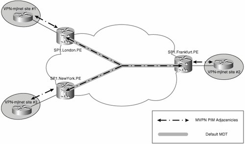
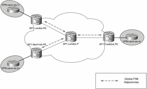
Figure 5-35 illustrates global PIM adjacencies.
Figure 5-35. Global PIM Adjacencies
Reverse-Path Forwarding Checks in the MVPN
RPF checks are used in multicast networks to ensure that multicast packets are received on the correct interface. The correct interface is that which corresponds to the best path back to the multicast source.
By default, the RPF check is based on information contained within the unicast routing table. In regular IP networks, using the unicast routing table for RPF checks works well, but using the unicast routing table can cause problems on PE routers in an MVPN.
You will remember that in an MVPN, customer multicast traffic is transported over the MT between PE routers. Unicast traffic, on the other hand, is forwarded over Label Switched Paths (LSP) or L2TPv3/GRE/IPsec tunnels between PE routers. This means that the unicast routes to customer multicast sources are reachable via LSPs or L2TPv3/GRE/IPsec tunnels across the service provider core network.
For example, in the MPLS VPN backbone network shown in Figure 5-36, the customer multicast source (10.2.1.1) is reachable via an LSP to SP1.London.PE from SP1.Frankfurt.PE. The LSP to SP1.London.PE is the regular unicast path back to the source, as dictated by a route contained in the unicast routing table.
Figure 5-36. Customer Multicast Source Is Reachable via an LSP to SP1.London.PE
The problem with the fact that the best route back to the customer multicast source is via an LSP to SP1.London.PE is that when customer multicast traffic arrives at SP1.Frankfurt.PE over the MT, and if the regular RPF check is applied, this multicast traffic would be dropped (multicast traffic is received on the MT, but the best route back to the multicast source is via the physical interface and over the LSP).
Thankfully, the multicast RPF check has been slightly modified for use in an MVPNif the interface corresponding to the best route to the source is not via an interface associated with the VRF, the MTI is instead considered to be the interface corresponding to the best route to the source for multicast traffic. By using the MTI as the RPF interface, customer multicast traffic received on the MT can now be accepted by PE routers and forwarded onward to the appropriate connected customer site.
Configuring PIM Between PE and P Routers in the Service Provider MPLS VPN Backbone Network
PIM must be enabled within the service provider MPLS VPN backbone network, but the exact choice of configuration is flexible. It is possible, for example, to configure PIM sparse mode (PIM-SM), bidirectional PIM, and PIM source-specific multicast (PIM-SSM).
If you configure PIM-SM in the service provider core network, you need one or more rendezvous points (RP).
If you use PIM-SSM, on the other hand, no RPs are required. The advantage of having no RPs is that it removes possible points of failure from the network (the RPs), reduces the complexity of the multicast configuration in the core network, and reduces multicast forwarding delay because (initially) multicast traffic is sent over a shared tree rooted at the RP in a PIM-SM environment. PIM-SSM is often particularly recommended for data MDTs because otherwise a large number of unique multicast (P-) addresses may be required for each MD. Furthermore, in order that amount of multicast routing state is kept to a minimum on P routers, it is often recommended that default MDTs use shared trees (such as PIM bidirectional trees).
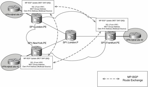
If PIM-SM or bi-directional PIM is used to establish a default MDT, PE routers only need to know the default MDT (P-group) address in order to start establishing the default MDT (other PE routers' addresses can then be discovered when PIM traffic is received). If PIM-SSM is used to establish MDTs, on the other hand, every PE router must know the source address of every other PE router in the MD before MDT establishment can start.
PE routers in an MD can discover each other's addresses by signaling this information using MP-BGP.
Prior to Cisco IOS Software Release 12.0(29)S, PE routers signal this information (as well as the default MDT group address) using a BGP update containing extended community attribute 0x0009 and an MP_REACH_NRLI attribute. A type 0x0002 Route Distinguisher (RD) is carried in the update.
Figure 5-37 illustrates PE router auto-discovery in Cisco IOS versions prior to Release 12.0(29).
Figure 5-37. Signaling of the Default MDT Group Address and Root Address in Cisco IOS Software Prior to Release 12.0(29)
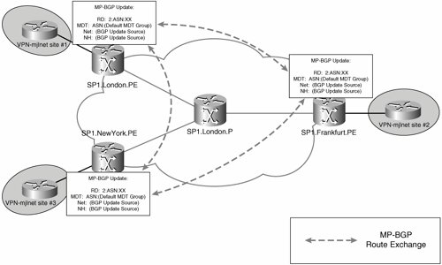
As shown in Figure 5-37, PE routers in the MD that are configured to use PIM-SSM use the information carried in the BGP update to directly join the default MDT (rooted at other PE routers). If a PE router is not configured to use PIM-SSM, it simply caches the information contained in the update message.
The method of distribution of the default MDT information used prior to Cisco IOS Release 12.0(29)S is limited to a single autonomous system.
In Cisco IOS Software Release 12.0(29)S, a new BGP address family (subsequent address family indicator [SAFI] 66) is used to signal default MDT information between PE routers (see Figure 5-38).
Figure 5-38. MDT SAFI MP_REACH_NRLI
Note
Cisco IOS Software Release 12.0(29)S is backward compatible with previous Cisco IOS versions for the advertisement of default MDT information.
Advantages of Deploying MVPN
MVPN has a number of advantages when compared to using a mesh of GRE tunnels between CE routers to transport multicast traffic. These advantages include the following:
- MVPN is scalable because a mesh of point-to-point GRE tunnels is not required.
- MVPN does not require special configuration within the customer network (either on C or CE routers). Existing multicast configuration within the customer network can be maintained.
Configuring and Verifying MVPN
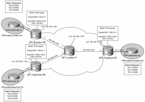
Now that you know how MVPN works in theory, it is time to take a look at how it works in practice. Figure 5-39 shows a sample MVPN deployment that is used to illustrate configurations throughout this section.
Figure 5-39. Sample MVPN Deployment
Configuring MVPN
Example 5-29 shows the configuration for MVPN on a PE router (SP1.London.PE). Note that the configuration for MVPN on SP1.Frankfurt.PE and SP1.NewYork.PE is the same for MVPN.
Example 5-29. Configuration for MVPN on SP1.London.PE
! ! On SP1.London.PE (line 1) ! ip vrf VPN-mjlnet (line 2) rd 65535:100 route-target export 65535:100 route-target import 65535:100 mdt default 239.0.0.1 (line 3) mdt data 239.0.100.0 0.0.0.255 threshold 1 (line 4) ! ip multicast-routing (line 5) ip multicast-routing vrf VPN-mjlnet (line 6) ! interface Loopback0 ip address 192.168.1.2 255.255.255.255 ip pim sparse-dense-mode ! interface Serial2/0 ip address 192.168.2.1 255.255.255.0 ip pim sparse-mode (line 7) tag-switching ip ! interface Serial2/1 ip vrf forwarding VPN-mjlnet (line 8) ip address 10.2.1.2 255.255.255.0 ip pim sparse-dense-mode (line 9) ! router bgp 65535 (line 10) no synchronization neighbor 192.168.1.1 remote-as 65535 neighbor 192.168.1.1 update-source Loopback0 neighbor 192.168.1.3 remote-as 65535 neighbor 192.168.1.3 update-source Loopback0 no auto-summary ! address-family ipv4 mdt (line 11) neighbor 192.168.1.1 activate (line 12) neighbor 192.168.1.3 activate (line 13) exit-address-family ! address-family vpnv4 neighbor 192.168.1.1 activate neighbor 192.168.1.1 send-community extended neighbor 192.168.1.3 activate neighbor 192.168.1.3 send-community extended exit-address-family ! address-family ipv4 vrf VPN-mjlnet neighbor 10.2.1.1 remote-as 64512 neighbor 10.2.1.1 activate neighbor 10.2.1.1 as-override no auto-summary no synchronization exit-address-family ! ip pim ssm range 50 (line 14) ! access-list 50 permit 239.0.0.0 0.0.255.255 (line 15) ! |
In highlighted line 3, the default MDT address for VRF VPN-mjlnet is configured as 239.0.0.1 using the mdt default group-address command. The default MDT address must match between all VRFs in the MVPN (all VPN-mjlnet VRFs configured on all PE routers).
The MTI for the MPVN is created by the mdt default group-address command. The source address of default MDT (P-) packets will be the BGP update source address (the loopback interface), and the destination address will be the configured group address.
The address range for data MDTs is configured in highlighted line 4 (239.0.100.0 to 239.0.100.255) using the mdt data group-address-range wildcard-bits [threshold bandwidth-threshold-value [list access-list]] command. Remember that the data MDTs are optional but recommended if customers have high-bandwidth multicast sources that send traffic over the MPLS VPN backbone network.
The group address range configured using the mdt data group-address-range wildcard-bits [threshold threshold-value [list access-list]] constitutes a pool of addresses from which data MDT groups are chosen. A data MDT group address is chosen when traffic for a particular customer multicast group (that matches the addresses specified in the access list) exceeds the configured threshold. The source address for a data MDT's (P-) packets is the BGP update source, and the destination address corresponds to the group address selected from the configured data MDT group address range.
Note
Recommended practice dictates that all MDT group addresses (P-group addresses) be in the range of administratively scoped multicast addresses (that is, 239.0.0.0 to 239.255.255.255 [see RFC2365]). This will ensure that if the service provider is providing Internet multicast service the MDT group addresses will not overlap.
In highlighted line 5, the ip multicast-routing command is used to enable IP multicast on the SP1.London.PE. The ip multicast-routing vrf vrf-name command is used to enable IP multicast for VRF VPN-mjlnet in highlighted line 6.
Next, the ip pim sparse-mode command is used to enable PIM sparse mode on an MPLS VPN backbone interface (an interface connected to a P router/other PE router) in highlighted line 7. Note that in this example, SSM is used within the SP1 MPLS VPN backbone network, but if you choose to enable PIM sparse mode with auto-RP, you will need to configure PIM sparse-dense mode using the ip pim sparse-dense mode command.
Also notice the ip pim-sparse-dense mode command configured on interface Loopback0 (the MP-BGP update source). Make sure that you enable PIM on the MP-BGP update source; otherwise, MVPN will fail to operate correctly.
Note
The ip pim autorp listener global configuration mode command can be used from Cisco IOS version 12.2(7) to enable auto-RP to operate on PIM sparse mode interfaces.
Highlighted line 9 shows the ip pim sparse-dense mode command on a VRF VPN-mjlnet interface. The PIM mode that is enabled on VRF interfaces will depend on the customer multicast configuration, but the configuration of the ip pim sparse-dense mode command on VRF interfaces allows the greatest flexibility.
In highlighted line 11, the address-family ipv4 mdt command is used to enter the IPv4 MDT address family configuration mode.
Then, in highlighted lines 12 and 13, the neighbor ip-address activate command is used within the IPv4 MDT address family to enable the signaling of default MDT source address and group address with the specified PE routers using the new BGP subsequent address family (SAFI 66). Remember that the signaling of the source address of the default MDT is only necessary when using SSM within the MPLS VPN backbone network.
Note
The address-family ipv4 mdt command was added in Cisco IOS Software Release 12.0(29)S.
The ip pim ssm range access-list command (highlighted line 14) is used to define the range of multicast addresses to be used for SSM within the MPLS VPN backbone. In this case, the actual multicast addresses are specified using access-list 50 in highlighted line 15 (multicast address range 239.0.0.0 to 239.0.255.255).
The ip pim ssm range command is necessary only when using SSM in the MPLS VPN backbone. Make sure that the range of multicast addresses specified using this command includes those group addresses configured using the mdt default and mdt data commands when using SSM for default and data MDTs.
As shown in Example 5-30, the configuration required on P routers (SP1.London.P) to support MVPN is much simpler than that required for PE routers.
The ip multicast-routing command in highlighted line 2 is used to enable global multicast on SP1.London.P.
Example 5-30. Configuration Required on P Routers to Support MVPN
! ! On SP1.London.P (line 1) ! ip multicast-routing (line 2) ! interface FastEthernet0/0 ip address 192.168.3.2 255.255.255.0 ip pim sparse-mode (line 3) tag-switching ip ! interface Serial1/0 ip address 192.168.2.2 255.255.255.0 ip pim sparse-mode (line 4) tag-switching ip ! interface Serial1/1 ip address 192.168.4.1 255.255.255.0 ip pim sparse-mode (line 5) tag-switching ip ! ip pim ssm range 50 (line 6) ! access-list 50 permit 239.0.0.0 0.0.255.255 (line 7) ! |
In highlighted lines 3, 4, and 5, the ip pim sparse-mode command is used to enable PIM sparse mode on the interfaces connected to other P routers and PE routers. Again, if auto-RP is used in the MPLS VPN backbone, you must configure the ip pim sparse-dense-mode command or (in Cisco IOS Software Release 12.2(7) and later) configure the ip pim autorp listener global configuration mode command to enable auto-RP to operate on PIM sparse mode interfaces.
In this example, PIM SSM is used within the MPLS VPN backbone, and the ip pim ssm range access-list command shown in highlighted line 6 is used to define the range of multicast addresses to be used for SSM. The multicast addresses are specified using access-list 50 (see highlighted line 7) and include those group addresses configured using the mdt default and mdt data commands on the PE routers.
Verifying PIM Adjacencies
PE routers maintain global PIM adjacencies with P routers (and with any directly connected PE routers) as well as MVRF PIM adjacencies with other PE routers on their MTIs and with directly connected CE routers on their VRF interfaces. You can display global PIM adjacencies using the show ip pim neighbors command, as shown in Example 5-31.
Example 5-31. Verifying Global PIM Neighbors Using the show ip pim neighbors Command
SP1.London.PE#show ip pim neighbors PIM Neighbor Table Neighbor Interface Uptime/Expires Ver DR Address Priority/Mode 192.168.2.2 Serial2/0 00:06:12/00:01:26 v2 1 / SP1.London.PE# |
As you can see, SP1.London.PE has one global PIM neighbor on core MPLS VPN backbone interface serial 2/0 (SP1.London.P, 192.168.2.2).
On the other hand, SP1.London.PE has three MVRF VPN-mjlnet PIM adjacencies (see Example 5-32).
Example 5-32. Verifying MVRF PIM Neighbors Using the show ip pim vrf Command
SP1.London.PE#show ip pim vrf VPN-mjlnet neighbor PIM Neighbor Table Neighbor Interface Uptime/Expires Ver DR Address Priority/Mode 10.2.1.1 Serial2/1 00:06:30/00:01:44 v2 1 / 192.168.1.1 Tunnel0 00:02:35/00:01:37 v2 1 / V 192.168.1.3 Tunnel0 00:04:03/00:01:38 v2 1 / DR V SP1.London.PE# |
The three MVRF VPN-mjlnet PIM adjacencies are with 10.2.1.1 (VPN-mjlnet.London.CE on interface serial 2/1), with 192.168.1.1 (SP1.NewYork.PE on interface tunnel 0 [the MTI]), and with 192.168.1.3 (SP1.Frankfurt.PE on interface tunnel 0 [MTI]). If you are wondering why there are no MVRF PIM adjacencies on core MPLS VPN backbone interfaces (interface serial 2/0), remember that MVRF PIM adjacencies are only established with remote PE routers on their MTIs and with CE routers on VRF interfaces.
Although not shown here, SP1.Frankfurt.PE and SP1.NewYork.PE similarly each maintain two PIM adjacencies over their MTIs (with the other two PE routers) and a single PIM adjacency with the directly connected CE router (VPN-mjlnet.Frankfurt.CE and VPN-mjlnet.NewYork.CE, respectively).
Example 5-33 shows the PIM neighbor table on SP1.London.P.
Example 5-33. The PIM Neighbor Table on SP1.London.P
SP1.London_P#show ip pim neighbor PIM Neighbor Table Neighbor Interface Uptime/Expires Ver DR Address Priority/Mode 192.168.3.1 FastEthernet0/0 00:07:36/00:01:31 v2 1 / 192.168.2.1 Serial1/0 00:08:23/00:01:15 v2 1 / 192.168.4.2 Serial1/1 00:08:02/00:01:33 v2 1 / SP1.London_P# |
SP1.London.P has PIM neighbors on interface Fast Ethernet 0/0 (192.168.3.1, SP1.NewYork.PE), serial 1/0 (192.168.2.1, SP1.London.PE), and serial 1/1 (192.168.4.2, SP1.Frankfurt.PE).
Verifying the Signaling of the Default MDT
As previously mentioned, PE routers running Cisco IOS Software Release 12.0(29)S and later can advertise the source and group addresses used for the default MDT with the MDT SAFI.
You can verify the negotiation of the MDT SAFI capability between PE routers with the show ip bgp neighbors [neighbor-address] command, as demonstrated for SP1.London.PE in Example 5-34.
Example 5-34. Verifying Negotiation of the MDT SAFI Capability Between PE Routers
SP1.London.PE#show ip bgp neighbors 192.168.1.3 | begin MDT Address family IPv4 MDT: advertised and received Address family VPNv4 Unicast: advertised and received Message statistics: InQ depth is 0 OutQ depth is 0 Sent Rcvd Opens: 1 1 Notifications: 0 0 Updates: 0 8 Keepalives: 23 23 Route Refresh: 0 0 Total: 30 32 Default minimum time between advertisement runs is 5 seconds SP1.London.PE# |
The highlighted line shows that MDT SAFI capability has been negotiated with SP1.Frankfurt.PE. The word advertised indicates that the local PE router (SP1.London.PE) supports this capability and has advertised this to SP1.NewYork.PE. The word received indicates that SP1.NewYork.PE supports this capability and has advertised this to the local PE router.
Again, although not shown here, all PE routers are running Cisco IOS Software Release 12.0(29)S or later and similarly negotiate MDT SAFI capability with each other. The PE routers then advertise source and destination default MDT addresses to each other.
You can verify default MDT groups using the show ip bgp ipv4 mdt all command, as demonstrated for SP1.London.PE in Example 5-35. As seen in highlighted line 1, the RD associated with the MDT default group advertised between PE routers for VRF VPN-mjlnet is 65535:100.
Example 5-35. Verifying Default MDT Groups
SP1.London.PE#show ip bgp ipv4 mdt all BGP table version is 5, local router ID is 192.168.1.2 Status codes: s suppressed, d damped, h history, * valid, > best, i - internal, r RIB-failure, S Stale Origin codes: i - IGP, e - EGP, ? - incomplete Network Next Hop Metric LocPrf Weight Path Route Distinguisher: 65535:100 (default for vrf VPN-mjlnet) (line 1) *>i192.168.1.1/32 192.168.1.1 0 100 0 ? (line 2) *> 192.168.1.2/32 0.0.0.0 0 ? (line 3) *>i192.168.1.3/32 192.168.1.3 0 100 0 ? (line 4) SP1.London_PE# |
In highlighted lines 2 to 4, you can see the default MDT source addresses advertised by each of the three PE routers in the VPN-mjlnet multicast domain (192.168.1.1 [SP1.NewYork.PE], 192.168.1.2 [SP1.London.PE, the local PE router], and 192.168.1.3 [SP1.Frankfurt.PE]).
You can use the show ip bgp ipv4 mdt all ip-address command to see more information regarding default MDT advertisement between PE routers, as demonstrated in Example 5-36 for SP1.London.PE.
Example 5-36. Displaying More Information Regarding Default MDT Advertisement Between PE Routers
SP1.London.PE#show ip bgp ipv4 mdt all 192.168.1.1
BGP routing table entry for 65535:100:192.168.1.1/32, version 5 (line 1)
Paths: (1 available, best #1, table IPv4-MDT-BGP-Table)
 Not advertised to any peer
 Local
 192.168.1.1 (metric 30) from 192.168.1.1 (192.168.1.1)
 Origin incomplete, metric 0, localpref 100, valid, internal, best,
 MDT group address: 239.0.0.1 (line 2)

SP1.London.PE#
SP1.London.PE#show ip bgp ipv4 mdt all 192.168.1.3 BGP routing table entry for 65535:100:192.168.1.3/32, version 4 (line 3) Paths: (1 available, best #1, table IPv4-MDT-BGP-Table) Not advertised to any peer Local 192.168.1.3 (metric 30) from 192.168.1.3 (192.168.1.3) Origin incomplete, metric 0, localpref 100, valid, internal, best, MDT group address: 239.0.0.1 (line 4) SP1.London.PE# |
Highlighted lines 1 and 2 show that SP1.NewYork.PE is advertising source 192.168.1.1 for default MDT group address 239.0.0.1.
In highlighted lines 3 and 4, you can see that SP1.Frankfurt.PE is advertising source 192.168.1.3 for default MDT group 239.0.0.1.
Verifying Multicast Traffic Flow
You can verify multicast traffic flow across the MPLS VPN backbone by examining the multicast routing table on PE and P routers using the show ip mroute command.
Example 5-37 shows the output of the show ip mroute command on SP1.London.PE.
Example 5-37. Multicast Routing Table on SP1.London.PE
SP1.London.PE#show ip mroute IP Multicast Routing Table Flags: D - Dense, S - Sparse, B - Bidir Group, s - SSM Group, C - Connected, L - Local, P - Pruned, R - RP-bit set, F - Register flag, T - SPT-bit set, J - Join SPT, M - MSDP created entry, X - Proxy Join Timer Running, A - Candidate for MSDP Advertisement, U - URD, I - Received Source Specific Host Report, Z - Multicast Tunnel, Y - Joined MDT-data group, y - Sending to MDT-data group V - RD & Vector, v - Vector Outgoing interface flags: H - Hardware switched, A - Assert winner Timers: Uptime/Expires Interface state: Interface, Next-Hop or VCD, State/Mode (192.168.1.1, 239.0.0.1), 00:02:01/00:02:57, flags: sTIZ (line 1) Incoming interface: Serial2/0, RPF nbr 192.168.2.2 Outgoing interface list: MVRF VPN-mjlnet, Forward/Sparse, 00:02:01/00:00:58 (192.168.1.2, 239.0.0.1), 00:05:52/00:03:17, flags: sTZ (line 2) Incoming interface: Loopback0, RPF nbr 0.0.0.0 Outgoing interface list: Serial2/0, Forward/Sparse, 00:03:51/00:02:35 (192.168.1.3, 239.0.0.1), 00:03:31/00:02:56, flags: sTIZ (line 3) Incoming interface: Serial2/0, RPF nbr 192.168.2.2 Outgoing interface list: MVRF VPN-mjlnet, Forward/Sparse, 00:03:31/00:00:00 (192.168.1.1, 239.0.100.0), 00:01:49/00:02:57, flags: sTIZ (line 4) Incoming interface: Serial2/0, RPF nbr 192.168.2.2 Outgoing interface list: MVRF VPN-mjlnet, Forward/Sparse, 00:01:49/00:01:11 (192.168.1.2, 239.0.100.0), 00:01:29/00:03:27, flags: sTZ (line 5) Incoming interface: Loopback0, RPF nbr 0.0.0.0 Outgoing interface list: Serial2/0, Forward/Sparse, 00:01:29/00:02:34 (line 6) (*, 224.0.1.40), 00:05:56/00:02:56, RP 0.0.0.0, flags: DCL Incoming interface: Null, RPF nbr 0.0.0.0 Outgoing interface list: Loopback0, Forward/Sparse, 00:05:54/00:02:56 SP1.London.PE# |
Highlighted lines 1, 2, and 3 show the default MDT source and group addresses advertised by PE routers SP1.NewYork.PE, SP1.London.PE (the local PE router), and SP1.Frankfurt.PE. Take a close look at the flags shownnote, in particular, the s flag, which indicates that these multicast routing table entries correspond to SSM groups, and the Z flag, which indicates that these entries are MDT entries and that packets corresponding to these entries should be sent and received on the MTI.
Highlighted lines 4 and 5 show entries for data MDTs (192.168.1.1, 239.0.100.0 and 192.168.1.2, 239.0.100.0). Notice that the outgoing interface list for SSM group 192.168.1.2, 239.0.100.0 contains interface serial 2/0. This is because a (high-bandwidth) source at VPN-mjlnet site 1 (London) is sending traffic on this data MDT over the MPLS VPN backbone.
Example 5-38 shows the multicast routing table on SP1.London.PE.
Example 5-38. Multicast Routing Table on SP1.London.PE
SP1.London.P#show ip mroute IP Multicast Routing Table Flags: D - Dense, S - Sparse, B - Bidir Group, s - SSM Group, C - Connected, L - Local, P - Pruned, R - RP-bit set, F - Register flag, T - SPT-bit set, J - Join SPT, M - MSDP created entry, X - Proxy Join Timer Running, A - Candidate for MSDP Advertisement, U - URD, I - Received Source Specific Host Report, Z - Multicast Tunnel, Y - Joined MDT-data group, y - Sending to MDT-data group Outgoing interface flags: H - Hardware switched Timers: Uptime/Expires Interface state: Interface, Next-Hop or VCD, State/Mode (192.168.1.1, 239.0.0.1), 00:04:25/00:03:25, flags: sT (line 1) Incoming interface: FastEthernet0/0, RPF nbr 192.168.3.1 Outgoing interface list: Serial1/0, Forward/Sparse, 00:04:25/00:03:07 Serial1/1, Forward/Sparse, 00:04:25/00:03:25 (192.168.1.2, 239.0.0.1), 00:06:14/00:03:25, flags: sT (line 2) Incoming interface: Serial1/0, RPF nbr 192.168.2.1 Outgoing interface list: Serial1/1, Forward/Sparse, 00:06:14/00:03:25 FastEthernet0/0, Forward/Sparse, 00:06:14/00:02:59 (192.168.1.3, 239.0.0.1), 00:05:54/00:03:15, flags: sT (line 3) Incoming interface: Serial1/1, RPF nbr 192.168.4.2 Outgoing interface list: Serial1/0, Forward/Sparse, 00:05:54/00:03:07 FastEthernet0/0, Forward/Sparse, 00:05:54/00:02:58 (192.168.1.1, 239.0.100.0), 00:04:11/00:03:26, flags: sT (line 4) Incoming interface: FastEthernet0/0, RPF nbr 192.168.3.1 Outgoing interface list: Serial1/0, Forward/Sparse, 00:04:11/00:03:15 (192.168.1.2, 239.0.100.0), 00:03:52/00:03:25, flags: sT (line 5) Incoming interface: Serial1/0, RPF nbr 192.168.2.1 Outgoing interface list: FastEthernet0/0, Forward/Sparse, 00:03:52/00:03:12 (*, 224.0.1.40), 00:15:58/stopped, RP 0.0.0.0, flags: DCL Incoming interface: Null, RPF nbr 0.0.0.0 Outgoing interface list: Serial1/0, Forward/Sparse, 00:07:46/00:00:00 SP1.London.P# |
Highlighted lines 1, 2, and 3 show the three SSM groups corresponding to the default MDT sourced from PE routers SP1.NewYork.PE (192.168.1.1), SP1.London.PE (192.168.1.2), and SP1.Frankfurt.PE (192.168.1.3). Notice that the outgoing interface list for each default MDT contains the interfaces toward the other two PE routers (and the incoming interface list contains the interface toward the source PE router).
For example, the default MDT sourced from address 192.168.1.1 (SP1.NewYork.PE) has an outgoing interface list containing interfaces Serial1/0 (toward SP1.London.PE) and Serial1/1 (toward SP1.Frankfurt.PE). The incoming interface list contains interface FastEthernet0/0 (toward SP1.NewYork.PE).
In highlighted line 4, you can see a data MDT with source address 192.168.1.1 and group address 239.0.100.0. If you look at the outgoing interface list, you can see that it contains interface Serial1/0 (toward SP1.London.PE), and the incoming interface list contains interface FastEthernet0/0 (toward SP1.NewYork.PE). So, there is a (high-bandwidth) source at VPN-mjlnet site 3 (New York) that is sending multicast traffic to a receiver at VPN-mjlnet site 1 (London) over this data MDT.
Finally, highlighted line 5 shows a data MDT with source address 192.168.1.2 (SP1.London.PE) and group address 239.0.100.0. The outgoing interface list for this group contains interface FastEthernet0/0 (toward SP1.NewYork.PE), and the incoming interface list contains interface Serial1/0 (toward SP1.London.PE). You can conclude from this information that there is a (high-bandwidth) multicast source at VPN-mjlnet site 1 (London) that is sending traffic to a receiver at VPN-mjlnet site 3 (New York) over this data MDT.
Part I: Understanding VPN Technology
What Is a Virtual Private Network?
- What Is a Virtual Private Network?
- VPN Devices
- Deploying Site-to-Site and Remote Access VPNs: A Comparison
- Summary
- Review Questions
Part II: Site-to-Site VPNs
Designing and Deploying L2TPv3-Based Layer 2 VPNs
- Designing and Deploying L2TPv3-Based Layer 2 VPNs
- Benefits and Drawbacks of L2TPv3-Based L2VPNs
- L2TPv3 Pseudowire Operation
- Configuring and Verifying L2TPv3 Pseudowires
- Summary
- Review Questions
Designing and Implementing AToM-Based Layer 2 VPNs
- Designing and Implementing AToM-Based Layer 2 VPNs
- Benefits and Drawbacks of AToM-Based L2VPNs
- AToM Pseudowire Operation
- Deploying AToM Pseudowires
- Implementing Advanced AToM Features
- Summary
- Review Questions
Designing MPLS Layer 3 Site-to-Site VPNs
- Designing MPLS Layer 3 Site-to-Site VPNs
- Advantages and Disadvantages of MPLS Layer 3 VPNs
- MPLS Layer 3 VPNs Overview
- A Detailed Examination of MPLS Layer 3 VPNs
- Deploying MPLS Layer 3 VPNs
- Summary
- Review Questions
Advanced MPLS Layer 3 VPN Deployment Considerations
- Advanced MPLS Layer 3 VPN Deployment Considerations
- The Carriers Carrier Architecture
- The Inter-Autonomous System/Interprovider MPLS VPN Architecture
- Supporting Multicast Transport in MPLS Layer 3 VPNs
- Implementing QoS for MPLS Layer 3 VPNs
- Supporting IPv6 Traffic Transport in MPLS Layer 3 VPNs Using 6VPE
- Summary
- Review Questions
Deploying Site-to-Site IPsec VPNs
- Deploying Site-to-Site IPsec VPNs
- Advantages and Disadvantages of IPsec Site-to-Site VPNs
- IPsec: A Security Architecture for IP
- Deploying IPsec VPNs: Fundamental Considerations
- Summary
- Review Questions
Scaling and Optimizing IPsec VPNs
- Scaling and Optimizing IPsec VPNs
- Scaling IPsec Virtual Private Networks
- Ensuring High Availability in an IPsec VPN
- Designing QoS for IPsec VPNs
- MTU and Fragmentation Considerations in an IPsec VPN
- Summary
- Review Questions
Part III: Remote Access VPNs
Designing and Implementing L2TPv2 and L2TPv3 Remote Access VPNs
- Designing and Implementing L2TPv2 and L2TPv3 Remote Access VPNs
- Benefits and Drawbacks of L2TP Remote Access VPNs
- Operation of L2TP Voluntary/Client-Initiated Tunnel Mode
- Implementing L2TP Voluntary/Client-Initiated Tunnel Mode Remote Access VPNs
- Designing and Implementing L2TP Compulsory/NAS-Initiated Tunnel Mode Remote Access VPNs
- Integrating L2TP Remote Access VPNs with MPLS VPNs
- Summary
- Review Questions
Designing and Deploying IPsec Remote Access and Teleworker VPNs
- Designing and Deploying IPsec Remote Access and Teleworker VPNs
- Comparing IPsec Remote Access VPNs with Other Types of Remote Access VPNs
- Understanding IKE in an IPsec Remote Access VPN Environment
- Deploying IPsec Remote Access VPNs Using Preshared Key and Digital Signature Authentication
- Summary
- Review Questions
Designing and Building SSL Remote Access VPNs (WebVPN)
- Designing and Building SSL Remote Access VPNs (WebVPN)
- Comparing SSL VPNs to Other Types of Remote Access VPNs
- Understanding the Operation of SSL Remote Access VPNs
- Using Clientless SSL Remote Access VPNs (WebVPN) on the Cisco VPN 3000 Concentrator
- Implementing Full Network Access Using the Cisco SSL VPN Client
- Strengthening SSL Remote Access VPNs Security by Implementing Cisco Secure Desktop
- Enabling SSL VPNs (WebVPN) on Cisco IOS Devices
- Deploying SSL VPNs (WebVPN) on the ASA 5500
- Summary
- Review Questions
Part IV: Appendixes
Designing and Building SSL Remote Access VPNs (WebVPN)
- Designing and Building SSL Remote Access VPNs (WebVPN)
- Appendix A. VPLS and IPLS Layer 2 VPNs
- Understanding VPLS
- Understanding IPLS
- Summary: Comparing VPLS and IPLS
Appendix B. Answers to Review Questions
EAN: 2147483647
Pages: 124
