AToM Pseudowire Operation
When deploying AToM, it is essential to understand how pseudowires are set up, and how frames, cells, or SDUs received on attachment circuits are transported over pseudowires.
Note
AToM pseudowires are sometimes referred to as Draft Martini pseudowires because the original Internet drafts that defined LDP-signaled MPLS pseudowires were draft-martini-l2circuit-encap-mpls ("Encapsulation Methods for Transport of Layer 2 Frames over IP and MPLS Networks") and draft-martini-l2circuit-trans-mpls ("Transport of Layer 2 Frames over MPLS").
There are two channels, or planes, of communication for AToM pseudowires:
- The control channel LDP messages are used to set up, maintain, and tear down AToM pseudowires.
- The data channel Frames, cells, or SDUs received on an attachment circuit are encapsulated and sent over the pseudowire to the peer PE router.
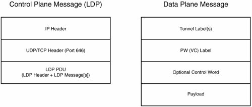
Figure 3-2 illustrates overall packet formats for control channel and data channel packets used with AToM.
Figure 3-2. Packet Formats for Control Channel and Data Channel Packets Used with AToM
The sections that follow discuss control channel and data channel messages in more detail.
Control Channel Messages
As shown in Figure 3-2, an LDP message consists of the following elements:
- An IP header and UDP or TCP header An LDP message is carried over either UDP or TCP, but in both cases, port 646 is used.
- An LDP Protocol Data Unit (PDU) This consists of an LDP header, together with one or more LDP messages.
Figure 3-3 shows the format of the LDP header.
Figure 3-3. LDP Header Format
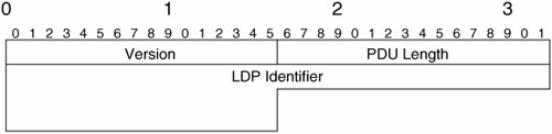
The LDP header (Figure 3-3) consists of three fields:
- Version This specifies the version of LDP. At the time of this writing, there is only one version of LDP (version 1).
- PDU Length This is the length of the PDU, with the exception of the Version and PDU Length fields.
- LDP Identifier This field functions as a unique identifier of the label space of a Label Switching Router (LSR)/Provider Edge (PE) router. A label space is a pool of labels, and this pool can either be used for a particular interface or for a platform as a whole.
An LDP Identifier is 6 octets long, with the first 4 octets being a globally unique value (these 4 octets often correspond to an IP address), and the last 2 octets identifying the label space of the LSR. If a platform-wide label space is used, the last 2 octets are 0.
Figure 3-4 shows the LDP message format.
Figure 3-4. LDP Message Format
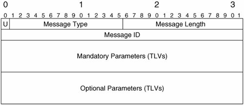
The LDP message format has the following fields:
- U The Unknown message bit. This can be set either to 1 or 0.
- Message Type The LDP message type. Table 3-1 shows possible LDP message types.
- Message Length The length of the Message ID, Mandatory Parameters, and Optional Parameters fields.
- Message ID This is an identifier for this message. This ID can be used in Notification messages to indicate the message to which they correspond.
- Mandatory Parameters These are parameters that must be included with this message.
- Optional Parameters These are parameters that may be included with this message.
|
LDP Message Type |
Description |
|---|---|
|
Notification |
This message is used to inform a peer of a significant event, such as an error. |
|
Hello |
Hello messages are exchanged as part of the LDP discovery process. |
|
Initialization |
These messages are exchanged during LDP session initialization. |
|
Keepalive |
Keepalive messages are used to verify that an LDP session is active. |
|
Address |
An LSR uses this message to advertise its interface addresses. |
|
Address Withdraw |
Used to withdraw interfaces addresses previously advertised in an Address message. |
|
Label Mapping |
Used to advertise Forwarding Equivalence Class (FEC) to label bindings. |
|
Label Request |
This message is used to request label bindings from LDP peers. |
|
Label Abort Request |
This is used to abort a label request (requested using a Label Request message). |
|
Label Withdraw |
Used to withdraw a previously advertised label binding. |
|
Label Release |
Used to communicate the fact that the sender no longer requires a label binding (which has already been advertised by an LDP peer or requested by the local LSR). |
As shown in Table 3-1, there are 11 possible LDP message types. These message types fall into 4 categories:
- Discovery messages These messages are used by an LSR to announce its presence to other LSRs, and once announced, maintain that presence.
- Session messages Session messages are used by LSRs to establish, maintain, and tear down LDP sessions.
- Advertisement messages Advertisement messages are used to distribute, modify, and delete label bindings.
- Error messages These messages are used to signal error information.
LDP discovery messages are sent over UDP (see Figure 3-2), but all other types of messages are sent over TCP.
Now that you are familiar with the overall LDP message format, it is time to take a look at AToM pseudowire setup, maintenance, and teardown.
AToM Pseudowire Setup
As previously mentioned, AToM uses LDP to set up, maintain, and tear down pseudowires.
Figure 3-5 illustrates AToM pseudowire setup.
Figure 3-5. AToM Pseudowire Setup
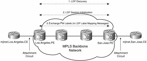
As you can see in Figure 3-5, AToM pseudowire setup consists of three steps:
|
Step 1. |
LDP discovery |
|
Step 2. |
LDP session initialization (and establishment) |
|
Step 3. |
LDP Label Mapping message (pseudowire [VC] label bindings) exchange |
LDP discovery consists of the exchange of Hello messages between the peer PE routers (the pseudowire endpoints). These Hello messages serve to make the PE routers aware of each other's existence.
LDP discovery can be performed in two different ways:
- Basic discovery This is performed between directly connected peers (at the data link layer), and uses the all routers on this subnet multicast address of 224.0.0.2.
- Extended discovery Extended discovery uses unicast (targeted Hello) transmission between peers.
In the case of LDP discovery between AToM PE routers, extended discovery is used because the peers are typically not directly connected.
In Example 3-1, you can see LDP extended discovery between peer Cisco PE routers.
Example 3-1. LDP Extended Discovery Between Peer Cisco PE Routers
San.Jose.PE#show mpls ldp discovery detail Local LDP Identifier: 10.1.1.2:0 Discovery Sources: Interfaces: Serial4/0 (ldp): xmit/recv Hello interval: 5000 ms; Transport IP addr: 10.1.1.2 LDP Id: 10.1.1.4:0 Src IP addr: 10.4.1.1; Transport IP addr: 10.1.1.4 Hold time: 15 sec; Proposed local/peer: 15/15 sec Targeted Hellos: (line 1) 10.1.1.2 -> 10.1.1.1 (ldp): active/passive, xmit/recv (line 2) Hello interval: 10000 ms; Transport IP addr: 10.1.1.2 LDP Id: 10.1.1.1:0 Src IP addr: 10.1.1.1; Transport IP addr: 10.1.1.1 Hold time: 90 sec; Proposed local/peer: 90/90 sec San.Jose.PE# |
In highlighted lines 1 and 2, you can see that targeted LDP Hellos have been exchanged between the local PE router (10.1.1.2) and the remote PE router (10.1.1.1). This exchange of targeted Hellos is the basis of LDP extended discovery. Note that detailed, step-by-step information on verifying and troubleshooting AToM-based L2VPNs can be found in Troubleshooting Virtual Private Networks by Mark Lewis (Cisco Press).
After the PE routers are aware of each other, they can establish a transport connection and begin LDP session initialization.
During the session initialization process, the PE routers negotiate session parameters such as LDP version, label distribution method, and timers. After the initialization process is finished, an LDP session is established between the PE routers, and they are considered to be LDP peers.
You can use show mpls ldp neighbor neighbor-ip-address detail to examine LDP session information on Cisco PE routers, as demonstrated in Example 3-2.
Example 3-2. Examining LDP Session Information
San.Jose.PE#show mpls ldp neighbor 10.1.1.1 detail Peer LDP Ident: 10.1.1.1:0; Local LDP Ident 10.1.1.2:0 (line 1) TCP connection: 10.1.1.1.646 - 10.1.1.2.11008 (line 2) State: Oper; Msgs sent/rcvd: 18/19; Downstream; Last TIB rev sent 17 (line 3) Up time: 00:07:10; UID: 5; Peer Id 0; (line 4) LDP discovery sources: Targeted Hello 10.1.1.2 -> 10.1.1.1, active, passive; holdtime: infinite, hello interval: 10000 ms Addresses bound to peer LDP Ident: 10.2.1.1 10.1.1.1 Peer holdtime: 180000 ms; KA interval: 60000 ms; Peer state: estab Clients: Dir Adj Client San.Jose.PE# |
In Example 3-2, highlighted line 1, you can see the remote and local PE routers' LDP (router) IDs (10.1.1.1:0 and 10.1.1.2:0 respectively).
Highlighted line 2 shows that the LDP session has been established over a TCP connection. The TCP ports that the remote and local PE routers have opened for this TCP connection are 646 and 11008.
Highlighted lines 3 and 4 shows the LDP session state (operational [established]), the number of messages sent and received (18 and 19), the method of label distribution (unsolicited downstream), and the session uptime (7 minutes, 10 seconds).
The next step is for the PE routers to exchange LDP Label Mapping messages. These messages contain the pseudowire label bindings consisting of a FEC Type-Length-Value (TLV) and a Generic Label TLV (plus zero or more optional TLVs).
Note
Note that after LDP discovery and session initialization have taken place between peer PE routers, any number of pseudowires can be set up by exchanging LDP Label Mapping messages.
It is a good idea to take a closer look at the exchange of LDP Label Mapping messages during AToM pseudowire setup. Remember that these messages contain FEC and Generic Label TLVs.
Figure 3-6 depicts the FEC TLV.
Figure 3-6. FEC TLV
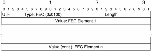
As shown in Figure 3-6, contents of the fields in the FEC TLV are as follows:
- U and F The Unknown (U) and the Forward unknown (F) bits are both set to 0.
- Type This is set to a value of 0x0100, indicating that this is an FEC TLV.
- Length Indicates the length of the Value field (the FEC elements) in octets.
- Value In the case of an FEC TLV, the Value field contains one or more FEC elements. In the case of LDP Label Mapping messages used with AToM, however, only one FEC element is included in an FEC TLV (the specific type of FEC element is discussed later in this section).
Note
Note that the format of the FEC TLV (U and F bits; Type, Length, and Value fields) is common to all LDP TLVs.
Figure 3-7 illustrates the Generic Label TLV.
Figure 3-7. Generic Label TLV
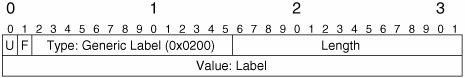
The Generic Label TLV can be described as follows:
- U and F bits Both of these must be set to 0.
- Type This field contains the value 0x0200, which indicates that this is a Generic Label FEC.
- Length This indicates the length of the Value field.
- Value This field contains a label. In the case of a pseudowire Label Mapping message, this field contains a PW (VC) label.
So far so goodan LDP Label Mapping message includes FEC and Generic Label TLVs. But what about the FEC element that is included in the FEC TLV (see Figure 3-6)? As previously mentioned, only one FEC element (called a pseudowire [PW] ID FEC element) is included when an LDP Label Mapping message is used with AToM, as illustrated in Figure 3-8.
Figure 3-8. PW (VC) ID FEC Element
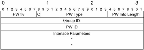
The PW ID FEC element consists of the following fields:
- PW (VC) TLV This field contains the value of 128, indicating that this is a PW ID FEC element.
- C bit This bit indicates whether a control word will be used with this pseudowire (will be included in pseudowire data channel packets [see Figure 3-2]). If the C bit is set to 1, a control word will be used; if the C bit is set to 0, a control word will not be used.
- PW (VC) Type This indicates the pseudowire type as listed Table 3-2.
Table 3-2. MPLS Pseudowire Types
Pseudowire (PW/VC) Type
Description
0x0001
Frame Relay DLCI (Martini mode)
0x0002
ATM AAL5 SDU VCC transport
0x0003
ATM transparent cell transport
0x0004
Ethernet Tagged mode
0x0005
Ethernet
0x0006
High-Level Data Link Control (HDLC)
0x0007
PPP
0x0008
Synchronous Optical Network (SONET)/Synchronous Digital Hierarchy (SDH) Circuit Emulation Service over MPLS (CEM)
0x0009
ATM n-to-1 VCC cell transport
0x000A
ATM n-to-1 VPC cell transport
0x000B
IP Layer 2 Transport
0x000C
ATM 1-to-1 VCC Cell mode
0x000D
ATM 1-to-1 VPC Cell mode
0x000E
ATM AAL5 PDU VCC transport
0x000F
Frame Relay port mode
0x0010
SONET/SDH Circuit Emulation over Packet (CEP)
0x0011
Structure-agnostic E1 over Packet (SAToP)
0x0012
Structure-agnostic T1 (DS1) over Packet (SAToP)
0x0013
Structure-agnostic E3 over Packet (SAToP)
0x0014
Structure-agnostic T3 (DS3) over Packet (SAToP)
0x0015
CESoPSN basic mode
0x0016
TDMoIP AAL1 mode
0x0017
CESoPSN TDM with CAS
0x0018
TDMoIP AAL2 mode
0x0019
Frame Relay DLCI
- PW (VC) Info Length This field specifies the length of the PW ID and Interface Parameters fields (in octets).
- Group ID The Group ID field contains a value that is used to represent a group of pseudowires.
The Group ID can be used to group a number of pseudowires on an interface or virtual tunnel and can, for example, be useful when a PE router needs to withdraw labels for a number of pseudowires associated with a particular interface, or send a notification message that applies to a number of pseudowires associated with a particular interface.
- PW (VC) ID This, together with the PW type, uniquely identifies an AToM pseudowire.
- Interface Parameters This field is used to signal attachment circuit interface parameters such as maximum transmission unit (MTU) and interface description string.
Figure 3-9 shows the format of the Interface Parameters field contained in the PW ID FEC element (also see Figure 3-8).
Figure 3-9. Interface Parameters Field
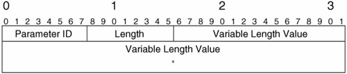
The components of the Interface Parameters field can be described as follows:
- Parameter ID Identifies the type of interface parameter (interface MTU, description, and so on) contained in the Variable Length Value field.
- Length Specifies the overall length of the Interface Parameters field, including Parameter ID and Length.
- Variable Length Value Contains the actual data, whether the interface MTU, the interface description, or other interface parameter.
If you are a little confused about how all of these TLVs, FEC elements, and Interface Parameters fields fit together, take a look at Figure 3-10.
Figure 3-10. Interrelationship Between FEC/Generic Label TLVs, PW ID FEC Element, and Interface Parameters Field
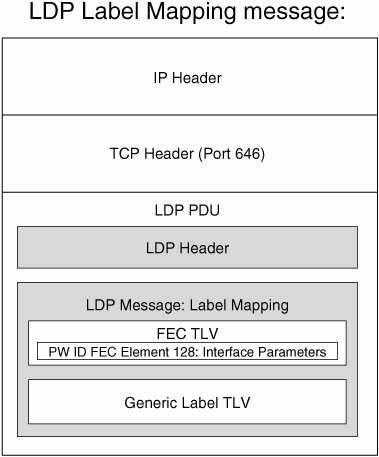
As shown in Figure 3-10, the LDP PDU consists of the following:
- An LDP header.
- An LDP message, which in this case is a Label Mapping message. The LDP Label Mapping message comprises the following:
- An FEC TLV
- A Generic Label TLV
Although not shown in Figure 3-10, the Label Mapping message may also contain zero or more optional parameter TLVs.
Finally, the FEC TLV contains a PW ID FEC element in its Interface Parameters field.
Example 3-3 shows the exchange of PW (VC) labels between peer Cisco PE routers.
Example 3-3. Exchange of PW (VC) Labels Between Peer PE Routers
San.Jose.PE#debug mpls l2transport signaling message AToM LDP message debugging is on San.Jose.PE# *May 26 20:34:21.555: %LDP-5-NBRCHG: LDP Neighbor 10.1.1.1:0 is UP (line 1) *May 26 20:34:21.555: AToM LDP [10.1.1.1]: Sending label mapping msg (line 2) vc type 6, cbit 1, vc id 1001, group id 0, vc label 21, status 0, mtu 1500 (line 3) *May 26 20:34:21.835: AToM LDP [10.1.1.1]: Received label mapping msg, id 99 (line 4) vc type 6, cbit 1, vc id 1001, group id 3, vc label 21, status 0, mtu 1500 (line 5) San.Jose.PE# |
As you can see in Example 3-3, the LDP session has been established (highlighted line 1), and label bindings have been sent and received (highlighted lines 2 and 3).
A closer look at highlighted lines 2 and 3 shows some of the information contained in the PW (VC) ID FEC element (see Figure 3-8), such as the following:
- The VC (PW) type (6, see Table 3-2)
- The C bit setting
- The VC (PW) ID (1001)
- The Group ID (0)
- The VC (PW) label (21), status (0), and (attachment circuit) interface MTU (1500 bytes)
You can also view AToM label bindings using the show mpls l2transport binding command.
Note
The debug mpls l2transport signaling message command is used here for illustrative purposes only. Exercise caution when using debug commands because they can disrupt the operation of heavily loaded routers.
So that is pseudowire setupnow on to pseudowire status signaling.
AToM Status Signaling
LDP is not only used to setup pseudowires, it can also be used to signal pseudowire status. This can be important if, for example, one PE router wants to signal its peer PE router that its attachment circuit has changed state.
If a PE router wants to signal attachment circuit status changes to its peer PE router, it can use two different methods:
- It can send an LDP Label Withdraw message.
- It can send an LDP Notification message.
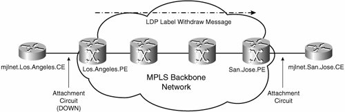
Signaling Attachment Circuit Status Changes with an LDP Label Withdraw Message
The LDP Label Withdraw message can be used to signal circuit down status.
Figure 3-11 shows the signaling of circuit down status using the LDP Label Withdraw message.
Figure 3-11. Signaling Circuit Down Status Using the LDP Withdraw Message
Example 3-4 shows the LDP Label Withdraw message being used to signal attachment circuit status between peer Cisco PE routers.
Example 3-4. LDP Label Withdraw Message Being Used to Signal Pseudowire Status Between Peer Cisco PE Routers
San.Jose.PE#debug mpls l2transport signaling message AToM LDP message debugging is on San.Jose.PE# *May 26 21:48:54.279: AToM LDP [10.1.1.1]: Received label withdraw msg, id 279 (line 1) vc type 6, cbit 1, vc id 1001, group id 3, vc label 21, status 0, mtu 0 (line 2) San.Jose.PE# |
Highlighted line 1 shows that the local PE router has received an LDP Label Withdraw message from the remote PE router indicating an attachment circuit status change.
Signaling Attachment Circuit Status Changes with an LDP Notification Message
This alternative (and relatively recent) method of signaling status must be negotiated when LDP Label Mapping messages are exchanged during pseudowire setup (see Figure 3-5).
If the PE router initiating pseudowire setup supports status signaling using the LDP Notification message, it includes a PW Status TLV along with the FEC and Generic Label TLVs in the LDP Label Mapping message.
If the peer PE router also supports status signaling using the LDP Notification message, it also includes a PW Status TLV in the LDP Label Mapping message that it sends. If, on the other hand, either peer PE router does not include the PW Status TLV in the LDP Label Mapping message that it sends, both peer PE routers revert to using LDP Label Withdraw messages to signal status.
Figure 3-12 shows the format of the LDP Notification message used to signal pseudowire status.
Figure 3-12. Format of the LDP Notification Message Used to Signal Status
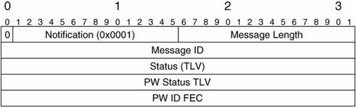
The key fields to notice in the LDP Notification message are the Status and PW Status TLVs, as well as the PW ID FEC element (see also Figure 3-8). Note that the PW ID FEC element does not include the Interface Parameters field when carried in the LDP Notification message.
A status code that indicates the status of the pseudowire is carried in the PW Status TLV. The PW ID FEC element is carried in the LDP Notification message to indicate the ID of the pseudowire (PW ID) or group (Group ID) to which the status code corresponds.
Table 3-3 shows possible PW status codes that can be carried in the PW Status TLV in the LDP Notification message.
|
(PW) Status Code |
Description |
|---|---|
|
0x00000000 |
Pseudowire forwarding (clear all failures) |
|
0x00000001 |
Pseudowire not forwarding |
|
0x00000002 |
Local attachment circuit (ingress) receive fault |
|
0x00000004 |
Local attachment circuit (egress)transmit fault |
|
0x00000008 |
Local PSN-facing PW (ingress) receive fault |
|
0x00000010 |
Local PSN-facing PW (egress) transmit fault |
As you can see in Table 3-3, the PW Status TLV can be used to signal a number of statuses. So, signaling pseudowire status using the LDP Notification message (including a PW Status TLV) is more flexible than signaling pseudowire status using the LDP Label Withdraw message because the LDP Label Withdraw message can only be used to signal attachment circuit down status.
Figure 3-13 illustrates negotiation of pseudowire status signaling (with the LDP Notification message) during LDP Label Mapping message exchange.
Figure 3-13. Negotiation of Pseudowire Status Signaling (with the LDP Notification Message) During LDP Label Mapping Message Exchange
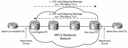
In Figure 3-13, both peer PE routers include the PW Status TLV in the LDP Label Mapping messages that they send, and this results in the PE routers using the LDP Notification message to signal pseudowire status.
Figure 3-14 shows the signaling of pseudowire status using the LDP Notification message.
Figure 3-14. Signaling Pseudowire Status Using the LDP Notification Message

AToM Data Channel Packet Forwarding
The overall format of AToM data channel packets is shown in Figure 3-2 on page 139. As you can see, the packet format consists of the following:
- One or more tunnel labels These tunnel labels can be advertised between adjacent PE and P routers (LSRs) using LDP, TDP, or RSVP-TE. Note, however, that the use of the Cisco-proprietary Tag Distribution Protocol (TDP) is now deprecated in MPLS networks.
- A PW label This is also referred to as the VC label and serves as a demultiplexor that ensures that data channel packets are correctly associated with an attachment circuit.
The PW label serves the same purpose as the session header (session ID and optional cookie) does with L2TPv3 pseudowires.
- An optional control word This performs the same function as the service-specific sublayer with L2TPv3 pseudowires.
The PW label and the presence (or otherwise) of a control word are advertised in LDP Label Mapping messages exchanged during pseudowire setup.
Figure 3-15 depicts the transmission of AToM data channel packets.
Figure 3-15. Transmission of AToM Data Channel Packets
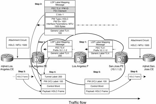
Figure 3-15 shows the transport of a AToM data channel packet across the MPLS backbone network between Los.Angeles.PE to San.Jose.PE (see the lower half of the figure), but it also shows how control channel packets (see the upper half of the figure) influence the form of data channel packets.
If you take a close look at Figure 3-15, you can see that the following events occur:
|
Step 1. |
San.Jose.PE advertises a (tunnel) label (3 [implicit-null]) corresponding to its IP address (10.1.1.2) to Los.Angeles.P using LDP. |
|
Step 2. |
San.Jose.PE sends an LDP Label Mapping message to Los.Angeles.PE. This message includes an FEC TLV (Figure 3-6) and a Generic Label TLV (Figure 3-7). |
|
Step 3. |
Los.Angeles.PE now receives an HDLC frame on the attachment circuit connected to mjlnet.Los.Angeles.CE. |
|
Step 4. |
Los.Angeles.PE encapsulates the HDLC with a control word (this is included because the C bit was set to 1 in the PW ID FEC element in the LDP Label Mapping message in Step 2), a PW (VC) label (100, which was included in the Generic Label FEC in the LDP Label Mapping message sent in Step 2), and a tunnel label (200, which was received from Los.Angeles.P in Step 1). The purpose of the tunnel label is to transport the encapsulated frame to the egress PE router, which in this case is San.Jose.PE. |
|
Step 5. |
Los.Angeles.P pops the tunnel label because the outgoing label (3, implicit-null) indicates that the egress PE router is the next hop (so, Los.Angeles.P performs a penultimate hop pop [PHP]). |
|
Step 6. |
San.Jose.PE receives the encapsulated HDLC frame, and removes the PW (VC) label and the control word. The PW (VC) label indicates the local attachment circuit on which the encapsulated HDLC frame should be forwarded, and so San.Jose.PE then sends the HDLC frame to mjlnet.San.Jose.CE. |
That is AToM data channel packet forwarding from Los.Angeles.PE to San.Jose.PE. Data channel packet forwarding from San.Jose.PE to Los.Angeles.PE happens in exactly the same manner, just in the opposite direction.
Now that you understand the background to AToM pseudowire operation, it is time to move on to AToM configuration.
Part I: Understanding VPN Technology
What Is a Virtual Private Network?
- What Is a Virtual Private Network?
- VPN Devices
- Deploying Site-to-Site and Remote Access VPNs: A Comparison
- Summary
- Review Questions
Part II: Site-to-Site VPNs
Designing and Deploying L2TPv3-Based Layer 2 VPNs
- Designing and Deploying L2TPv3-Based Layer 2 VPNs
- Benefits and Drawbacks of L2TPv3-Based L2VPNs
- L2TPv3 Pseudowire Operation
- Configuring and Verifying L2TPv3 Pseudowires
- Summary
- Review Questions
Designing and Implementing AToM-Based Layer 2 VPNs
- Designing and Implementing AToM-Based Layer 2 VPNs
- Benefits and Drawbacks of AToM-Based L2VPNs
- AToM Pseudowire Operation
- Deploying AToM Pseudowires
- Implementing Advanced AToM Features
- Summary
- Review Questions
Designing MPLS Layer 3 Site-to-Site VPNs
- Designing MPLS Layer 3 Site-to-Site VPNs
- Advantages and Disadvantages of MPLS Layer 3 VPNs
- MPLS Layer 3 VPNs Overview
- A Detailed Examination of MPLS Layer 3 VPNs
- Deploying MPLS Layer 3 VPNs
- Summary
- Review Questions
Advanced MPLS Layer 3 VPN Deployment Considerations
- Advanced MPLS Layer 3 VPN Deployment Considerations
- The Carriers Carrier Architecture
- The Inter-Autonomous System/Interprovider MPLS VPN Architecture
- Supporting Multicast Transport in MPLS Layer 3 VPNs
- Implementing QoS for MPLS Layer 3 VPNs
- Supporting IPv6 Traffic Transport in MPLS Layer 3 VPNs Using 6VPE
- Summary
- Review Questions
Deploying Site-to-Site IPsec VPNs
- Deploying Site-to-Site IPsec VPNs
- Advantages and Disadvantages of IPsec Site-to-Site VPNs
- IPsec: A Security Architecture for IP
- Deploying IPsec VPNs: Fundamental Considerations
- Summary
- Review Questions
Scaling and Optimizing IPsec VPNs
- Scaling and Optimizing IPsec VPNs
- Scaling IPsec Virtual Private Networks
- Ensuring High Availability in an IPsec VPN
- Designing QoS for IPsec VPNs
- MTU and Fragmentation Considerations in an IPsec VPN
- Summary
- Review Questions
Part III: Remote Access VPNs
Designing and Implementing L2TPv2 and L2TPv3 Remote Access VPNs
- Designing and Implementing L2TPv2 and L2TPv3 Remote Access VPNs
- Benefits and Drawbacks of L2TP Remote Access VPNs
- Operation of L2TP Voluntary/Client-Initiated Tunnel Mode
- Implementing L2TP Voluntary/Client-Initiated Tunnel Mode Remote Access VPNs
- Designing and Implementing L2TP Compulsory/NAS-Initiated Tunnel Mode Remote Access VPNs
- Integrating L2TP Remote Access VPNs with MPLS VPNs
- Summary
- Review Questions
Designing and Deploying IPsec Remote Access and Teleworker VPNs
- Designing and Deploying IPsec Remote Access and Teleworker VPNs
- Comparing IPsec Remote Access VPNs with Other Types of Remote Access VPNs
- Understanding IKE in an IPsec Remote Access VPN Environment
- Deploying IPsec Remote Access VPNs Using Preshared Key and Digital Signature Authentication
- Summary
- Review Questions
Designing and Building SSL Remote Access VPNs (WebVPN)
- Designing and Building SSL Remote Access VPNs (WebVPN)
- Comparing SSL VPNs to Other Types of Remote Access VPNs
- Understanding the Operation of SSL Remote Access VPNs
- Using Clientless SSL Remote Access VPNs (WebVPN) on the Cisco VPN 3000 Concentrator
- Implementing Full Network Access Using the Cisco SSL VPN Client
- Strengthening SSL Remote Access VPNs Security by Implementing Cisco Secure Desktop
- Enabling SSL VPNs (WebVPN) on Cisco IOS Devices
- Deploying SSL VPNs (WebVPN) on the ASA 5500
- Summary
- Review Questions
Part IV: Appendixes
Designing and Building SSL Remote Access VPNs (WebVPN)
- Designing and Building SSL Remote Access VPNs (WebVPN)
- Appendix A. VPLS and IPLS Layer 2 VPNs
- Understanding VPLS
- Understanding IPLS
- Summary: Comparing VPLS and IPLS
Appendix B. Answers to Review Questions
EAN: 2147483647
Pages: 124
