Understanding IPLS
VPLS is particularly applicable where multiprotocol multipoint Ethernet transport is required. If only multipoint IP connectivity is required between CE routers (rather than CE switches), IPLS might be an attractive option. IPLS provides IP-only emulated LAN connectivity across a MAN or WAN.
VPLS requires that PE devices have a MAC address learning capability, along with the associated mechanisms such as aging. Unfortunately, it might be difficult to add these capabilities in the data plane (the traffic-forwarding path) to some types of PE devices. In these circumstances, IPLS may be a good solution because instead of using the type of MAC address learning mechanisms inherent in Ethernet switches, in IPLS, MAC (and IP) address learning is accomplished via signaling between PE devices (in the control plane).
As the name suggests, an IPLS can only be used to transport IP and Address Resolution Protocol (ARP) traffic. Non-IP traffic received by PE devices on attachment circuits is dropped.
Unicast and Broadcast/Multicast Pseudowires in IPLS
Traffic forwarding is also different in IPLS when compared to VPLS. In each IPLS instance (a separate emulated LAN), a unidirectional pseudowire is set up for unicast traffic from each remote peer IPLS PE device to the local PE device for each locally attached CE device. Figure A-6 illustrates this concept.
Figure A-6. Unidirectional Unicast Pseudowires in IPLS
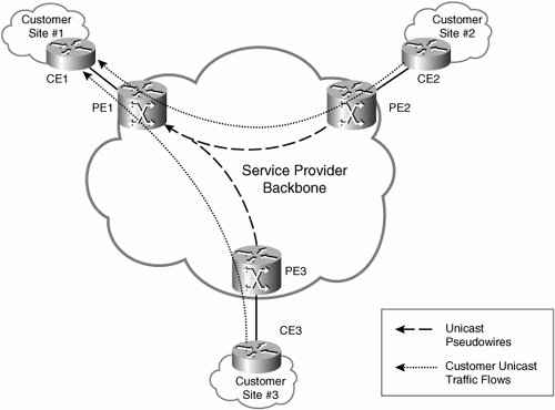
As shown in Figure A-6, there are three PE devices: PE1, PE2, and PE3. There are also three attached CE devices: CE1, CE2, and CE3. There is one IPLS instance in this example (one IP-only emulated LAN).
Unidirectional pseudowires are set up from PE2 and PE3 to PE1 to forward unicast traffic from CE devices directly attached to PE2 (CE2) and PE3 (CE3) to CE1.
Similarly, unidirectional pseudowires are set up from PE1 and PE3 to PE2 (not shown) to forward traffic from CE devices attached to those PE devices (CE1 and CE3) to CE2.
Unidirectional pseudowires are also established from PE1 and PE2 to PE3 to forward unicast traffic from CE devices attached to PE1 and PE2 to CE3.
The pseudowire type used for unicast pseudowires in IPLS is IP Layer 2 Transport (see Table 3-2 in Chapter 3).
Multicast and broadcast traffic is handled separately from unicast traffic in an IPLS instance. Separate broadcast/multicast pseudowires are set up from each PE device to every other PE device in an IPLS instance. These broadcast/multicast pseudowires are also unidirectional in nature and are used to forward IP broadcast and multicast traffic as well as ARP packets.
Figure A-7 illustrates the pseudowires used to forward broadcast/multicast traffic from CE2 and CE3 to CE1.
Figure A-7. Broadcast/Multicast Pseudowires in IPLS
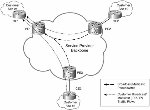
Although not shown in Figure A-7, separate unidirectional pseudowires are required to transport broadcast/multicast traffic from PE1 and PE3 to PE2 (per IPLS instance). Separate unidirectional pseudowires are also needed to transport broadcast/multicast traffic from PE1 and PE2 to PE3 (per IPLS instance).
The pseudowire type used for broadcast/multicast pseudowires in IPLS is Ethernet (see Table 3-2).
Both unicast and broadcast/multicast pseudowires are established and maintained using LDP. In fact, the setup and maintenance procedures are similar to that described in Chapter 3.
When setting up pseudowires for unicast traffic, a PE device can assign the same pseudowire (VC) label to each pseudowire that transports traffic to the same locally attached CE device, which in effect creates a multipoint-to-point pseudowire.
A PE device can also assign the same pseudowire (VC) label to each broadcast/multicast pseudowire in an IPLS instance. This again creates a multipoint-to-point pseudowire.
In summary, although there is a multipoint-to-point pseudowire for unicast traffic per CE device in an IPLS instance, there is only one multipoint-to-point broadcast/multicast pseudowire per PE device in an IPLS instance.
It is worth noting that the broadcast/multicast pseudowire for an IPLS instance is the principle pseudowire for the bundle of pseudowires, including the unicast pseudowires for the IPLS instance. If the broadcast/multicast pseudowire goes down, the unicast pseudowires associated with the same IPLS instance must be torn down.
As previously described, IPLS PE devices do not use the regular MAC address learning procedures described in IEEE 802.1D. Instead, PE advertises the IP and MAC addresses of locally connected CE devices to other PE devices during pseudowire setup.
Unicast and Broadcast/Multicast Forwarding in IPLS
When an IPLS PE device receives a unicast frame on an attachment circuit, the PE device does a lookup. If a match is found, the packet is either forwarded to another local attachment circuit or, minus its Ethernet header, over a pseudowire to a peer PE device as appropriate.
When a unicast packet is received over a pseudowire, the receiving PE device prepends a MAC header and forwards the packet to the appropriate local attachment circuit. The source and destination MAC addresses included in the header are the local PE device's MAC address and locally connected CE device's MAC address, respectively.
When a PE device receives an IP Ethernet broadcast/multicast on an attachment circuit, it replicates that broadcast/multicast on each of the broadcast/multicast pseudowires associated with the IPLS instance in question. A PE device that receives an IP broadcast/multicast over a pseudowire replicates this broadcast/multicast to each of the local attachment circuits that corresponds to the IPLS instance.
Note
It is worth noting that although transport of customer traffic between PE devices is assumed to be via MPLS pseudowires in this appendix, it is also possible to use tunneling protocols such as Layer Two Tunneling Protocol version 3 (L2TPv3) or Generic Routing Encapsulation (GRE) to provide transport in IPLS.
Like a VPLS instance, each IPLS instance is a separate broadcast domain. CE devices in an IPLS instance appear to be directly connected to each other.
PE devices discover the IP and MAC addresses of connected CE devices by snooping their transmissions of IP and ARP packets on the attachment circuits. After a CE device has been discovered on an attachment circuit, a PE device monitors its continued presence by periodically sending ARP requests. If the CE device fails to respond to a certain number of these requests, the PE device interprets this as a loss of connectivity with that CE device.
Part I: Understanding VPN Technology
What Is a Virtual Private Network?
- What Is a Virtual Private Network?
- VPN Devices
- Deploying Site-to-Site and Remote Access VPNs: A Comparison
- Summary
- Review Questions
Part II: Site-to-Site VPNs
Designing and Deploying L2TPv3-Based Layer 2 VPNs
- Designing and Deploying L2TPv3-Based Layer 2 VPNs
- Benefits and Drawbacks of L2TPv3-Based L2VPNs
- L2TPv3 Pseudowire Operation
- Configuring and Verifying L2TPv3 Pseudowires
- Summary
- Review Questions
Designing and Implementing AToM-Based Layer 2 VPNs
- Designing and Implementing AToM-Based Layer 2 VPNs
- Benefits and Drawbacks of AToM-Based L2VPNs
- AToM Pseudowire Operation
- Deploying AToM Pseudowires
- Implementing Advanced AToM Features
- Summary
- Review Questions
Designing MPLS Layer 3 Site-to-Site VPNs
- Designing MPLS Layer 3 Site-to-Site VPNs
- Advantages and Disadvantages of MPLS Layer 3 VPNs
- MPLS Layer 3 VPNs Overview
- A Detailed Examination of MPLS Layer 3 VPNs
- Deploying MPLS Layer 3 VPNs
- Summary
- Review Questions
Advanced MPLS Layer 3 VPN Deployment Considerations
- Advanced MPLS Layer 3 VPN Deployment Considerations
- The Carriers Carrier Architecture
- The Inter-Autonomous System/Interprovider MPLS VPN Architecture
- Supporting Multicast Transport in MPLS Layer 3 VPNs
- Implementing QoS for MPLS Layer 3 VPNs
- Supporting IPv6 Traffic Transport in MPLS Layer 3 VPNs Using 6VPE
- Summary
- Review Questions
Deploying Site-to-Site IPsec VPNs
- Deploying Site-to-Site IPsec VPNs
- Advantages and Disadvantages of IPsec Site-to-Site VPNs
- IPsec: A Security Architecture for IP
- Deploying IPsec VPNs: Fundamental Considerations
- Summary
- Review Questions
Scaling and Optimizing IPsec VPNs
- Scaling and Optimizing IPsec VPNs
- Scaling IPsec Virtual Private Networks
- Ensuring High Availability in an IPsec VPN
- Designing QoS for IPsec VPNs
- MTU and Fragmentation Considerations in an IPsec VPN
- Summary
- Review Questions
Part III: Remote Access VPNs
Designing and Implementing L2TPv2 and L2TPv3 Remote Access VPNs
- Designing and Implementing L2TPv2 and L2TPv3 Remote Access VPNs
- Benefits and Drawbacks of L2TP Remote Access VPNs
- Operation of L2TP Voluntary/Client-Initiated Tunnel Mode
- Implementing L2TP Voluntary/Client-Initiated Tunnel Mode Remote Access VPNs
- Designing and Implementing L2TP Compulsory/NAS-Initiated Tunnel Mode Remote Access VPNs
- Integrating L2TP Remote Access VPNs with MPLS VPNs
- Summary
- Review Questions
Designing and Deploying IPsec Remote Access and Teleworker VPNs
- Designing and Deploying IPsec Remote Access and Teleworker VPNs
- Comparing IPsec Remote Access VPNs with Other Types of Remote Access VPNs
- Understanding IKE in an IPsec Remote Access VPN Environment
- Deploying IPsec Remote Access VPNs Using Preshared Key and Digital Signature Authentication
- Summary
- Review Questions
Designing and Building SSL Remote Access VPNs (WebVPN)
- Designing and Building SSL Remote Access VPNs (WebVPN)
- Comparing SSL VPNs to Other Types of Remote Access VPNs
- Understanding the Operation of SSL Remote Access VPNs
- Using Clientless SSL Remote Access VPNs (WebVPN) on the Cisco VPN 3000 Concentrator
- Implementing Full Network Access Using the Cisco SSL VPN Client
- Strengthening SSL Remote Access VPNs Security by Implementing Cisco Secure Desktop
- Enabling SSL VPNs (WebVPN) on Cisco IOS Devices
- Deploying SSL VPNs (WebVPN) on the ASA 5500
- Summary
- Review Questions
Part IV: Appendixes
Designing and Building SSL Remote Access VPNs (WebVPN)
- Designing and Building SSL Remote Access VPNs (WebVPN)
- Appendix A. VPLS and IPLS Layer 2 VPNs
- Understanding VPLS
- Understanding IPLS
- Summary: Comparing VPLS and IPLS
Appendix B. Answers to Review Questions
EAN: 2147483647
Pages: 124
